EP0538973A1 - Ensemble compresseur avec refroidissement par air - Google Patents
Ensemble compresseur avec refroidissement par air Download PDFInfo
- Publication number
- EP0538973A1 EP0538973A1 EP92250305A EP92250305A EP0538973A1 EP 0538973 A1 EP0538973 A1 EP 0538973A1 EP 92250305 A EP92250305 A EP 92250305A EP 92250305 A EP92250305 A EP 92250305A EP 0538973 A1 EP0538973 A1 EP 0538973A1
- Authority
- EP
- European Patent Office
- Prior art keywords
- oil
- air
- flange
- separator
- compressor
- Prior art date
- Legal status (The legal status is an assumption and is not a legal conclusion. Google has not performed a legal analysis and makes no representation as to the accuracy of the status listed.)
- Granted
Links
- 230000006835 compression Effects 0.000 abstract description 4
- 238000007906 compression Methods 0.000 abstract description 4
- 238000010276 construction Methods 0.000 abstract description 4
- 238000005192 partition Methods 0.000 abstract description 2
- 238000007789 sealing Methods 0.000 abstract description 2
- 238000002347 injection Methods 0.000 description 11
- 239000007924 injection Substances 0.000 description 11
- 239000000203 mixture Substances 0.000 description 8
- 238000001816 cooling Methods 0.000 description 7
- 238000005461 lubrication Methods 0.000 description 5
- 230000008878 coupling Effects 0.000 description 2
- 238000010168 coupling process Methods 0.000 description 2
- 238000005859 coupling reaction Methods 0.000 description 2
- 238000010586 diagram Methods 0.000 description 2
- 238000000926 separation method Methods 0.000 description 2
- 239000008186 active pharmaceutical agent Substances 0.000 description 1
- 230000001914 calming effect Effects 0.000 description 1
- 238000011161 development Methods 0.000 description 1
- 230000018109 developmental process Effects 0.000 description 1
- 238000002474 experimental method Methods 0.000 description 1
- 239000000945 filler Substances 0.000 description 1
- 238000001914 filtration Methods 0.000 description 1
- 230000005484 gravity Effects 0.000 description 1
- 238000000034 method Methods 0.000 description 1
- 230000000630 rising effect Effects 0.000 description 1
- 238000010408 sweeping Methods 0.000 description 1
Images


Classifications
-
- F—MECHANICAL ENGINEERING; LIGHTING; HEATING; WEAPONS; BLASTING
- F04—POSITIVE - DISPLACEMENT MACHINES FOR LIQUIDS; PUMPS FOR LIQUIDS OR ELASTIC FLUIDS
- F04C—ROTARY-PISTON, OR OSCILLATING-PISTON, POSITIVE-DISPLACEMENT MACHINES FOR LIQUIDS; ROTARY-PISTON, OR OSCILLATING-PISTON, POSITIVE-DISPLACEMENT PUMPS
- F04C29/00—Component parts, details or accessories of pumps or pumping installations, not provided for in groups F04C18/00 - F04C28/00
- F04C29/02—Lubrication; Lubricant separation
- F04C29/026—Lubricant separation
-
- F—MECHANICAL ENGINEERING; LIGHTING; HEATING; WEAPONS; BLASTING
- F04—POSITIVE - DISPLACEMENT MACHINES FOR LIQUIDS; PUMPS FOR LIQUIDS OR ELASTIC FLUIDS
- F04C—ROTARY-PISTON, OR OSCILLATING-PISTON, POSITIVE-DISPLACEMENT MACHINES FOR LIQUIDS; ROTARY-PISTON, OR OSCILLATING-PISTON, POSITIVE-DISPLACEMENT PUMPS
- F04C23/00—Combinations of two or more pumps, each being of rotary-piston or oscillating-piston type, specially adapted for elastic fluids; Pumping installations specially adapted for elastic fluids; Multi-stage pumps specially adapted for elastic fluids
-
- F—MECHANICAL ENGINEERING; LIGHTING; HEATING; WEAPONS; BLASTING
- F04—POSITIVE - DISPLACEMENT MACHINES FOR LIQUIDS; PUMPS FOR LIQUIDS OR ELASTIC FLUIDS
- F04C—ROTARY-PISTON, OR OSCILLATING-PISTON, POSITIVE-DISPLACEMENT MACHINES FOR LIQUIDS; ROTARY-PISTON, OR OSCILLATING-PISTON, POSITIVE-DISPLACEMENT PUMPS
- F04C29/00—Component parts, details or accessories of pumps or pumping installations, not provided for in groups F04C18/00 - F04C28/00
- F04C29/0007—Injection of a fluid in the working chamber for sealing, cooling and lubricating
-
- F—MECHANICAL ENGINEERING; LIGHTING; HEATING; WEAPONS; BLASTING
- F04—POSITIVE - DISPLACEMENT MACHINES FOR LIQUIDS; PUMPS FOR LIQUIDS OR ELASTIC FLUIDS
- F04C—ROTARY-PISTON, OR OSCILLATING-PISTON, POSITIVE-DISPLACEMENT MACHINES FOR LIQUIDS; ROTARY-PISTON, OR OSCILLATING-PISTON, POSITIVE-DISPLACEMENT PUMPS
- F04C29/00—Component parts, details or accessories of pumps or pumping installations, not provided for in groups F04C18/00 - F04C28/00
- F04C29/0092—Removing solid or liquid contaminants from the gas under pumping, e.g. by filtering or deposition; Purging; Scrubbing; Cleaning
Definitions
- the invention relates to an air-cooled compressor system according to the preamble of claim 1.
- a generic air-cooled compressor system can be found in EP-PS 0 206 153. It has an oil separator tank, on the outside of which a screw compressor is flanged as a separate part, and openings are provided in the flange area for the intake of air and for the discharge of the compressed air into the oil separator tank.
- the housing of the oil separator tank which is open at the top, is sealed with a lid.
- the cover is designed so that it acts as a cyclone separator in the sense of an oil pre-separation.
- the pre-de-oiled air then flows radially from the outside inwards through an oil separator, which is arranged in the upper part of the oil separator tank as a replaceable insert.
- the separated oil collects in the lower part of the oil separator tank, from where it is fed to the injection point of the screw compressor after cooling and filtering.
- the oil is cooled via an oil cooler, which is cooled by a fan together with the drive motor.
- the proposed compressor system is not suitable for a system operating in the low pressure range, since the number of parts required is too large and the overall construction is too complex.
- a compressor system especially for generating compressed air in the low pressure range has already been described in detail (see brochure Demag-Wittig 1976 series DS). This is a compact system in which the oil required for lubrication is fed to the multi-cell compressor stage by means of a pump driven by the rotor shaft.
- this type of oil lubrication is called fresh oil lubrication, in which a very small amount of oil in the range of a few milligrams per revolution is fed to the compressor stage.
- This oil supply only has the task of keeping the sliding friction generated when the rotor slides are placed against the housing wall and in the rotor slots.
- the temperature rise of the emerging air-oil mixture resulting from the adiabatic compression remains unaffected by this, which in a single-stage compressor system with a final pressure of about 3 bar is in the range of 180 degrees Celsius. Since, depending on the intended use of the compressor system, this high outlet temperature is not desired, it is known to cool the air / oil mixture ejected from the pressure port before delivery to the point of use.
- a fan wheel is arranged on the shaft end of the rotor shaft facing the drive, which blows air with a cooling block arranged around this fan wheel.
- the oil-containing compressed air flows in the tubes of the cooling block and is cooled accordingly in this way. After cooling, the oil in the compressed air is discharged through deflection channels and separator packs arranged in the machine base plate and used in the Reservoir returned.
- the object of the invention is to provide an air-cooled compressor system for generating compressed air in the low pressure range between 1 and 4 bar, which while maintaining the compact design has a high degree of efficiency and the compression closer to the isotherms and with a low residual oil content with a maximum final air temperature of 100 Degrees Celsius can be produced inexpensively with fewer components.
- oil is injected into the multi-cell compressor stage in larger quantities, ie 10 - 20 g per cubic meter of intake air.
- This improves hydrodynamic lubrication and increases volumetric efficiency.
- the oil supply takes place in a known manner via the system pressure, so that the otherwise customary oil pump can be dispensed with.
- it is necessary to determine the degree of pre-de-oiling so that the downstream fine separator is not overused.
- a suction and a pressure chamber are separated by an intermediate wall, the latter being designed as a pre-separator and forming the oil sump in the lower region. It is essential that the opening in the pressure chamber for the discharge of the compressed air is arranged so that the oil-containing air, as guided in a duct, first strikes a wall perpendicular to the direction of flow and then the direction of flow is greatly slowed down by the passage of the oil-containing Air into the pressure chamber with a large cross-sectional area.
- the oil droplets Due to the calming of the air flow, the oil droplets have enough time to separate from the mixture so that only small amounts of oil are entrained in the downstream oil separator, where the remaining oil, with the exception of a residual oil content of less than 5 ppm, preferably less than 3 ppm, is separated out via appropriate filter elements becomes.
- the oil collecting in the oil sump of the oil separating tank is pressed by means of the system pressure via a line into the oil cooler, which is air-cooled by a fan, and from there via an injection line into the multi-cell compressor stage.
- the injection into the compressor takes place via at least one injection hole, which is arranged in the direction of rotation with respect to the cell pressure in such a way that a sufficient system overpressure between the pressure port and the injection point is maintained for the delivery of the oil, taking into account the pressure losses. It has proven to be particularly advantageous if two injection bores are provided for the injection, which are preferably arranged in the respective cover area of the compressor. Experiments have shown that the achievable volumetric efficiency is highest with such an arrangement. The amount of oil injected is only about that appropriate line and bore cross-sections controlled, without a complex regulation is required.
- the oil separator tank is designed as a gravity separator, which means that the air-oil mixture rises from the lower area of the pressure chamber upwards.
- the fine oil separator and the air intake filter are attached to the flange-like surface of the oil separator tank that is parallel to the housing feet. These are connected to the pressure or the suction chamber via openings in the flange-like surface.
- the fine oil separator is sealed by a hood attached to the flange-like surface.
- the pre-oiled mixture flows from the pressure chamber of the oil separator tank through the opening in the flange-like surface into the oil separator and penetrates the filter elements radially from the inside to the outside.
- the oil draining from the filter elements is collected in an annular groove which is arranged centrally in the flange-like surface of the opening connecting the pressure chamber to the oil fine separator. Via a throttle bore arranged in the annular groove, which opens into the suction chamber, the separated residual oil can be fed back to the vane machine without the need for an expensive return line to be installed.
- the hood also has a second chamber, separated from the first by an intermediate wall, which encloses the air intake filter but leaves a circumferential gap open for the air intake.
- FIG. 1 shows a functional diagram of the air-cooled compressor system according to the invention.
- This consists of an oil-injection cooled rotary compressor, e.g. B. a multi-cell compressor 1, which is driven via a clutch 10 by a drive motor, usually an electric motor 3.
- the air to be compressed is sucked in via an air intake filter 4 and a check valve 5.
- oil is injected into the compressor 1 via a channel 11 and a line 12.
- the compressed oil-containing air is first fed to a pre-separator 14 via a duct 13.
- the oil separated out here collects in the oil sump 2, where it is fed to the compressor 1 under system pressure via lines 12, 16.
- An oil cooler 8 is arranged in the oil supply line 16 and is cooled by a fan wheel 15 driven by the motor 3.
- the pre-oiled air in the pre-separator 14 is fed to the fine separator 6 via a channel 9.
- the exhaust air is further deoiled to a residual oil content in the range of less than 3 to 5 ppm.
- the compressed, de-oiled air is supplied to the consumer point, not shown here.
- FIGS. 2 and 3 A practical embodiment of the compressor system according to the invention is shown in a plan view and in a longitudinal section in FIGS. 2 and 3.
- the compact design of the system with closely arranged system parts is clearly visible.
- the centerpiece of the system is the oil separator container 17, which is designed as a multifunctional housing.
- the compressor 1 is flanged to the right side of the housing 17 and the electric motor 3 including the oil cooler 8, fan wheel 15 and radiator hood 18 is flanged to the left.
- the oil cooler 8 is designed in the form of a heat exchanger wound on the rear housing part of the electric motor 3.
- the fan wheel 15 enclosed by the radiator hood 18 is driven by the electric motor 3 and the air flow generated thereby cools both the coil of the oil cooler 8 and the electric motor 3.
- the connection of the electric motor 3 to the compressor 1 takes place via a Coupling 10 arranged in the housing of the oil separating container 17, which connects the journal of the output shaft 19 of the electric motor 3 to the journal of the rotor shaft 20 of the compressor 1.
- the outlet side 21 of the compressor 1 is connected to the pressure chamber 23 of the oil separating container 17 via an opening 22 in the flange region.
- the baffle 24 in the housing of the oil separator 17, onto which the compressed air-oil mixture flows first, can be clearly seen in FIG.
- a hood 27, which surrounds the air intake filter 4 and the fine oil separator 6, is fastened on the flange-like surface 26 lying parallel to the housing feet 25. On one of the side surfaces of this hood 27, the safety valve 7 and the compressed air connection piece 28 are fastened.
- the cooling of the oil sump 29 collecting oil takes place via the already mentioned oil cooler 8, which is connected to the oil sump 29 via a line 16. The cooled down oil is supplied again after the passage through the oil cooler 8 through the injection line 12 to
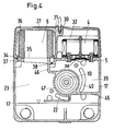
- FIGS. 4 and 5 Further details of the proposed construction can be seen in FIGS. 4 and 5, FIG. 4 being a section along the line BB and FIG. 5 being a section along the line CC in FIG. 3.
- the hood 27 enclosing the fine oil separator 6 and the air intake filter 4 is divided into two chambers 31, 32 by an intermediate wall 30.
- the oil fine separator 6 is arranged in a sealed manner in the left-hand chamber 31 and the air intake filter 4 in the right-hand chamber 32.
- the sealing with respect to the pressure chamber 23 takes place by means of an O-ring 34.
- the pre-oiled mixture rising from the pressure chamber 23 passes through the flange-like surface 26 made opening 35 in the fine separator 6 and flows through the filter elements 36 radially from the inside to the outside.
- the oil running off in the filter elements 36 collects in an annular groove 37 arranged in the surface 26, which is connected to the suction chamber 39 via a throttle bore 38.
- the air sucked in via the air intake filter 4 passes through the non-return flap 5 in the opening 50 into the suction chamber 39 and from there via the opening 40 arranged in the flange area into the intake duct 41 of the compressor 1.
- After sweeping over the edge "inlet closes" the in Air enclosed in the cell compresses and the oil is injected in the region of the first closed cell 42 via a chamber 43. After compression, the air-oil mixture is pushed out via the outlet channel 44 and reaches the pressure chamber 23 of the oil separating container 17 via the opening 22.
- the housing of the oil separator 17 is divided into the aforementioned suction 39 and pressure chamber 23 via an intermediate wall 46.
- this partition 46 merges into a funnel-shaped housing element 47.
- This housing element 47 extends from the flange area of the compressor 1 to the flange area of the electric motor 3 across the oil separator container 17.
- the housing element 17 is reinforced and closed for receiving the bearing 33 of the rotor shaft 20 of the compressor 1.
- the coupling 10 and the pin of the output shaft 19 of the electric motor 3 and the pin of the rotor shaft 20 of the compressor 1 are arranged in the cavity of the funnel-shaped housing element 47.
Landscapes
- Engineering & Computer Science (AREA)
- Mechanical Engineering (AREA)
- General Engineering & Computer Science (AREA)
- Applications Or Details Of Rotary Compressors (AREA)
Applications Claiming Priority (2)
| Application Number | Priority Date | Filing Date | Title |
|---|---|---|---|
| DE4135442 | 1991-10-23 | ||
| DE4135442A DE4135442C1 (fr) | 1991-10-23 | 1991-10-23 |
Publications (2)
| Publication Number | Publication Date |
|---|---|
| EP0538973A1 true EP0538973A1 (fr) | 1993-04-28 |
| EP0538973B1 EP0538973B1 (fr) | 1995-09-06 |
Family
ID=6443543
Family Applications (1)
| Application Number | Title | Priority Date | Filing Date |
|---|---|---|---|
| EP92250305A Expired - Lifetime EP0538973B1 (fr) | 1991-10-23 | 1992-10-19 | Ensemble compresseur avec refroidissement par air |
Country Status (2)
| Country | Link |
|---|---|
| EP (1) | EP0538973B1 (fr) |
| DE (2) | DE4135442C1 (fr) |
Cited By (6)
| Publication number | Priority date | Publication date | Assignee | Title |
|---|---|---|---|---|
| EP1026403A2 (fr) * | 1999-02-01 | 2000-08-09 | Seiko Seiki Kabushiki Kaisha | Compresseur à gaz avec un séparateur d'huile |
| WO2004033912A1 (fr) * | 2002-10-10 | 2004-04-22 | Compair Uk Limited | Compresseur rotatif |
| WO2013126970A1 (fr) | 2012-02-28 | 2013-09-06 | Atlas Copco Airpower, Naamloze Vennootschap | Compresseur à vis |
| WO2017092795A1 (fr) * | 2015-12-01 | 2017-06-08 | Ateliers Busch S.A. | Pompe a vide avec element filtrant |
| US10151313B2 (en) | 2012-02-28 | 2018-12-11 | Atlas Copco Airpower, Naamloze Vennootschap | Compressor device as well as the use of such a compressor device |
| US11015602B2 (en) | 2012-02-28 | 2021-05-25 | Atlas Copco Airpower, Naamloze Vennootschap | Screw compressor |
Families Citing this family (6)
| Publication number | Priority date | Publication date | Assignee | Title |
|---|---|---|---|---|
| DE19707222C2 (de) * | 1997-02-24 | 1998-12-03 | Maid Ludwig | Verdichteranlage |
| DE19711117C1 (de) | 1997-03-05 | 1998-09-03 | Mannesmann Ag | Anlage zum Verdichten eines gasförmigen Mediums oder zur Erzeugung eines Vakuum |
| DE19942265A1 (de) * | 1999-09-04 | 2001-03-08 | Alup Kompressoren Gmbh | Verdichteranlage und Verfahren zur Verdichtung eines Gases |
| GB0905453D0 (en) | 2009-03-30 | 2009-05-13 | British Telecomm | Air compressor |
| DE102011014961A1 (de) * | 2011-03-24 | 2012-09-27 | Rotorcomp Verdichter Gmbh | Schraubenverdichteranlage |
| DE102016100963A1 (de) * | 2016-01-21 | 2017-07-27 | Knorr-Bremse Systeme für Schienenfahrzeuge GmbH | Luftversorgungsanlage |
Citations (4)
| Publication number | Priority date | Publication date | Assignee | Title |
|---|---|---|---|---|
| GB2020362A (en) * | 1978-03-13 | 1979-11-14 | Imi Fluidair Ltd | Rotary compressor |
| EP0063656A1 (fr) * | 1979-05-17 | 1982-11-03 | Ingersoll-Rand Company | Ensemble séparateur air/huile et réservoir d'huile |
| DD203599C2 (de) * | 1982-03-03 | 1988-01-27 | Komb Pumpen Und Verdichter Wis | Luftverdichteraggregat mit oelabscheidung |
| EP0412948A2 (fr) * | 1989-08-10 | 1991-02-13 | GALILEO VACUUM TEC S.p.A. | Système pour démonter rapidement des pompes rotatives à vide |
Family Cites Families (3)
| Publication number | Priority date | Publication date | Assignee | Title |
|---|---|---|---|---|
| GB1318884A (en) * | 1969-07-29 | 1973-05-31 | Hydrovane Compressor | Rotary compressors |
| DE3517493A1 (de) * | 1985-05-15 | 1986-11-20 | Mahle Gmbh, 7000 Stuttgart | In einem kompakten gehaeuse angeordnete schraubenverdichter-anlage |
| DE3521977A1 (de) * | 1985-06-20 | 1987-01-02 | Mahle Gmbh | Kompakte luftverdichteranlage, insbesondere mit einem schraubenrotorenverdichter |
-
1991
- 1991-10-23 DE DE4135442A patent/DE4135442C1/de not_active Expired - Fee Related
-
1992
- 1992-10-19 DE DE59203565T patent/DE59203565D1/de not_active Expired - Fee Related
- 1992-10-19 EP EP92250305A patent/EP0538973B1/fr not_active Expired - Lifetime
Patent Citations (4)
| Publication number | Priority date | Publication date | Assignee | Title |
|---|---|---|---|---|
| GB2020362A (en) * | 1978-03-13 | 1979-11-14 | Imi Fluidair Ltd | Rotary compressor |
| EP0063656A1 (fr) * | 1979-05-17 | 1982-11-03 | Ingersoll-Rand Company | Ensemble séparateur air/huile et réservoir d'huile |
| DD203599C2 (de) * | 1982-03-03 | 1988-01-27 | Komb Pumpen Und Verdichter Wis | Luftverdichteraggregat mit oelabscheidung |
| EP0412948A2 (fr) * | 1989-08-10 | 1991-02-13 | GALILEO VACUUM TEC S.p.A. | Système pour démonter rapidement des pompes rotatives à vide |
Cited By (19)
| Publication number | Priority date | Publication date | Assignee | Title |
|---|---|---|---|---|
| EP1026403A2 (fr) * | 1999-02-01 | 2000-08-09 | Seiko Seiki Kabushiki Kaisha | Compresseur à gaz avec un séparateur d'huile |
| EP1026403A3 (fr) * | 1999-02-01 | 2002-01-02 | Seiko Seiki Kabushiki Kaisha | Compresseur à gaz avec un séparateur d'huile |
| US6478551B1 (en) | 1999-02-01 | 2002-11-12 | Seiko Instruments Inc. | Gas compressor having enlarged discharge chamber |
| WO2004033912A1 (fr) * | 2002-10-10 | 2004-04-22 | Compair Uk Limited | Compresseur rotatif |
| US9850896B2 (en) | 2012-02-28 | 2017-12-26 | Atlas Copco Airpower, Naamloze Vennootschap | Screw compressor |
| US10197058B2 (en) | 2012-02-28 | 2019-02-05 | Atlas Copco Airpower, Naamloze Vennootschap | Screw compressor |
| US11015602B2 (en) | 2012-02-28 | 2021-05-25 | Atlas Copco Airpower, Naamloze Vennootschap | Screw compressor |
| EP3228867A1 (fr) * | 2012-02-28 | 2017-10-11 | Atlas Copco Airpower N.V. | Compresseur à vis |
| WO2013126970A1 (fr) | 2012-02-28 | 2013-09-06 | Atlas Copco Airpower, Naamloze Vennootschap | Compresseur à vis |
| US10151313B2 (en) | 2012-02-28 | 2018-12-11 | Atlas Copco Airpower, Naamloze Vennootschap | Compressor device as well as the use of such a compressor device |
| EP2839160B1 (fr) * | 2012-02-28 | 2018-12-19 | ATLAS COPCO AIRPOWER, naamloze vennootschap | Compresseur à vis |
| US10480511B2 (en) | 2012-02-28 | 2019-11-19 | Atlas Copco Airpower, Naamloze Vennootschap | Screw compressor |
| WO2017092795A1 (fr) * | 2015-12-01 | 2017-06-08 | Ateliers Busch S.A. | Pompe a vide avec element filtrant |
| EP3663585A1 (fr) * | 2015-12-01 | 2020-06-10 | Ateliers Busch S.A. | Pompe à vide avec element filtrant |
| RU2730191C2 (ru) * | 2015-12-01 | 2020-08-19 | Ателье Буш Са | Вакуумный насос и патрон для вакуумного насоса |
| AU2016363589B2 (en) * | 2015-12-01 | 2020-12-10 | Ateliers Busch Sa | Vacuum pump with filtering element |
| WO2017093441A1 (fr) * | 2015-12-01 | 2017-06-08 | Ateliers Busch Sa | Pompe a vide avec element filtrant |
| AU2020281134B2 (en) * | 2015-12-01 | 2022-04-21 | Ateliers Busch Sa | Vacuum pump with filtering element |
| US11319958B2 (en) | 2015-12-01 | 2022-05-03 | Ateliers Busch Sa | Filtering element and associated mounting device for vacuum pump |
Also Published As
| Publication number | Publication date |
|---|---|
| EP0538973B1 (fr) | 1995-09-06 |
| DE4135442C1 (fr) | 1993-04-01 |
| DE59203565D1 (de) | 1995-10-12 |
Similar Documents
| Publication | Publication Date | Title |
|---|---|---|
| DE112006001283B4 (de) | Kältemittelverdichter vom Scroll-Typ | |
| DE10248926B4 (de) | Kompressor | |
| DE69310996T2 (de) | Drehkolbenverdichter | |
| EP3298241B1 (fr) | Pompe à vide à palettes lubrifiée à l'huile munie d'un dispositif de séparation et de recyclage de l'huile | |
| DE69006453T2 (de) | Schmierölrückgewinnungssystem. | |
| EP0538973B1 (fr) | Ensemble compresseur avec refroidissement par air | |
| DE60128387T2 (de) | Hermetischer verdichter | |
| EP0156951B1 (fr) | Pompe à vide avec deux arbres et avec obtention du vide de l'espace d'engrenage | |
| DE2529317A1 (de) | Schraubenkompressor | |
| DE3149245C2 (fr) | ||
| EP3482078B1 (fr) | Pompe à vide à tiroir rotatif lubrifiée à l'huile | |
| DE2833167A1 (de) | Baueinheit, bestehend aus einer oelpumpe zur oelumlaufschmierung einer brennkraftmaschine und einer vakuumpumpe zur erzeugung eines vakuums fuer die bremskraftverstaerkung in kraftfahrzeugen | |
| DE2938557A1 (de) | Verdichteranlage | |
| EP1770281B1 (fr) | Compresseur pour fluide réfrigérant | |
| EP0183813B1 (fr) | Agregat compresseur a anneau liquide | |
| DE4341720C1 (de) | Einstufiger Flügelzellenverdichter | |
| DE19739279C2 (de) | Kompressor-Anlage | |
| DE2332411B2 (de) | Rotationskolbenverdichter | |
| DE1293386B (de) | Drehkolbenverdichter oder -Vakuumpumpe | |
| DE19711117C1 (de) | Anlage zum Verdichten eines gasförmigen Mediums oder zur Erzeugung eines Vakuum | |
| DE3430650A1 (de) | Hermetisch verschlossener umlaufkompressor | |
| DE7927054U1 (de) | Verdichteranlage | |
| EP4170173A1 (fr) | Compresseur à vis avec canaux de lubrification des paliers | |
| DE949250C (de) | Luftgekuehlter Kompressor | |
| EP4407152A1 (fr) | Module de refoulement d'huile destiné à alimenter un groupe d'un véhicule automobile |
Legal Events
| Date | Code | Title | Description |
|---|---|---|---|
| PUAI | Public reference made under article 153(3) epc to a published international application that has entered the european phase |
Free format text: ORIGINAL CODE: 0009012 |
|
| AK | Designated contracting states |
Kind code of ref document: A1 Designated state(s): DE FR GB IT NL SE |
|
| 17P | Request for examination filed |
Effective date: 19930225 |
|
| 17Q | First examination report despatched |
Effective date: 19940415 |
|
| GRAA | (expected) grant |
Free format text: ORIGINAL CODE: 0009210 |
|
| AK | Designated contracting states |
Kind code of ref document: B1 Designated state(s): DE FR GB IT NL SE |
|
| ET | Fr: translation filed | ||
| REF | Corresponds to: |
Ref document number: 59203565 Country of ref document: DE Date of ref document: 19951012 |
|
| ITF | It: translation for a ep patent filed | ||
| GBT | Gb: translation of ep patent filed (gb section 77(6)(a)/1977) |
Effective date: 19951102 |
|
| PLBE | No opposition filed within time limit |
Free format text: ORIGINAL CODE: 0009261 |
|
| STAA | Information on the status of an ep patent application or granted ep patent |
Free format text: STATUS: NO OPPOSITION FILED WITHIN TIME LIMIT |
|
| 26N | No opposition filed | ||
| REG | Reference to a national code |
Ref country code: GB Ref legal event code: IF02 |
|
| PGFP | Annual fee paid to national office [announced via postgrant information from national office to epo] |
Ref country code: GB Payment date: 20041008 Year of fee payment: 13 |
|
| PGFP | Annual fee paid to national office [announced via postgrant information from national office to epo] |
Ref country code: FR Payment date: 20041019 Year of fee payment: 13 Ref country code: NL Payment date: 20041019 Year of fee payment: 13 |
|
| PGFP | Annual fee paid to national office [announced via postgrant information from national office to epo] |
Ref country code: SE Payment date: 20041025 Year of fee payment: 13 |
|
| PGFP | Annual fee paid to national office [announced via postgrant information from national office to epo] |
Ref country code: DE Payment date: 20041222 Year of fee payment: 13 |
|
| PG25 | Lapsed in a contracting state [announced via postgrant information from national office to epo] |
Ref country code: IT Free format text: LAPSE BECAUSE OF NON-PAYMENT OF DUE FEES;WARNING: LAPSES OF ITALIAN PATENTS WITH EFFECTIVE DATE BEFORE 2007 MAY HAVE OCCURRED AT ANY TIME BEFORE 2007. THE CORRECT EFFECTIVE DATE MAY BE DIFFERENT FROM THE ONE RECORDED. Effective date: 20051019 Ref country code: GB Free format text: LAPSE BECAUSE OF NON-PAYMENT OF DUE FEES Effective date: 20051019 |
|
| PG25 | Lapsed in a contracting state [announced via postgrant information from national office to epo] |
Ref country code: SE Free format text: LAPSE BECAUSE OF NON-PAYMENT OF DUE FEES Effective date: 20051020 |
|
| PG25 | Lapsed in a contracting state [announced via postgrant information from national office to epo] |
Ref country code: NL Free format text: LAPSE BECAUSE OF NON-PAYMENT OF DUE FEES Effective date: 20060501 |
|
| PG25 | Lapsed in a contracting state [announced via postgrant information from national office to epo] |
Ref country code: DE Free format text: LAPSE BECAUSE OF NON-PAYMENT OF DUE FEES Effective date: 20060503 |
|
| EUG | Se: european patent has lapsed | ||
| GBPC | Gb: european patent ceased through non-payment of renewal fee |
Effective date: 20051019 |
|
| PG25 | Lapsed in a contracting state [announced via postgrant information from national office to epo] |
Ref country code: FR Free format text: LAPSE BECAUSE OF NON-PAYMENT OF DUE FEES Effective date: 20060630 |
|
| NLV4 | Nl: lapsed or anulled due to non-payment of the annual fee |
Effective date: 20060501 |
|
| REG | Reference to a national code |
Ref country code: FR Ref legal event code: ST Effective date: 20060630 |