EP0533929B1 - Composite roll for use in rolling and manufacture thereof - Google Patents
Composite roll for use in rolling and manufacture thereof Download PDFInfo
- Publication number
- EP0533929B1 EP0533929B1 EP91911197A EP91911197A EP0533929B1 EP 0533929 B1 EP0533929 B1 EP 0533929B1 EP 91911197 A EP91911197 A EP 91911197A EP 91911197 A EP91911197 A EP 91911197A EP 0533929 B1 EP0533929 B1 EP 0533929B1
- Authority
- EP
- European Patent Office
- Prior art keywords
- outer layer
- carbide
- roll
- molten metal
- layer portion
- Prior art date
- Legal status (The legal status is an assumption and is not a legal conclusion. Google has not performed a legal analysis and makes no representation as to the accuracy of the status listed.)
- Expired - Lifetime
Links
Images


Classifications
-
- C—CHEMISTRY; METALLURGY
- C22—METALLURGY; FERROUS OR NON-FERROUS ALLOYS; TREATMENT OF ALLOYS OR NON-FERROUS METALS
- C22C—ALLOYS
- C22C37/00—Cast-iron alloys
-
- B—PERFORMING OPERATIONS; TRANSPORTING
- B32—LAYERED PRODUCTS
- B32B—LAYERED PRODUCTS, i.e. PRODUCTS BUILT-UP OF STRATA OF FLAT OR NON-FLAT, e.g. CELLULAR OR HONEYCOMB, FORM
- B32B15/00—Layered products comprising a layer of metal
- B32B15/01—Layered products comprising a layer of metal all layers being exclusively metallic
- B32B15/011—Layered products comprising a layer of metal all layers being exclusively metallic all layers being formed of iron alloys or steels
-
- Y—GENERAL TAGGING OF NEW TECHNOLOGICAL DEVELOPMENTS; GENERAL TAGGING OF CROSS-SECTIONAL TECHNOLOGIES SPANNING OVER SEVERAL SECTIONS OF THE IPC; TECHNICAL SUBJECTS COVERED BY FORMER USPC CROSS-REFERENCE ART COLLECTIONS [XRACs] AND DIGESTS
- Y10—TECHNICAL SUBJECTS COVERED BY FORMER USPC
- Y10T—TECHNICAL SUBJECTS COVERED BY FORMER US CLASSIFICATION
- Y10T29/00—Metal working
- Y10T29/49—Method of mechanical manufacture
- Y10T29/49544—Roller making
- Y10T29/4956—Fabricating and shaping roller work contacting surface element
- Y10T29/49563—Fabricating and shaping roller work contacting surface element with coating or casting about a core
-
- Y—GENERAL TAGGING OF NEW TECHNOLOGICAL DEVELOPMENTS; GENERAL TAGGING OF CROSS-SECTIONAL TECHNOLOGIES SPANNING OVER SEVERAL SECTIONS OF THE IPC; TECHNICAL SUBJECTS COVERED BY FORMER USPC CROSS-REFERENCE ART COLLECTIONS [XRACs] AND DIGESTS
- Y10—TECHNICAL SUBJECTS COVERED BY FORMER USPC
- Y10T—TECHNICAL SUBJECTS COVERED BY FORMER US CLASSIFICATION
- Y10T428/00—Stock material or miscellaneous articles
- Y10T428/12—All metal or with adjacent metals
- Y10T428/12493—Composite; i.e., plural, adjacent, spatially distinct metal components [e.g., layers, joint, etc.]
- Y10T428/12771—Transition metal-base component
- Y10T428/12861—Group VIII or IB metal-base component
- Y10T428/12951—Fe-base component
- Y10T428/12958—Next to Fe-base component
- Y10T428/12965—Both containing 0.01-1.7% carbon [i.e., steel]
-
- Y—GENERAL TAGGING OF NEW TECHNOLOGICAL DEVELOPMENTS; GENERAL TAGGING OF CROSS-SECTIONAL TECHNOLOGIES SPANNING OVER SEVERAL SECTIONS OF THE IPC; TECHNICAL SUBJECTS COVERED BY FORMER USPC CROSS-REFERENCE ART COLLECTIONS [XRACs] AND DIGESTS
- Y10—TECHNICAL SUBJECTS COVERED BY FORMER USPC
- Y10T—TECHNICAL SUBJECTS COVERED BY FORMER US CLASSIFICATION
- Y10T428/00—Stock material or miscellaneous articles
- Y10T428/12—All metal or with adjacent metals
- Y10T428/12493—Composite; i.e., plural, adjacent, spatially distinct metal components [e.g., layers, joint, etc.]
- Y10T428/12771—Transition metal-base component
- Y10T428/12861—Group VIII or IB metal-base component
- Y10T428/12951—Fe-base component
- Y10T428/12972—Containing 0.01-1.7% carbon [i.e., steel]
- Y10T428/12979—Containing more than 10% nonferrous elements [e.g., high alloy, stainless]
Definitions
- the present invention relates to a composite roll for rolling comprising a solid phase core material and an outer layer material formed by casting around the core material, and a process for producing the same.
- a high alloy chromium cast iron having suitable wear resistance and cracking resistance and comprising 2 to 3.2 % of C, 12 to 18 % of Cr, 2 % or less of Ni and 2 % or less of Mo or a high alloy grain cast iron comprising 3 to 3.4 % of C, 0.4 to 1.5 % of Cr, 2 to 5 % of Ni and 0.2 to 1.0 % of Mo has hitherto been used as a roll for hot rolling (see "Tekko Zairyo no Mamo (Wear of Steel Material)", Joint Society on Iron and Steel Basic Research, page 16 (1984)).
- Japanese Unexamined Patent Publication (Kokai) No. 58-87249 has proposed a wear-resistant cast iron roll material comprising 2.4 to 3.5 % of C, 6.1 to 14 % of V and alloying elements, that are Cr, Mo, W and Co, for improving the wear resistance.
- EP-A-0 309 587 discloses a wear resistant composite roll having an outer layer consisting of 1.5-3.5% C, 0.3-3% Si, 0.3-1.5% Mn, 2-7% Cr, up to 9% Mo, up to 20% W, 3-15% V, optionally up to 5% Co, and the balance being Fe and residual impurities.
- Wear resistance and crack resistance are important to properties required of the rolling roll of the type described above. Smaller wear contributes to an improvement in the accuracy of sheet thickness of the rolled product and, at the same time, reduces the frequency of replacement of rolls, which in turn contributes to an improvement in the working efficiency.
- the rolling roll When the crack resistance is insufficient, cracking occurs due to the application of thermal or mechanical load during use, which gives rise to a major problem trouble. Therefore, it is strongly desired for the rolling roll to have both the wear resistance and the crack resistance.
- an object of the present invention is to provide a process for producing a composite roll for hot rolling which is excellent in wear resistance and crack resistance, particularly surface roughening resistance.
- Another object of the present invention is to provide a process for the formation of a composite roll which comprises cladding the periphery of a core material with an outer layer material.
- the present inventors have made extensive and intensive studies with a view to attaining the above-described object and, as a result, have found that in order to improve the above-described properties in the composite roll, it is necessary to use a steel having particular constituents and crystal structure and that in the process for the formation of a composite roll, it is important to specify cooling conditions (optionally induction heating conditions) of a molten metal, which has led to the completion of the present invention.
- the subject matter of the present invention resides in a composite roll wherein the outer layer portion of a composite roll comprises a steel comprised of, in terms of % by weight, 1.5 to 2.4% of C, 3 to 6% of V and 10 to 20% of at least one element selected from Cr, Mo and W and optionally at least of 0.05 to 0.20% of Al and 0.02 to 0.10% of Ti as an inoculation material and/or 0.1 to 10% of Co and/or 0.3-1.5% of Si and/or Mn with the balance consisting of Fe and unavoidable impurities, said outer layer portion comprising a metallic structure which has a crystal grain diameter of 30 to 150 ⁇ m and is surrounded by an eutectic carbide crystallized in the grain boundary or a metallic structure wherein a carbide as a primary crystal is further dispersed and crystallized in a matrix structure of said crystal as defined in claim 1.
- a process for producing a composite roll comprising pouring a molten metal comprising the above-described steel constituents in between a refractory frame and a core material, conducting induction heating, cooling and solidifying the poured molten metal by means of a water-cooled mold provided at the lower end of said refractory frame at an average solidification rate of 4 to 50 mm/min to form an outer layer portion and gradually pulling out the peripheral portion integrated with the core material as defined in claim 4.
- the outer layer portion has a structure wherein a hard M 6 C carbide (particularly (Cr, Mo, W) 6 C carbide) is crystallized in the grain boundary of a matrix structure (an austenite structure) of a fine crystal grain or a very dense structure wherein a harder MC carbide (particularly VC carbide) is dispersed within the matrix structure of the outer layer portion, and the matrix structure is hardened by the heat treatment (hardening and tempering) of the roll, so that it is possible to provide a roll having a surface roughening resistance and a wear resistance superior to those of the conventional roll for hot rolling.
- a hard M 6 C carbide particularly (Cr, Mo, W) 6 C carbide
- Fig. 1 is a diagram showing the relationship between the crystal grain diameter and the surface roughness after use of the roll.
- Fig. 2 is a diagram showing the relationship between the average solidification rate and the crystal grain diameter.
- Fig. 3 is a diagram showing a change in the structure in the roll production process according to the present invention.
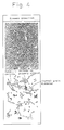
- Fig. 4 is a microphotograph showing the structure of the roll according to the present invention and an explanatory diagram for the microphotograph.
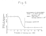
- Fig. 5 is a diagram showing the relationship between the frequency of a heating coil and the state of entrainment of foreign matter.
- Fig. 6 is a partially cross-sectional diagonal view schematically showing an apparatus for practicing the process according to the present invention.
- Fig. 7 is a schematic cross-section showing a principal part of the apparatus shown in Fig. 6.
- the reason why the C content is limited to 1.5 to 2.4% is as follows.
- the C content is less than the lower limit value, the degree of crystallization of a hard carbide is so small that the wear resistance is remarkably deteriorated, which makes it impossible to improve the wear resistance.
- the C content exceeds the upper limit value, the amount of fragile carbide increases. This causes the crack resistance to be spoiled and the toughness to be lowered, so that the object of the present invention cannot be attained.
- the optimum C content for providing both the surface roughening resistance and the wear resistance is in the range of from 1.5 to 2.4%.
- the C content of a material proposed in Japanese Unexamined Patent Publication (Kokai) No. 58-87249 is so high that the wear resistance unfavorably lowers.
- the V content is selected by taking the balance between the V content and the C content into consideration because V causes a MC carbide (VC in the present invention) having a hardness much larger than that of carbides based on a cementite carbide (FeC) or a chromium carbide (Cr 7 C 3 ) to be crystallized.
- the VC carbide is directly crystallized as a primary crystal carbide from molten metal and a most important factor for regulating the structure.
- the C content is in the range of from 1.5 to 2.4%
- the V content is less than the lower limit value, that is, less than 3%, a hard VC-based carbide does not crystallize and unfavorably comes into a matrix structure.
- the V content should fall within the above-described range.
- the eutectic carbide is a very hard M 6 C carbide. Therefore, this carbide can impart a combination of the wear resistance with the toughness to the material.
- the content of at least one element of the above-described three elements should be limited to 10 to 22%.
- the lower limit value is 10% or less, the amount of the hard carbide is so small that the wear resistance becomes insufficient.
- the upper limit value exceeds 22%, the amount of the carbide becomes so large that the surface roughening resistance is spoiled. For this reason, in order for the material to have a combination of the surface roughening resistance with the wear resistance, the content should fall within the above-described range.
- Part of Cr and Mo is distributed in the matrix structure to increase the hardenability and, at the same time, to have a function of conducting precipitation hardening particularly at a high temperature.
- an oxide forming element such as Al or Ti
- an oxide for example, Al 2 O 3 or Ti 2 O 3
- This oxide serves as a nucleus, and a VC carbide crystallizes around the nucleus. Therefore, the oxide forming element is important to the dispersion and crystallization of the VC carbide.
- At least one of Al and Ti should be added in an amount of 0.05 to 0.20% for Al and 0.02 to 0.10% for Ti.
- Si and Mn which are elements useful in a dissolution technique each may be incorporated in an amount of 0.3 to 1.5% for the purpose of conducting deoxidation of the molten metal.
- impurities such as P and S as well may be contained so far as the content is one found in the case of the conventional casting, that is, 0.03% or less. These do not spoil the effect of the present invention.
- Ni is detrimental to the surface roughening resistance in this type of roll, so that the Ni content is desirably 1% or less.
- Co contributes to an improvement in the high-temperature strength and the high-temperature hardness of the matrix within the metallic structure, and the addition of Co in an amount of 0.1 to 10%, preferably 5 to 10%, contributes to a further improvement in the surface roughening resistance and the wear resistance of the roll.
- the matrix structure is tempered and softened. For this reason, in commonly used cast-iron-based rolls comprising a high chromium cast iron, a high alloy grain cast iron or the like, the matrix structure is worn preferentially over the stable carbide even at a high temperature, so that the surface of the roll becomes uneven, which gives rise to surface roughening. Refinement of the matrix structure and crystallization and dispersion of a large amount of a hard carbide in the crystal grain boundary and within the crystal grain are important to the prevention of the surface roughening.
- the present inventors have confirmed that when the surface roughness, Ra ( ⁇ m), of the roll after use is in the range of from 1.6 to 0.3 ⁇ m, the surface roughening of the roll can be prevented and, at the same time, the occurrence of slippage between the roll and the rolled product can be inhibited.
- the crystal grain diameter of the roll structure is in the range of from 30 to 150 ⁇ m.
- Fig. 1 the ordinate represents the surface roughness, Ra ( ⁇ m), and the abscissa represents the crystal grain diameter ( ⁇ m).
- the range of the surface roughness contemplated in the present invention is one defined by the mark ⁇ in the drawing. This drawing indicates that the crystal grain diameter necessary for attaining this surface roughness is in the range of from 30 to 150 ⁇ m.
- a hard M 6 C carbide is crystallized as a eutectic crystal in the crystal grain boundary.
- a very hard MC carbide is crystallized as a primary crystal within a crystal grain of the matrix structure for the purpose of forming a denser structure.
- Fig. 3 is a diagram showing the process of advance of the solidification in the cooling of a molten metal.
- a molten metal (L) (step 1) comprising ingredients according to the present invention is cooled to disperse and crystallize a MC (VC) carbide as a primary crystal from the molten metal.
- the carbide is easily and surely crystallized with an oxide (Al 2 O 3 or the like) formed in the molten metal serving as a nucleus (step 2).
- an austenite ( ⁇ 1 ) is crystallized as a primary crystal around the MC carbide as the primary crystal and grows in a dendrite form (step 3).
- the residual molten metal (L) solidifies in a eutectic crystal form at an eutectic crystallization temperature, so that eutectic M 6 C ((Cr, Mo, W) 6 C) carbides and a eutectic austenite ( ⁇ 2 ) crystallize (step 4).
- the crystal grain diameter is in the range of from 30 to 150 ⁇ m.
- the crystal grain diameter is intended to mean a crystal grain diameter at the time of solidification, that is, as indicated in the step 4, the maximum diameter of a crystal grain surrounded by an eutectic M 6 C carbide crystallized in the crystal grain boundary. Therefore, the structure is such that a hard carbide is crystallized in the crystal grain boundary or within a fine crystal grain.
- the composite roll of the present invention is produced by using an apparatus shown in Figs. 6 and 7.
- a core material 1 in a rod form comprising an alloy steel, such as SCM440, is provided in such a manner that it can be vertically moved.
- a preheating coil 4, a refractory frame 5, an induction heating coil 6 and a water-cooled mold 7 are provided on a platform 3 having an opening through which the core material 1 has been inserted and passed in such a manner that they are coaxially provided in that order from the top about the core material 1.
- the core material 1 is supported by means (not shown) so that it can be moved downward at a constant low speed. In the apparatus, at the outset, the core material 1 is heated by means of the preheating coil 4.
- a molten metal 9 comprising a high speed steel or the like reservoired in a ladle 8 is introduced through a nozzle 8a into an annular space defined by the outer periphery of the preheated core material 1 and the refractory frame 5.
- the heating coil 6 is provided around the refractory frame 5, and the molten metal 9 within the refractory frame 5 is heated by the heating coil 6.
- the lower end of the refractory frame 5 is in contact with the water cooling mold 7, and the molten metal introduced into between the water-cooled mold 7 and the core material 1 is gradually solidified to form an outer layer 2.
- Heating of the molten metal by means of the induction heating coil 6 and cooling by means of the water-cooled mold 7 are most important to the production of a composite roll by using the above-described apparatus. Specifically, the above-described heating is important to welding of the outer periphery of the core material 1 to the outer layer portion 2, and the above-described cooling is important to the formation of a structure having a crystal grain diameter of 30 to 150 ⁇ m.
- the size of the structure is determined by the solidification rate. Therefore, when refinement of the structure through a reduction in the crystal grain diameter is intended, it is necessary to increase the solidification rate.
- the size of the roll has an effect on the crystal grain diameter. For this reason, the crystal grain diameter is about 200 ⁇ m at the smallest in the case of a roll for hot roll finishing.
- the solidification rate can be increased. Specifically, a crystal grain diameter of 30 to 150 ⁇ m corresponding to a roll surface roughness, Ra, of 0.3 to 1.5 pm can be attained by pulling out the core material integrated with the outer layer at a rate of 4 to 50 mm/min.
- Fig. 2 is a graph showing the relationship between the crystal grain diameter ( ⁇ m) (ordinate) and the average solidification rate (mm/min) (abscissa) in Example 2. It suggests that in order to attain a crystal grain diameter of 30 to 150 ⁇ m, it is necessary for the solidification rated to be 4 to 50 mm/min.
- Fig. 4 is a microphotograph of the outer layer portion of a roll produced by a casting process through the use of the above-described casting equipment wherein the molten metal is composed mainly of 2.13% of C, 5.13% of Cr, 6.48% of Mo, 5.31% of V, 4.12% of W and 0.10% of Al and casting is conducted at a solidification rate of 20 mm/min.
- the periphery of the crystal grain having a diameter of 80 ⁇ m is surrounded by an eutectic carbide, and a carbide as a primary crystal is scatteringly present within the matrix.
- the composite roll produced by continuous casting is subjected to a conventional hardening treatment.
- austenite crystallized during solidification becomes a hard martensite and is tempered to give a tempered martensite.
- the composite roll according to the present invention is hard and has a dense structure, it can be very advantageously used as a roll for hot rolling.
- Work rolls for hot roll finishing comprising chemical ingredients specified in the columns for Examples 1, 2 and 3 of the present invention in Table 1 were produced by continuous casting through the use of an apparatus shown in Fig. 6.
- the dissolution was conducted in a high frequency furnace, and steel forging (SCM440) was used as the core material. With respect to heat treatment, casting was followed by annealing, hardening and tempering.
- Example 1 The results of comparison of Examples 1 to 3 of the present invention with Comparative Examples 1 to 5 on specific manufacturing quality and service quality in an actual machine are given in Table 1.
- the crystal grain diameters were 150 ⁇ m, 80 ⁇ m and 50 ⁇ m, respectively, and the surface roughnesses, Ra, after use were 1.6 ⁇ m, 0.9 ⁇ m and 0.5 ⁇ m, respectively. That is, rolls having a very good quality could be produced. Further, no slippage between the roll and the rolled product occurred.
- the composite rolls of the present invention were excellent in the manufacturing quality as well as in the service quality.
- the wear resistance of the composite rolls comprising chemical ingredients falling within the scope of the present invention was 5 times or more that of the conventional rolls. Further, the composite rolls of the present invention had a small surface roughness after use and an improved surface roughening resistance.
- the crystal grain diameters were 150 ⁇ m, 80 ⁇ m and 50 ⁇ m, respectively, and the surface roughnesses, Ra, after use were 1.6 ⁇ m, 0.9 ⁇ m and 0.5 ⁇ m, respectively.
- the results became better with a reduction in the crystal grain diameter.
- the composite rolls of Comparative Examples 4 and 5 were produced by powder metallurgy. In these composite rolls, since the structure is excessively fine, the surface roughness after use was so small that slippage occurred between the roll and the rolled product during rolling. As a result, these comparative composite rolls were unsuitable for use.
- the application of the present invention to a roll for hot rolling makes it possible to provide a high-quality roll having a good wear resistance and free from the occurrence of crack or the like derived from lack of the toughness.
- the roll of the present invention is much superior in the performance to the conventional rolls, which renders the roll of the present invention very useful from the viewpoint of industry.
Landscapes
- Chemical & Material Sciences (AREA)
- Engineering & Computer Science (AREA)
- Materials Engineering (AREA)
- Mechanical Engineering (AREA)
- Metallurgy (AREA)
- Organic Chemistry (AREA)
- Reduction Rolling/Reduction Stand/Operation Of Reduction Machine (AREA)
Applications Claiming Priority (7)
| Application Number | Priority Date | Filing Date | Title |
|---|---|---|---|
| JP15257690 | 1990-06-13 | ||
| JP152576/90 | 1990-06-13 | ||
| JP152577/90 | 1990-06-13 | ||
| JP15257790 | 1990-06-13 | ||
| JP306458/90 | 1990-11-13 | ||
| JP30645890 | 1990-11-13 | ||
| PCT/JP1991/000798 WO1991019824A1 (fr) | 1990-06-13 | 1991-06-13 | Cylindre de laminage composite et procede de fabrication associe |
Publications (3)
| Publication Number | Publication Date |
|---|---|
| EP0533929A1 EP0533929A1 (en) | 1993-03-31 |
| EP0533929A4 EP0533929A4 (show.php) | 1994-04-13 |
| EP0533929B1 true EP0533929B1 (en) | 1997-09-10 |
Family
ID=27320298
Family Applications (1)
| Application Number | Title | Priority Date | Filing Date |
|---|---|---|---|
| EP91911197A Expired - Lifetime EP0533929B1 (en) | 1990-06-13 | 1991-06-13 | Composite roll for use in rolling and manufacture thereof |
Country Status (6)
| Country | Link |
|---|---|
| US (1) | US5419973A (show.php) |
| EP (1) | EP0533929B1 (show.php) |
| KR (1) | KR950006649B1 (show.php) |
| AU (1) | AU650271B2 (show.php) |
| DE (1) | DE69127623T2 (show.php) |
| WO (1) | WO1991019824A1 (show.php) |
Families Citing this family (17)
| Publication number | Priority date | Publication date | Assignee | Title |
|---|---|---|---|---|
| FR2686905B1 (fr) * | 1992-02-04 | 1995-03-24 | Chavanne Ketin | Cylindre de travail composite pour laminage a chaud de produits plats et procede de laminage en comportant application. |
| US5536230A (en) * | 1987-12-23 | 1996-07-16 | Chavanne-Ketin | Composite working roll for hot rolling flat products |
| DE19508947A1 (de) * | 1995-03-13 | 1996-09-19 | Patentstelle Fuer Die Deutsche | Verschleißfeste, anlaßbeständige und warmfeste Legierung |
| DE69818658T2 (de) | 1997-03-18 | 2004-08-12 | Zakrytoe Aktsionernoe Obschestvo "Elmet-Rol-Gruppa Medovara" | Verfahren zur beschichtung mittels des elektroschlackeverfahrens |
| US6669790B1 (en) * | 1997-05-16 | 2003-12-30 | Climax Research Services, Inc. | Iron-based casting alloy |
| RU2149915C1 (ru) * | 1999-02-17 | 2000-05-27 | Брянская государственная инженерно-технологическая академия | Сплав |
| KR101312597B1 (ko) * | 2004-09-13 | 2013-09-30 | 히타치 긴조쿠 가부시키가이샤 | 압연 롤용 원심 주조 외층 및 그 제조 방법 |
| JP4548263B2 (ja) * | 2005-07-29 | 2010-09-22 | Jfeスチール株式会社 | 耐摩耗性に優れた鋳鉄品の製造方法 |
| WO2007077637A1 (ja) * | 2005-12-28 | 2007-07-12 | Hitachi Metals, Ltd. | 遠心鋳造複合ロール |
| DE112007003350A5 (de) * | 2007-02-20 | 2010-02-25 | Siemens Aktiengesellschaft | Bauteil, Vorrichtung zur Verschleißkontrolle für ein Bauteil und Verfahren zur Instandsetzung eines Bauteils |
| JP5025315B2 (ja) * | 2007-04-19 | 2012-09-12 | 株式会社フジコー | 熱間圧延用複合ロール、熱間圧延用複合ロールの製造方法及び熱間圧延方法 |
| JP4922971B2 (ja) * | 2008-03-07 | 2012-04-25 | 株式会社フジコー | 熱間圧延用複合ロール及びその製造方法 |
| KR20140110621A (ko) * | 2013-03-08 | 2014-09-17 | 엘지전자 주식회사 | 선회 또는 고정스크롤용 cv 흑연주철 및 그를 이용한 선회 또는 고정스크롤의 제조방법 |
| KR102060468B1 (ko) | 2013-03-08 | 2019-12-30 | 엘지전자 주식회사 | 베인 펌프 |
| EP3006124B1 (en) * | 2014-10-09 | 2017-12-20 | Centre de Recherches Métallurgiques asbl - Centrum voor Research in de Metallurgie vzw | Work roll manufactured by laser cladding and method therefor |
| JP2023548771A (ja) * | 2020-10-13 | 2023-11-21 | サントル・ドゥ・ルシェルシェ・メタリュルジク・アエスベエル-セントルム・フォール・リサーチ・イン・デ・メタルルージエ・フェーゼットヴェー | レーザークラッディングによる熱間圧延ロールの製造方法 |
| CN113547099A (zh) * | 2021-06-11 | 2021-10-26 | 中钢集团邢台机械轧辊有限公司 | 一种薄板坯全无头轧制用粗轧高速钢工作辊制备方法 |
Family Cites Families (20)
| Publication number | Priority date | Publication date | Assignee | Title |
|---|---|---|---|---|
| JPS5830382B2 (ja) * | 1979-10-26 | 1983-06-29 | 株式会社クボタ | 高クロムワ−クロ−ル |
| FR2493191A1 (fr) * | 1980-10-31 | 1982-05-07 | Usinor | Cydindre de laminage a froid fabrique par coulee et son procede de fabrication |
| JPS5919786B2 (ja) * | 1980-12-25 | 1984-05-08 | 株式会社富士工業所 | 母材の外周に鋳かけ肉盛リクラツド材を形成する方法 |
| JPS5887249A (ja) * | 1981-11-18 | 1983-05-25 | Hitachi Metals Ltd | 耐摩耗鋳鉄ロ−ル材 |
| JPS601392B2 (ja) * | 1982-02-20 | 1985-01-14 | 関東特殊製鋼株式会社 | ピルガ−圧延用ロール材 |
| JPS59153869A (ja) * | 1983-02-21 | 1984-09-01 | Kanto Tokushu Seikou Kk | 非晶質金属圧延用ロ−ル材 |
| JPS60124407A (ja) * | 1983-12-06 | 1985-07-03 | Kubota Ltd | 高バナジウム複合鋳鉄ロ−ル |
| JPS6160256A (ja) * | 1984-08-30 | 1986-03-27 | Hitachi Metals Ltd | 鋳かけ肉盛方法 |
| JPS61199051A (ja) * | 1985-02-28 | 1986-09-03 | Kubota Ltd | 耐ヒ−トクラツク性、耐摩耗性及び耐焼付性に優れた圧延用ロ−ル材 |
| US4596282A (en) * | 1985-05-09 | 1986-06-24 | Xaloy, Inc. | Heat treated high strength bimetallic cylinder |
| US4721153A (en) * | 1986-09-12 | 1988-01-26 | Hitachi Metals, Inc. | High-chromium compound roll |
| US4726417A (en) * | 1986-09-12 | 1988-02-23 | Hitachi Metals, Ltd. | Adamite compound roll |
| JPS63114937A (ja) * | 1986-11-04 | 1988-05-19 | Kubota Ltd | 圧延用複合ロ−ルおよびその外層材 |
| EP0309587B1 (en) * | 1987-03-24 | 1993-07-28 | Hitachi Metals, Ltd. | Abrasion-resistant composite roll and process for its production |
| JPS63266043A (ja) * | 1987-04-23 | 1988-11-02 | Nkk Corp | 熱間圧延用ロ−ル |
| JPH0191901A (ja) * | 1987-10-05 | 1989-04-11 | Hitachi Metals Ltd | 圧延用複合ロールの製造方法 |
| EP0347512A1 (en) * | 1988-06-23 | 1989-12-27 | INNSE CILINDRI S.r.l. | A bimetal construction roll for reducing and finishing stands in a rolling mill train |
| EP0430241B1 (en) * | 1989-11-30 | 1996-01-10 | Hitachi Metals, Ltd. | Wear-resistant compound roll |
| US5225007A (en) * | 1990-02-28 | 1993-07-06 | Hitachi Metals Ltd. | Method for wear-resistant compound roll manufacture |
| US5305522A (en) * | 1991-07-09 | 1994-04-26 | Hitachi Metals, Ltd. | Method of producing a compound roll |
-
1991
- 1991-06-13 AU AU79912/91A patent/AU650271B2/en not_active Ceased
- 1991-06-13 DE DE69127623T patent/DE69127623T2/de not_active Expired - Fee Related
- 1991-06-13 WO PCT/JP1991/000798 patent/WO1991019824A1/ja not_active Ceased
- 1991-06-13 KR KR1019920703212A patent/KR950006649B1/ko not_active Expired - Fee Related
- 1991-06-13 EP EP91911197A patent/EP0533929B1/en not_active Expired - Lifetime
- 1991-06-13 US US07/989,241 patent/US5419973A/en not_active Expired - Fee Related
Also Published As
| Publication number | Publication date |
|---|---|
| AU650271B2 (en) | 1994-06-16 |
| AU7991291A (en) | 1992-01-07 |
| WO1991019824A1 (fr) | 1991-12-26 |
| KR950006649B1 (ko) | 1995-06-21 |
| EP0533929A1 (en) | 1993-03-31 |
| EP0533929A4 (show.php) | 1994-04-13 |
| KR930700693A (ko) | 1993-03-15 |
| DE69127623D1 (de) | 1997-10-16 |
| US5419973A (en) | 1995-05-30 |
| DE69127623T2 (de) | 1998-01-22 |
Similar Documents
| Publication | Publication Date | Title |
|---|---|---|
| US4958422A (en) | Wear-resistant compound roll | |
| EP0533929B1 (en) | Composite roll for use in rolling and manufacture thereof | |
| JP3205745B2 (ja) | 耐摩耗耐焼付性熱間圧延用ロール | |
| EP0560210B1 (en) | Compound roll and method of producing same | |
| US5225007A (en) | Method for wear-resistant compound roll manufacture | |
| JPWO1994022606A1 (ja) | 耐摩耗耐焼付性熱間圧延用ロール | |
| EP0430241B1 (en) | Wear-resistant compound roll | |
| JPWO1988007594A1 (ja) | 耐摩耗複合ロール及びその製造方法 | |
| WO1995007780A1 (en) | Method of manufacturing thin cast piece through continuous casting | |
| EP0911421B1 (en) | Composite work roll for cold rolling | |
| JP4922971B2 (ja) | 熱間圧延用複合ロール及びその製造方法 | |
| JP4354718B2 (ja) | 遠心鋳造製熱間圧延用複合ロール | |
| JP3028514B2 (ja) | 耐摩耗性・耐肌荒れ性等にすぐれた圧延用複合ロール | |
| JP3308058B2 (ja) | 棒鋼圧延用ロール | |
| JPH0778267B2 (ja) | 圧延用複合ロール及びその製造方法 | |
| JPWO1991019824A1 (ja) | 圧延用複合ロール及びその製造方法 | |
| JP2686207B2 (ja) | 圧延用ロール材 | |
| JPH0775808A (ja) | 形鋼圧延用耐摩耗複合ロール | |
| JP3104472B2 (ja) | 熱間圧延用ロール材 | |
| JP3180702B2 (ja) | 連続鋳造方法 | |
| JP3030077B2 (ja) | 耐クラック性に優れた耐摩耗複合ロール及びその製造方法 | |
| JP2004009063A (ja) | 熱間圧延用複合ロール | |
| JPH031371B2 (show.php) | ||
| JP2000158020A (ja) | 耐衝撃性及び耐食性に優れた製鉄圧延設備用複合ロール | |
| JP3679221B2 (ja) | 耐摩耗性に優れた製鉄圧延設備用複合ロール及びその製造方法 |
Legal Events
| Date | Code | Title | Description |
|---|---|---|---|
| PUAI | Public reference made under article 153(3) epc to a published international application that has entered the european phase |
Free format text: ORIGINAL CODE: 0009012 |
|
| 17P | Request for examination filed |
Effective date: 19921215 |
|
| AK | Designated contracting states |
Kind code of ref document: A1 Designated state(s): DE FR GB IT |
|
| A4 | Supplementary search report drawn up and despatched |
Effective date: 19940224 |
|
| AK | Designated contracting states |
Kind code of ref document: A4 Designated state(s): DE FR GB IT |
|
| 17Q | First examination report despatched |
Effective date: 19951030 |
|
| GRAG | Despatch of communication of intention to grant |
Free format text: ORIGINAL CODE: EPIDOS AGRA |
|
| GRAH | Despatch of communication of intention to grant a patent |
Free format text: ORIGINAL CODE: EPIDOS IGRA |
|
| GRAH | Despatch of communication of intention to grant a patent |
Free format text: ORIGINAL CODE: EPIDOS IGRA |
|
| GRAA | (expected) grant |
Free format text: ORIGINAL CODE: 0009210 |
|
| AK | Designated contracting states |
Kind code of ref document: B1 Designated state(s): DE FR GB IT |
|
| REF | Corresponds to: |
Ref document number: 69127623 Country of ref document: DE Date of ref document: 19971016 |
|
| ITF | It: translation for a ep patent filed | ||
| ET | Fr: translation filed | ||
| PLBE | No opposition filed within time limit |
Free format text: ORIGINAL CODE: 0009261 |
|
| STAA | Information on the status of an ep patent application or granted ep patent |
Free format text: STATUS: NO OPPOSITION FILED WITHIN TIME LIMIT |
|
| 26N | No opposition filed | ||
| REG | Reference to a national code |
Ref country code: GB Ref legal event code: IF02 |
|
| PGFP | Annual fee paid to national office [announced via postgrant information from national office to epo] |
Ref country code: FR Payment date: 20040608 Year of fee payment: 14 |
|
| PGFP | Annual fee paid to national office [announced via postgrant information from national office to epo] |
Ref country code: GB Payment date: 20040609 Year of fee payment: 14 |
|
| PGFP | Annual fee paid to national office [announced via postgrant information from national office to epo] |
Ref country code: DE Payment date: 20040624 Year of fee payment: 14 |
|
| PG25 | Lapsed in a contracting state [announced via postgrant information from national office to epo] |
Ref country code: GB Free format text: LAPSE BECAUSE OF NON-PAYMENT OF DUE FEES Effective date: 20050613 Ref country code: IT Free format text: LAPSE BECAUSE OF NON-PAYMENT OF DUE FEES Effective date: 20050613 |
|
| PG25 | Lapsed in a contracting state [announced via postgrant information from national office to epo] |
Ref country code: DE Free format text: LAPSE BECAUSE OF NON-PAYMENT OF DUE FEES Effective date: 20060103 |
|
| PG25 | Lapsed in a contracting state [announced via postgrant information from national office to epo] |
Ref country code: FR Free format text: LAPSE BECAUSE OF NON-PAYMENT OF DUE FEES Effective date: 20060228 |
|
| GBPC | Gb: european patent ceased through non-payment of renewal fee |
Effective date: 20050613 |
|
| REG | Reference to a national code |
Ref country code: FR Ref legal event code: ST Effective date: 20060228 |