EP0528877B1 - Apparat und methode zur analyse von in einer flüssigkeit suspendierten teilchen - Google Patents
Apparat und methode zur analyse von in einer flüssigkeit suspendierten teilchen Download PDFInfo
- Publication number
- EP0528877B1 EP0528877B1 EP91909082A EP91909082A EP0528877B1 EP 0528877 B1 EP0528877 B1 EP 0528877B1 EP 91909082 A EP91909082 A EP 91909082A EP 91909082 A EP91909082 A EP 91909082A EP 0528877 B1 EP0528877 B1 EP 0528877B1
- Authority
- EP
- European Patent Office
- Prior art keywords
- particles
- flow area
- elongated flow
- fluid medium
- cuvette
- Prior art date
- Legal status (The legal status is an assumption and is not a legal conclusion. Google has not performed a legal analysis and makes no representation as to the accuracy of the status listed.)
- Expired - Lifetime
Links
Images






Classifications
-
- G—PHYSICS
- G01—MEASURING; TESTING
- G01N—INVESTIGATING OR ANALYSING MATERIALS BY DETERMINING THEIR CHEMICAL OR PHYSICAL PROPERTIES
- G01N15/00—Investigating characteristics of particles; Investigating permeability, pore-volume or surface-area of porous materials
- G01N15/10—Investigating individual particles
-
- G—PHYSICS
- G01—MEASURING; TESTING
- G01N—INVESTIGATING OR ANALYSING MATERIALS BY DETERMINING THEIR CHEMICAL OR PHYSICAL PROPERTIES
- G01N15/00—Investigating characteristics of particles; Investigating permeability, pore-volume or surface-area of porous materials
- G01N15/10—Investigating individual particles
- G01N15/14—Optical investigation techniques, e.g. flow cytometry
- G01N15/1404—Handling flow, e.g. hydrodynamic focusing
-
- G—PHYSICS
- G01—MEASURING; TESTING
- G01N—INVESTIGATING OR ANALYSING MATERIALS BY DETERMINING THEIR CHEMICAL OR PHYSICAL PROPERTIES
- G01N1/00—Sampling; Preparing specimens for investigation
- G01N1/28—Preparing specimens for investigation including physical details of (bio-)chemical methods covered elsewhere, e.g. G01N33/50, C12Q
- G01N1/38—Diluting, dispersing or mixing samples
-
- G—PHYSICS
- G01—MEASURING; TESTING
- G01N—INVESTIGATING OR ANALYSING MATERIALS BY DETERMINING THEIR CHEMICAL OR PHYSICAL PROPERTIES
- G01N15/00—Investigating characteristics of particles; Investigating permeability, pore-volume or surface-area of porous materials
- G01N15/10—Investigating individual particles
- G01N15/14—Optical investigation techniques, e.g. flow cytometry
- G01N15/1404—Handling flow, e.g. hydrodynamic focusing
- G01N15/1409—Handling samples, e.g. injecting samples
-
- G—PHYSICS
- G01—MEASURING; TESTING
- G01N—INVESTIGATING OR ANALYSING MATERIALS BY DETERMINING THEIR CHEMICAL OR PHYSICAL PROPERTIES
- G01N15/00—Investigating characteristics of particles; Investigating permeability, pore-volume or surface-area of porous materials
- G01N15/10—Investigating individual particles
- G01N2015/1019—Associating Coulter-counter and optical flow cytometer [OFC]
-
- G—PHYSICS
- G01—MEASURING; TESTING
- G01N—INVESTIGATING OR ANALYSING MATERIALS BY DETERMINING THEIR CHEMICAL OR PHYSICAL PROPERTIES
- G01N15/00—Investigating characteristics of particles; Investigating permeability, pore-volume or surface-area of porous materials
- G01N15/10—Investigating individual particles
- G01N15/1031—Investigating individual particles by measuring electrical or magnetic effects
- G01N15/12—Investigating individual particles by measuring electrical or magnetic effects by observing changes in resistance or impedance across apertures when traversed by individual particles, e.g. by using the Coulter principle
- G01N2015/135—Electrodes
-
- G—PHYSICS
- G01—MEASURING; TESTING
- G01N—INVESTIGATING OR ANALYSING MATERIALS BY DETERMINING THEIR CHEMICAL OR PHYSICAL PROPERTIES
- G01N15/00—Investigating characteristics of particles; Investigating permeability, pore-volume or surface-area of porous materials
- G01N15/10—Investigating individual particles
- G01N15/14—Optical investigation techniques, e.g. flow cytometry
- G01N15/1404—Handling flow, e.g. hydrodynamic focusing
- G01N2015/1418—Eliminating clogging of debris
-
- G—PHYSICS
- G01—MEASURING; TESTING
- G01N—INVESTIGATING OR ANALYSING MATERIALS BY DETERMINING THEIR CHEMICAL OR PHYSICAL PROPERTIES
- G01N21/00—Investigating or analysing materials by the use of optical means, i.e. using sub-millimetre waves, infrared, visible or ultraviolet light
- G01N21/62—Systems in which the material investigated is excited whereby it emits light or causes a change in wavelength of the incident light
- G01N21/63—Systems in which the material investigated is excited whereby it emits light or causes a change in wavelength of the incident light optically excited
- G01N21/64—Fluorescence; Phosphorescence
-
- Y—GENERAL TAGGING OF NEW TECHNOLOGICAL DEVELOPMENTS; GENERAL TAGGING OF CROSS-SECTIONAL TECHNOLOGIES SPANNING OVER SEVERAL SECTIONS OF THE IPC; TECHNICAL SUBJECTS COVERED BY FORMER USPC CROSS-REFERENCE ART COLLECTIONS [XRACs] AND DIGESTS
- Y10—TECHNICAL SUBJECTS COVERED BY FORMER USPC
- Y10S—TECHNICAL SUBJECTS COVERED BY FORMER USPC CROSS-REFERENCE ART COLLECTIONS [XRACs] AND DIGESTS
- Y10S436/00—Chemistry: analytical and immunological testing
- Y10S436/805—Optical property
-
- Y—GENERAL TAGGING OF NEW TECHNOLOGICAL DEVELOPMENTS; GENERAL TAGGING OF CROSS-SECTIONAL TECHNOLOGIES SPANNING OVER SEVERAL SECTIONS OF THE IPC; TECHNICAL SUBJECTS COVERED BY FORMER USPC CROSS-REFERENCE ART COLLECTIONS [XRACs] AND DIGESTS
- Y10—TECHNICAL SUBJECTS COVERED BY FORMER USPC
- Y10S—TECHNICAL SUBJECTS COVERED BY FORMER USPC CROSS-REFERENCE ART COLLECTIONS [XRACs] AND DIGESTS
- Y10S436/00—Chemistry: analytical and immunological testing
- Y10S436/806—Electrical property or magnetic property
Definitions
- the present invention relates to an apparatus and a method for analyzing particles suspended in a fluid medium or liquid, which particles emit radiation characteristic of the particles when exposed to radiation.
- the invention relates particularly to analyzing biological cells by means of flow cytometry, more particularly to flow cytometrically analyzing biological cells which are labelled with a fluorescent antibody or which are anti-fluorescent.
- antigenic determinants which are specific to the cells in question.
- antigenic determinants are common to different cells, which antigenic determinants may be used as the basis for a general classification.
- Antibodies of both of the above-mentioned types may be used for fluorescent-microscopically analyzing cells after conjugation with a suitable fluorochrome, particularly of the type having green and red fluorescence, e.g. FITC (fluorescein isothiocyanate) and TRITC (trimethyl rhodamine isothiocyanat), respectively.
- FITC fluorescein isothiocyanate
- TRITC trimethyl rhodamine isothiocyanat
- Intracellular enzymes may be demonstrated after their reaction with substrate analogues, the cleavage of which results in the formation of a fluorescent product (fluorescein diacetate, methyl umbelly furones).
- substrate analogues fluorescein diacetate, methyl umbelly furones
- ligands are often involved in intercellular recognition and control operations. Fluorescence-labelled ligands (or ligand analogues) may be used for detecting receptors of this type.
- bacteria and algae posses auto-fluorescent properties.
- the use of fluorescence spectrophotometry is particularly relevant in connection with the examination of subgroups of the type of cells which can only be distinguished from one another by means of superficial markers which are visualized by means of antibodies.
- lymphocytes of peripheral blood These lymphocyes are dividable into T and B lymphocytes which cannot be separated from one another on the basis of morphological criterions, but on the basis of functional and antigenic differences.
- the B cells can produce antibodies. These antibodies are exposed on the surface of the B cells and can be utilized for classification by the use of anti-antibodies.
- the T cells fulfil a number of different functions, both in the control of the immune apparatus and in the direct execution of the cellular immunity.
- the T cells can be divided into a number of subgroups by monoclonal antibodies. Consequently, the examination of the distribution on the various subgroups is relevant in all instances involving the function of the immune apparatus in the broadest sense.
- the above-mentioned subgroups partly overlap one another. Consequently, it is important to be able to examine two or more surface determinants at the same time, i.e. individual stimulus and detection of two or more fluorochromes as indicated above.
- Conditions where these kinds of examinations are of interest are among others conditions of immune deficiency, autoimmune diseases, leucemia and other malignant diseases.
- the presently commercially available apparatuses are very complicated and expensive, and they are generally based upon a general principle according to which the fluid medium is passed through a small aperture, in which fluid medium fluorescence-labelled biological particles to be analyzed are suspended, around which aperture a carrier fluid is passing so as to produce a carrier-fluid stabilized laminar flow of the fluid medium in which the particles to be analyzed are suspended.
- the laminar flow is exposed to radiation in a direction defining an angle relative to the direction of flow of the fluid medium by means of a constantly luminous laser lamp, such as an argon laser, and the fluorescence of all the particles fluorescent when influenced by the monochromic light of the laser is picked-up, e.g. at an angle of 90°, and is analysed.
- a constantly luminous laser lamp such as an argon laser
- 0 068 404 discloses an example of the application of two electrodes in connection with a laminar flow, however, the electric field established by the generation of a voltage across the two electrodes is not well-defined and does not offer the possibility of an accurate counting nor a volume fluid determination.
- Cuvettes having a flow area in the form of a capillary passage are well-known within the art and may be utilized for measuring colour absorption of fluids which do not contain particles that may block the capillary passage.
- An example of this type of cuvette is disclosed in EP patent no. 0 158 948, which discloses a flow cuvette assembled from two cuvette body halves, in which the even surfaces, which are positioned adjacent one another when the cuvette is assembled, are provided with grooves of the surfaces of the joining surfaces and comprise a flat chamber arranged in a central part.
- This prior art cuvette is intended for volumes of the order of nanoliters and may, particularly due to the small dimensions of the analysis chamber in one direction, only be utilized for analyzing particlefree fluids, as is clearly stated in said patent.
- the two-part cuvette is secured by means of a spring device, and by release of the spring device the two cuvette body halves will drop randomly so that they must be positioned manually when the cuvette is to be reassembled.
- a through-flow cuvette adapted to high-pressure liquid chromatography is known.
- the technical field of high-pressure liquid chromatography is, however, highly different from the technical field of analyzing particles suspended in a fluid medium such as the technique of analyzing biological cells by means of flow cytometry. Therefore, the high-pressure liquid chromatography through-flow cuvette known from the above US patent is not readily adaptable to the technique of analyzing particles suspended in a fluid medium or liquid such as analyzing biological cells by means of flow cytometry.
- the above US patent includes no indications regarding possible technical solutions to the problem of eliminating the generation of obstacles or blocking of a cuvette of an apparatus for analyzing particles suspended in a fluid medium or liquid.
- a flow cell composed of a plurality of segments is known.
- the flow cell of the above US patent is adapted to be easily disassembled in order to permit cleaning or removal of obstacles of the passage of a flow cell.
- the technical solution to the problem of permitting cleaning or removal of obstacles of the passage of the flow cell of the above US patent is, however, totally different from the solution to the similar problem in accordance with the teachings of the present invention as will be evident from the below description. From US patent no.
- a flow cell comprising a small flow passage provided by a permanent joining of the two cuvette body halves having grooves on their joining surfaces.
- This prior art flow cell is solely intended for photometrically analyzing liquids which do not contain particles that may block the flow passage, and the two flow cell body halves are not adapted to be separated once assembled. The photometric measurement is established by submitting light through a flow passage in a direction coincident with the flow direction of the liquid.
- the present invention provides an apparatus and a method suitable for analyzing fluorescence-labelled or autofluorescent particles of cells suspended in a liquid, which apparatus, however, does not suffer from the disadvantages of the above-mentioned prior art apparatuses, which rely on an expensive laser lamp, and by which the fluid medium must be fed from a feeding pipe having a small aperture, from which the fluid medium is supported by an exterior carrier fluid. Accordingly, the invention provides the possibility of utilizing a low-energy light source, e.g. a iodine quartz photoflood lamp of e.g. only 100 W, or a flash lamp, e.g. a xenon flash lamp.
- a low-energy light source e.g. a iodine quartz photoflood lamp of e.g. only 100 W
- a flash lamp e.g. a xenon flash lamp.
- the apparatus and the method according to the invention it is possible to combine spectrophotometrically fluorescence-analyzing technique and counting and a determination of the sizes of the particles to be analyzed, which counting and determination of the sizes of the particles are based on a modified Coulter-principle.
- a fluid medium containing a fluid medium in which biological particles are suspended through a passage having the dimensions of a capillary passage providing a highly reduced risk of blocking the passage and providing a simple cleaning capability, in the event blocking occurs.
- the utilization of a passage having small cross-sectional dimensions provides a particular advantage in that the particles to be analyzed sequentially arrive at the measuring area individually, which is not possible by the aforementioned laminar flow technique comprising a carrier fluid.
- the particles arrive at the measuring area as close to one another as possible without coincidence, i.e. coincidence of measurements from more particles, thus increasing the measuring rate as compared to the prior art technique.
- the liquid containing the particles to be analyzed pass through the flow system as a laminar flow of constant rate without utilizing a carrier fluid.
- the invention is to be explained in greater details below, particularly relating to flow-cytometrically analyzing biological cells which are flourescent having a characteristic fluorescent radiation when subjected to illumination, it is, however, to be understood that the invention is also appliable in connection with a so-called light scatter or other analyzing methods based upon incident radiation, by which the relevant particles emit radiation characteristic of these particles.
- the invention will be explained particularly in relation to a fluid medium in which biological cells to be analyzed are suspended, which fluid medium is passed through a passage having cross-sectional dimensions adapted to the size of the cells, and which fluid medium is exposed to light for illuminating the cells individually. Consequently, the existence of an elongated flow area having the dimensions of a capillary passage is mandatory, however, causing problems as regards blocking of the passage.
- the principles and the techniques according to the invention are considered generally applicable as they may be utilized for substantially bigger, non-biological particles, provided that the particles are capable of emitting a characteristic radiation when exposed to radiation.
- a unique technique is provided, which is well-suited for the aforesaid analyzing of particular cell populations comprising subgroups of cell types which can only be distinguished from one another by means of superficial markers exposed by antibodies.
- an apparatus comprising:
- the elongated flow area is provided by the assembling of the cuvette from two component body members, which are adapted to be positioned closely adjoining one another through the respective planar facial surfaces, and in at least one of which the elongated groove is defined, e.g. provided by a milling operation.
- the elongated groove is preferably only provided in one of the facial surfaces. Consequently, the elongated flow area is defined by the groove and the adjoining facial surface of the second body member. It is, however, within the scope of the invention to provide opposite and cooperating grooves in the planar facial surfaces of both body members.
- two cooperation grooves has been found unsuitable due to the possible complications likely to occur when assembling the two body members as the grooves of both body members are to be positioned extremely accurately relative to one another.
- the two body members are adapted to be moved between a first position, in which the planar facial surfaces are positioned adjacent one another in a fluid-tight manner, and a second position, in which the planar facial surfaces are positioned spaced apart.
- the analysis is conducted in a manner to be described in greater details below. Having finished the analysis, the planar facial surfaces are moved relative to one another to the second position, in which the planar facial surfaces and further the feeding and discharging means are cleaned, rinsed or washed, as will be explained below.
- the planar facial surfaces of the body members are also cleaned, rinsed or washed, provided the elongated flow area is blocked unintendedly.
- the first and second body members are movable relative to one another by parallelly displacing at least one of the two body members in a direction perpendicular to the planar facial surfaces of the body members.
- a stop means is provided, which stop means receives the spring loaded body member, when the body members are moved to the second position so as to maintain the springloaded body member in a well-defined position, in which the facial surface of the spring-loaded body member is maintained substantially parallel with the opposite facial surface.
- the means for the feeding of the fluid medium in which particles are suspended is preferably constituted by a feeding channel or passage, which extends from the exterior relative to the cuvette to the inlet aperture of the elongated flow area.
- the means for discharging the fluid medium in which particles are suspended preferably comprises a discharge channel or passage provided in the same or in the other body member, which discharge passage extends from the outlet aperture of the elongated flow area to the exterior relative to the cuvette.
- the feeding passage and the discharge passage may be provided in different body members.
- the feeding passage and the discharge passage are, however, preferably provided in one of the body members exclusively and constituted by respective bores extending between an outer surface of the body member in question and the elongated flow area.
- the bores are preferably provided in the first body member, the facial surface of which is provided with the elongated groove.
- the feeding passage and the discharge passage are provided in the second body member having no elongated groove, it is extremely difficult to ensure that these passages will lead precisely into the elongated flow area, when the body members have been opened and reclosed, and will also cause optical problems as will be understood from the description below.
- At least one of the body members is transparent to the radiation to which the particles are exposed, and at least one of the body members is transparent to the radiation emitted by the particles. Consequently, at least one of the body members is preferably transparent and is preferably made from quartz glass.
- the first body member i.e. the body member the facial surface of which is provided with the elongated groove and the body member preferably comprising the feeding and discharge passages needs not to be transparent, but is preferably also made from quartz glass.
- the elongated flow area defined between the two body members of the cuvette constitutes a capillary passage as explained above and preferably has the shape of a geometrical section of a rectilinear cylinder having a circular cross-section of a radius of curvature not exceeding 1 mm, preferably not exceeding 100 »m, most preferably 50 »m, and having a depth not exceeding 1 mm, preferably not exceeding 100 »m, and most preferably 30-35 »m.
- This dimension of the passage is suitable for biological cells having a diameter of the order of 8-15 »m, which is the normal size of some lymphocytes.
- the above-mentioned dimensions of the elongated flow area have been defined on the basis that the particles are to arrive at the measuring area individually whenever possible, and the cross-sectional dimension of the elongated flow area is consequently determined in consideration of the particles to be analyzed. It is not required that the particles pass individually and sequentially through the feeding passage.
- the feeding passage preferably has dimensions that are far larger than those of the elongated flow area. Experiments have, however, revealed that the bore constituting the feeding passage should preferably not be larger than e.g. 3 mm, since larger dimensions make it difficult to ensure that the particles arrive at the elongated flow area homogeneously. Provided the diameter of the feeding passage is less than 3 mm, a capillary passage effect occurs and a risk of blocking the feeding passage exists.
- the problem of eliminating blocking of the feeding passage is solved by means of an agitating means.
- the feeding passage is constituted by a bore of a diameter not exceeding 3 mm, preferably not exceeding 2 mm, particularly of the order of 1 mm, extending through one of the body members, preferably the first body member, through which bore a flexible wire body extends, which is rotatable relative to its longitudinal axis, one end portion of which wire body is connected to a wire rotating means, and the opposite end portion of which wire body extends into the elongated flow area.
- the wire body preferably contacts the facial surface of the elongated flow area channel opposite to the inlet aperture of the elongated flow area.
- the flexible wire body may have a non-circular cross-section, particularly a polygonal, particularly a tetragonal or triangular cross section, preferably a square cross section having a lateral dimension of the order of 0.2-0.5 mm, particularly of 0.3 mm when the bore constituting the feeding passage has a diameter of the order of 1 mm.
- the flexible wire body may have a circular cross section of a cross-sectional dimension of 0.2-0.5 mm, and particularly of 0.3 mm.
- This wire body has been found to provide an advantageous agitation, and it is distinguished by providing a uniform movement, which is less liable to cause mechanical or electrical disturbances or noise than a polygonal-shaped wire body.
- the flexible wire body is preferably made from a plastic material which only swells insignificantly in water under the prevailing conditions, e.g. nylon, polypropylene, polycarbonate or Teflon.
- This type of agitating means comprising a wire, which is rotatable relative to its longitudinal axis, and which is arranged in the feeding passage constituted by a bore of the above-mentioned dimensions, has not been disclosed previously within the prior art constituting an agitating device for agitating particles suspended in a liquid.
- this wire body has proved capable of avoiding any agglomeration of biological cells, capable of avoiding that the particles stick to the the surface of the passage and capable of ensuring that the particles are distributed homogenously at the inlet aperture of the elongated flow area.
- the wire body has a non-circular cross section, particularly a polygonal, preferably a tetragonal or triangular cross section, most preferably a square cross section of the above-mentioned dimensions.
- a non-circular cross section particularly a polygonal, preferably a tetragonal or triangular cross section, most preferably a square cross section of the above-mentioned dimensions.
- the wire body When rotation about its longitudinal axis, the wire body more or less assumes the shape of a spiral.
- the wire body may rotate clockwise or counter-clockwise or alternating in both directions.
- the wire body projecting into the capillary passage constituted by the elongated flow area, and preferably contacting the facial surface opposite to the the inlet aperture of the capillary passage, it is possible to avoid a blocking of the capillary passage.
- the end section of the wire body which projects into the capillary passage normally has a cross section of a substantially larger dimension than that of the capillary passage.
- the wire rotating means for the flexible wire body may be a magnet agitator as will be explained in greater details below, from which magnet agitator the wire suspends through gravitational force.
- a laser lamp e.g. an argon laser
- the radiation of which laser lamp is directed to the elongated flow area at a predetermined area thereof may be applied, the radiation of which laser lamp is directed to the elongated flow area at a predetermined area thereof.
- the application of a laser lamp is, however, not preferred, and the provision of the capillary passage constituted by the elongated flow area according to the teachings of the present invention, in which area the particles preferably pass individually, in a unique way renders it possible to employ a radiation source having a relatively low energy consumption, such as an incandescent lamp, and preferably a halide lamp, e.g. a iodine quartz lamp of a rating of e.g.
- a flash lamp may be used, e.g. a xenon flash lamp.
- the apparatus is provided with an optical system as explained in greater details below, which system renders it possible to focus the radiation to which the particles are exposed on a predetermined subsection and a specific area of the elongated flow area.
- this kind of radiation whether it is provided by means of a laser or by means of a light source having essentially lower energy, fluorescence-labelled particles or auto-fluorescent particles are stimulated and emit characteristic fluorescence radiation.
- the subsection at which the particles are stimulated by radiation is called the focusing area, whether in relation to optically focussed light or in relation to parallel incident rays emitted from a laser lamp.
- the last part of the radiation operation for focusing on a predetermined subarea of the particles suspended in a liquid is preferably, according to the invention, constituted by an objective lens having a planar surface, which in a light-transmitting relationship is fixed to a surface of one of the body members, which surface is parallel with the planar facial surfaces of the body members.
- a reflecting surface for reflecting radiation emitted by the particles, suspended in the fluid medium or liquid and exposed to radiation is provided in the cuvette, at least behind the focusing area, according to the preferred embodiment of the apparatus according to the invention.
- the reflecting surface is preferably provided in the elongated flow area constituted by the capillary passage at the area which is located behind the focusing area as seen in the direction of transmission of the radiation to which the particles are exposed.
- the reflecting surface is preferably constituted by a polished surface of a metal member or body, which is flush-mounted within the capillary passage.
- An apparatus as described basically provides a substantial progress in relation to the previously mentioned, commercially available, prior art apparatuses comprising centrally fed particles suspended in a liquid, which particles are supported by a laminar liquid flow, and which fluorescence-labelled particles are stimulated by means of a laser lamp. It is particularly to be pointed out that, by the apparatus according to the invention to be described below, it is possible to utilize a low-energy light source in connection with a capillary passage and at the same time to solve the blocking problems to be expected.
- a more elaborated apparatus which in addition to the optical measurement allows electronical measurement based upon a modified Coulter principle.
- this principle which is to be explained in greater details below, it is possible to determine the size of the particles suspended in the liquid before the arrival of the particles at the focusing area, and consequently possible to expose specific particles and register fluorescence of specific particles, which fulfil specific and predetermined criterions as to their size.
- a blood sample contains many particles of varying sizes apart from lymphocytes of a magnitude of the order of 8-15 »m, which other particles are irrelevant in view of an analysis for determining subpopulations of lymphocytes.
- the employment of the flash is particularly interesting in this context, as the employment of a flash for generating the radiation or light renders it possible to activate the flash for emitting the radiation or light to which the particles are exposed at the specific time at which the particle which has been detected by means of the electrical field and has been evaluated as a particle having an outer dimension within the relevant dimensional range is passing through the specific area or the focusing area of the elongated flow area, in which specific area or focusing area the particle is exposed to the radiation or the light generated by the flash.
- At least two electrodes for generating an electric field through which the fluid medium is passed when guided through the elongated flow area are provided.
- a measurement of the conductivity of the elongated flow area is accomplished in a manner known per-se in accordance with the so-called Coulter principle.
- the electrodes are embedded within the first or second body member providing exposed electrode surfaces at the elongated flow area.
- the electrodes are arranged in succession relative to the first direction, in which the fluid medium is guided through the elongated flow area, for generating the electrical field having lines of flux extending at a part of said elongated flow area substantially homogenously and substantially parallel with the first direction.
- the electrical impedance across the electrodes is detected, e.g. by supplying a constant voltage or a constant current to the electrodes and by measuring the current or voltage thus generated, respectively, or in accordance with a combination technique involving the generation of a combined voltage and current signal and the detection of a combined voltage and current signal.
- an electrical signal is generated across the electrodes, which electrical signal constitutes a measurement of the electrical conductivity or impedance of the medium to which the electrical field is supplied, which electrical signal is directly correlated with the volume of the particle and consequently the outer dimension or size of the particle to which the electrical field is presented. Consequently, the electrical signal is easily convertible into a measurement representing the volume or outer dimension of the particle in question.
- the electrodes are embedded within the first or the second body member and are arranged in succession relative to the first direction, in which the fluid medium is guided through the elongated flow area, and further provided the elongated flow area constitutes a capillary passage, the optimum spacing between the electrodes is determined by and related to the dimension of the capillary passage and is mandatory to the provision of the homogenous and substantially parallel electrical field within the part of the elongated flow area in which part the electrical field is generated.
- the electrodes are preferably spaced apart at the elongated flow area defining a minimum spacing of the order of 0.05-0.3 mm, such as 0.08-0.2 mm, preferably approximately 0.08 mm.
- the capillary passage constituted by the elongated flow area has the shape of a geometrical section of a rectilinear cylinder having a circular cross section of radius of curvature less than 1 mm, preferably less than 100 »m, most preferably approximately 50 »m.
- the electrodes are provided in one of the body members of the cuvette exclusively, the electrodes may be embedded within the second body member or alternatively and preferably within the first body member, in which the elongated groove is provided.
- the means for exposing the particles to radiation is preferably constituted by a light source generating a continuous light or further preferably generating the light intermittently.
- the light generated by the light source which light is generated continuously or alternatively and preferably generated intermittently, is further preferably focused at a specific area of the elongated flow area, by providing e.g. a lens constituting an integral part of the light source, or alternatively or preferably by providing a focusing means constituted by an objective lens, which is arranged in direct optic communication with the cuvette, for focusing the light at the specific area of the elongated flow area at which the particles of the fluid medium passing through the elongated flow area are exposed to the radiation or light thus focused.
- a light reflecting means is preferably provided for reflecting the radiation emitted by the particles when exposed to the light or radiation from the light source or from the means for exposing the fluid medium to radiation, to the means for picking up the radiation generated by the particles.
- the light reflecting means is advantageously constituted by one of the exposed electrode surfaces, further preferably constituted by the exposed electrode surface of the electrode which constitutes the downstream electrode of the pair of electrodes arranged in succession relative to the first direction, in which the fluid medium is guided through the elongated flow area.
- the apparatus renders it possible in an extremely elegant and rapid manner to eliminate a blocking of the feeding means and further of the elongated flow area of the cuvette, provided blocking occurs. Furthermore, it is of the utmost importance, as indicated above, to present the particles to the electrical field and further to exposure to the radiation or light individually.
- the apparatus further preferably comprises a means for feeding a diluent to the elongated flow area so as to render it possible to add the diluent to the fluid medium present within the elongated flow area.
- the particles are to be presented to the electrical field and to the radiation individually and consequently to be guided through the elongated flow area in a spaced apart relationship.
- the spacing between any two adjacent particles should, however, not be too extreme, as an extreme spacing between any two particles reduces the measuring rate and consequently the capability of the measuring apparatus, as an extreme spacing between any two adjacent particles reduces the rate at which the particles are presented to the electrical field and further to the light or radiation as compared to a smaller spacing between any two adjacent particles.
- the apparatus preferably comprises a control means, which preferably further is connected to and controls the means for controlling the supply of diluent to the elongated flow area.
- a control means detects the presence of particles of a concentration within the elongated flow area exceeding a maximum concentration, the control means addresses the means for controlling the supply of the diluent to the elongated flow area for adding the diluent to the elongated flow area and consequently for reducing the concentration of particles within the elongated flow area.
- the means for feeding the diluent to the elongated flow area is preferably arranged upstreams relative to the electrodes.
- control means controlling the means for controlling the supply of the diluent to the elongated flow area may establish the controlling so as to provide a predetermined particle flow rate through the elongated flow area or a predetermined concentration of particles within the elongated flow area, or alternatively so as to present the particles to the exposure means individually and at a rate lower than a predetermined maximum rate, such as a rate of 100 particles per second.
- the apparatus further comprises a flow control means for controlling the flow of the fluid medium through the elongated flow area.
- the flow control means is preferably constituted by a pump connected to the means for discharging the fluid medium from the elongated flow area and generates a substantially constant flow rate of the fluid medium through the elongated flow area.
- a particular feature and advantage of the apparatus according to the present invention is the capability of the apparatus of providing an easily and rapidly accomplished elimination of a blocking of the means for feeding the fluid medium to the elongated flow area or of the elongated flow area, provided such blocking occurs.
- a blocking is easily eliminated by moving the first and second body members relative to one another towards or to the second position, preferably for at short period of time of the order of 20 ms, by which opening of the cuvette comprising the first and second body member, the fluid medium and the particles suspended therein present in the elongated flow area of the cuvette is expelled from the elongated flow area, by which expelling the blocking is also eliminated.
- the apparatus preferably further comprises a rotatable rinsing brush, which is movable relative to the body members across the planar facial surfaces thereof, when the body members are in the second position, for mechanically cleaning the planar facial surfaces of the body members.
- the present invention further relates to a method of analyzing particles suspended in a liquid by employing an apparatus according to the present invention and optionally having the above-described features and advantages in accordance with the above-described aspects and embodiments of the apparatus according to the present invention.
- a method of analyzing particles suspended in a liquid is provided by employing an apparatus according to the present invention, which method comprises the following steps:
- the method according to the present invention preferably comprises the above aspects, advantages and features of the specific aspects and embodiments of the apparatus according to the present invention.
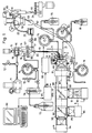
- figure 1 illustrates a schematical view of a measuring system according to the invention.
- the fluid medium in which particles are suspended is transferred from a sample cup 24, which is illustrated in the central, right-hand part of Fig. 1, to a sample reservoir 14 shown in the central upper part of Fig. 1 and further to a measuring cuvette, which is composed of two parts 3 and 4.
- the specimen is drawn from the two-part measuring cuvette 3, 4 by means of a drainage pump 80 shown in the lower right-hand part of Fig. 1.
- an electrical measurement of the specimen is performed by means of electrical circuitry comprised in a measuring block 86.
- the specimen is also subjected to an optical measurement, as a lamp 90, shown in the lower part of Fig.
- the measuring circuit 1 emits light to the cuvette through a mirror 97 and through an objective 65, which light is partly reflected from the cuvette.
- the light reflected from or emitted from the cuvette is detected by means of photodetectors 94 and 96.
- the measuring signals generated by the photodetectors 94 and 96 and by the block 86 are supplied to a computer 88, which optionally controls the operation of the system and generates indications of the operation of the measuring system.
- the individual components together constituting the measuring system is to be described in greater details below.
- Fig. 2 is a perspective view illustrating the central parts of the cuvette.
- a facial surface 10 of a plate 3 constituting one of the two parts or body halves of the cuvette is disclosed.
- the plate 3 may be made from quartz glass.
- a channel-shaped groove 1 is provided, which may e.g. be formed by a cutting or milling operation, e.g. by means of a cutting tool or the like.
- the groove 1 constitutes a section of a rectilinear cylinder having a circular cross section of a radius of curvature of approximately 50 »m, a depth from the facial surface 10 less than approximately 40 »m, such as 30-35 »m, and a width at the facial surface 10 of approximately 100 »m.
- This configuration has been found suitable for measuring particles having overall diameters of approximately 8-15 »m or less.
- the continous bore 8 shown in the upper part of Fig. 2 constitutes a feeding passage for the feeding or supply of a diluent
- the continous bore 7 constitutes a feeding passage for the feeding or supply of the specimen to be analyzed
- the continous bore 9 shown in the lower part of Fig. 2 constitutes a drainage passage. All three passages may be of cross-sectional dimensions of e.g. approximately 1 mm.
- the electrodes constitute two cylindrical rods which have been pressfitted or cast into through-going bores.
- the electrodes 5 and 6 may e.g.
- the groove 1 extends through the electrodes 5 and 6.
- the groove 1 is preferably cut or milled after the rods 5 and 6 are pressfitted into the through-going bore or after the rods 5 and 6 are solidified, and after the facial surface 10 has been subjected to a face grinding.
- the continous bores 7 and 8 may suitably be machined before the face grinding of the facial surface 10.
- FIG 3 discloses the two-part cuvette 3, 4 in greater details.
- the plate 3 is received in and fixed to a movable collar 26, which is movable or displaceable relative to a stationary collar 27.
- An 0-ring 28 is arranged circumferentially encircling the movable collar 26.
- a planar plate 4 of a transparent material such as quartz glass is arranged adjacent to the exposed, facial surface 10 of the plate 3.
- the plate 4 is preferably face ground and has parallel outer surfaces, one of which is designated the reference numeral 25 and faces the facial surface 10 of the plate 3.
- the other outer surface of the plate 4 is arranged adjacent to and in contact with an outer plane surface of an objective lens 65.
- the plate 4 and the objective lens 65 together constitutes an integral assembly.
- the assembly constituted by the plate 4 and the objective lens 65 is arranged in an lens holder 61, the front part of which is shown in Fig. 3.
- the lens holder 61 is received in a protecting collar 31 by means of an annular slip gasket 32, which protecting collar 31 is firmly and closely fitted to the stationary collar 27.
- Fig. 3 the lens holder 61 is shown in a position in which it is somewhat retracted from the plate 3, as is the case during a normal cleaning operating procedure, in which the cuvette parts are cleaned.
- fittings 34 are shown, which fittings are arranged in each of the three bores 7, 8 and 9 and received in the plate 3 so as to connect the bores with tubes or tubings for feeding or disharging liquid as it will be explained in greater details below.
- a single tube or tubing 13 is shown, viz. the tube or tubing constituting a feeding passage for supplying the specimen to the bore 7.
- the opposite end of the tube or tubing 13 is connected to an outlet socket 20 of the above-mentioned sample reservoir 14.
- inlet socket 17 In the lower right-hand part of the sample reservoir 14 an inlet socket 17 is provided. In the central left-hand part and the upper left-hand part of the sample reservoir 14, two inlet sockets 18 and 19, respectively, are provided for supplying a rinsing liquid and pressurized air, respectively, to the sample reservoir 14 and to the measuring system, as will be explained in greater details below.
- the sample reservoir 14 further comprises a agitating system in order to ensure that particles suspended in the fluid medium are transferred from the sample reservoir 14 through the passage 13 in a homogenous suspension and furthermore in order to avoid that the particles stick to one another or block the passage 13.
- the agitating system comprises a motor-driven agitating magnet 15, which is arranged above the uppermost part of the sample reservoir 14, which magnet 15 is rotating around a basically vertical axis and influences an armature head 16 arranged within the sample reservoir 14 below the agitating magnet 15.
- An agitating wire 11 is connected to the armature head 16 and extends from the armature head 16 through the sample reservoir 14, through the outlet socket 20, through the passage 13 and through the passage 7 of the plate 3.
- the outer end 12 of the agitating wire projects from the passage 7 and into a passage 2 (shown in Fig. 8) and preferably contacts the surface of the passage 2, which surface is located opposite to the passage 7 and is constituted by part of the facial surface 25 of the plate 4.
- the upper section of the agitating wire which section extends through the sample reservoir 14 simulataneously agitates the fluid medium in which particles are suspended in the reservoir 14 so as to avoid any sedimentation of particles in the sample reservoir 14.
- a cross-sectional view of the passage 13 is shown, in which the agitating wire 11 is received, illustrating that the agitating wire has a generally square cross section.
- the agitating wire 11 preferably has an outer lateral dimension of approximately 0.2-0.5 mm, and particularly an outer lateral dimension of approximately 0.3 mm.
- the wire 11 may be made from nylon, polypropylene, polycarbonate, Teflon or of a similar material, which, on the one hand, does not swell in water, is compatible to the fluid medium or liquid to which it is exposed and is resilient and flexible, and which, on the other hand, is so strong that it does not twist during the agitating movement or relation.
- the wire has a circular cross section (not shown) instead of a polygonal cross section and has a diameter of approximately 0.2-0.5 mm, preferably of approximately 0.3 mm.
- a wire having a circular cross-section has been found to produce less acustic and electric noise, and is consequently preferable for particularly critical measurements.
- the lens holder 61 of the two-part cuvette is shown in Fig. 3 in a position in which the cuvette is cleaned, and in which a cleaning brush 51 in a manner to be explained in greater details below is moved downwardly, while rotating, across adjacent facial surfaces of the plates 3 and 4 and also cleans the outer, exposed surfaces of the groove 1 of the electrodes 5 and 6.
- a cleaning brush 51 in a manner to be explained in greater details below is moved downwardly, while rotating, across adjacent facial surfaces of the plates 3 and 4 and also cleans the outer, exposed surfaces of the groove 1 of the electrodes 5 and 6.
- a spring 37 which is supported by a spring bracket, which is further supported and mounted on a metering screw 38, as will be explained in greater details below, excerts a force through a central supporting sphere 36 and a central pin 30 of the movable collar 26, in which the plate 3 is received and causes that the movable collar 26 is positioned in contact with a number of positioning spheres 29 which are received in corresponding bores of the stationary collar 27.
- the positioning spheres 29 ensure that the movable collar 26 is placed in a precise and well-defined position by means of the spring loading.
- a total of three spheres 29 are arranged at a mutually angular spacing of 120° at the outer periphery of the movable collar 26 and fastened to the stationary collar 27 as shown in Figs. 3 and 5.
- the lens holder 61 is moved forwardly, i.e. to the right as shown in Figs. 3 and 5, and to the position shown in Fig. 5.
- the facial surface 25 of the plate 4 which constitutes the left-hand cuvette body member or part, abuts the facial surface 10 of the plate 3, which constitutes the right-hand cuvette body member or part and presses the right-hand cuvette body member or plate 3 and the movable collar 26 somewhat to the right as shown in Fig. 5 against the spring force of the spring 37, by which movement the positioning spheres 29 are unloaded.
- the cuvette assembly makes it possible to compensate for small variations or angular inaccuracies and to obtain a perfect, closely fitted facial contact between the facial surfaces 10 and 25 of the two plates 3 and 4, respectively, which together constitute the cuvette.
- the agitating wire 11 is preferably adapted to project from the passage or bore 7, when the cuvette is being opened, e.g. by 1-3 mm, and to pull back the outer end 12 in the direction towards the passage or bore by contacting the facial surface 25 of the opposite cuvette body member or plate 4, when the cuvette assembly is being closed.
- Fig. 6 illustrates mechanical details of the cuvette structure or assembly.
- a stationary, box-shaped cuvette bracket 33 is shown, in which the stationary collar 27 is arranged.
- the plate 3 is shown, which is received in and fixed to the movable collar 26.
- the displaceable or movable parts are shown in their completely retracted positions so as to disclose two of the positioning spheres 29.
- the spring bracket 39 is illustrated, which as indicated above constitutes the fixed contact surface of the spring 37, and the metering screw 38 for adjusting the spring tension and consequently the force generated by the spring 37. In its operating position, the spring bracket 39 is fixed relative to the cuvette bracket 33, e.g. by means of screws or any other suitable means.
- a section of the optical system comprising particularly the lens holder 61, which supports the plate 4 and the objective lens 65 (indicated by a dotted line in Fig. 6) is shown.
- the lense holder 61 is received in and fixed to a bracket 60, which is journalled on guiding tracks 63 and is displaceable or movable in a direction parallel to an optical axis 67 of the optical measuring system relative to the stationary bracket 62 by means of a motor 64, by means of which the plate 4 is displaced or moved in directions towards and from the adjacent plate 3, as explained above with reference to Figs. 3 and 5.
- Fig. 6 further illustrates the cleaning brush 51, which is caused to rotate by means of a brush actuator 52 and which is supported by a brush-actuator supporting bracket 53.
- the bracket 53 is journalled on guide tracks 54 and is displaceable upwardly and downwardly in a direction substantially parallel with the facial surfaces 10 and 25 of the plates 3 and 4, respectively, by means of a displacement actuator 55.
- the facial surfaces 10 and 25 of the cuvette body members or plates 3 and 4, respectively are cleaned in the position in which the cuvette body members or plates 3 and 4 are separated from one another (cf. Fig. 3) by means of the cleaning brush 51 rotatating and simultaneously moving fairly slowly downwardly between the facial surfaces of the plates 3 and 4 and up again.
- a rinsing liquid is injected towards the facial surfaces of the plates 3 and 4, which rinsing liquid is discharged in the cleaning operation as will be discussed below.
- Fig. 7 shows a hose pump 41 of a type which may be utilized in the measuring system according to the invention.
- the hose pump 41 comprises, as shown in Fig. 7, a motor 43, which causes a rotor 44 to rotate relative to a rotational axis 45.
- the rotor 44 is provided with pressure rollers 46, the axes of which extend radially from the rotor.
- a stationary component of the hose pump 41 is shown below the rotor 44, which component comprises a generally cylindrical body 40 having a radially projecting, disc-shaped abutment collar 48 which supports a tube 42 which extends through holes 47 in the abutment collar 48 and which is tightened around a groove 49 arranged in the peripheral upper surface of the cylindrical body 40.
- the movement of the tube 42 is limited downwardly in the longitudinal direction of the rotor axis by the abutment collar 48 and upwardly in the longitudinal direction of the rotor axis by a tube-retaining edge 50.
- the tube 42 is tightly mounted so as to be stretched along the entire circumference by tensile stress.
- the tube may be retained by tensile stress only by means of the friction of the holes 47, provided that a tube of a suitable dimension and resilience is utilized, and provided that the holes 47 are adapted to this dimension and resilience.
- the pressure rollers 46 influences the tube axially so as to flatten the internal aperture of the tube completely at a section below each roller, so as to produce a peristaltic pumping action when the rotor 44 rotates. Due to the tensile stress of the tube, the tube is influenced by the force of friction between the tube-retaining edge 50 and the abutment collar 48 across the entire circumference so that it is completely stable.
- a more continuous and well-defined pumping action and a more continuous pumping process are achieved as compared to the pumping action and the pumping process which is obtainable by means of the hose pumps well-known within the art, in which pumps the tubes normally tend to move relative to the groove when inflated.
- the hose pump comprises a total of four pressure rollers, which are arranged at an angular spacing of 90°.
- This hose pump ensures a continous and well-controlled pumping, however, a discontinuity cannot be totally avoided whenever a roller rolls accross the section of the discharge holes 47, and consequently the tube bends.
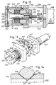
- a pressure roller leaves one end of the tube and hits the opposite end, a step-wise variation of the tube pressure is unavoidable. If the flow rate preferably is to be completely steady, this may be achieved by measuring only during the time intervals between the passage of the pressure rollers across the tube bends, i.e. in four periods per turn of the rotor 44 shown in Fig. 7. However, these time intervals are fairly short, but this situation may be improved by means of a special hose pump, which is shown in Fig. 10.
- This hose pump which is designated the reference numeral 35 in its entity, differs from the hose pump shown in Fig. 7 in that only two pressure rollers are provided having axes arranged 60°-90° spaced apart.
- a suitable time of measuring is achieved with a completely continuous liquid flow during one rotation of the rotor 44 at approximately 240°-270°, viz. 270°-300° minus the period, which is required for the pressure roller to move across the tube bends at the discharge holes 47.
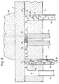
- Fig. 8 is a schematical and sectional view of the cuvette assembly.
- the plane extends longitudinally through the center of the groove, which defines the capillary passage 2 together with the facial surface 26 of the plate 4 perpendicularly to the facial surfaces 10 and 25 of the plates 3 and 4, respectively.
- Fig. 8 basically serves the purpose of illustrating the movement of the particles through a measuring zone.
- the plate 3, which constitutes a first cuvette body half, in which the groove 1 is machined, is shown in the lower part of Fig. 8, and the plate 4, which constitutes a second cuvette body half, is shown in the upper part of Fig. 8.
- the objective lens 65 is arranged in contact with the plate 4 as discussed above.
- the optical axis 67 is also shown.
- light is emitted through the objective lens 65 along the optical axis 67, by which emission a section of the passage 2 encircling the optical axis 67 is illuminated.
- the light which is detected by the photodetectors 94 and 96 is reflected light which is reflected along the optical axis 67.
- the bore or passage 8 for feeding the diluents the bore or passage 7 for feeding the specimen, the first electrode body 5, the second electrode body 6, and the bore or passage 9 constituting a drainage passage are shown.
- the fittings 34 are received in the respective bores or passages so as to enable that the above-mentioned tubes or tubings may be connected to these fittings 34.
- a section of the agitating wire 11 is shown in the bore or passage 7, the outer end 12 of which agitating wire extends to and contacts the facial surface 25 of the plate 4 as discussed above.
- the wire being a wire of polygonal cross section, is twisted during the agitation movement.
- the bores 7, 8 and 9 preferably have diametres of the order of 1 mm, whereas the depth of the groove 1 and consequently of the capillary passage preferably is of the order of 30-35 »m, by which it is to be understood that there exists a risk of blocking the capillary passage. Blocking of the capillary passage may particularly occur at sections where the particles are to pass into the capillary passage 2, and accordingly is is essential that the agitating wire 11 influences the section of the passage 2 at the bore 7, i.e. at the section in which the particles of the specimen are introduced into the capillary passage.
- the diluent may be added through the bore or passage 8 at the upstream end of the capillary passage 2 and may be mixed with the specimen downstream along the capillary passage 2.
- a plurality of arrows, one of which is designated the reference numeral 68, indicates the flow path through the bores 7 and 8, through the capillalry passage 2 and through the bore 9.
- the reference numeral 66 indicates particles suspended in the liquid, which is introduced into the capillary passage 2 through the bore 7.
- the flow of liquid and particles suspended therein are subjected to an electrical field, which is generated between the electrodes 5 and 6, as indicated by lines of flux 69, which extend along the passage 2 with the exception of two end sections adjacent to the electrodes 5 and 6, in which end sections the lines of flux bend towards the surfaces of the electrodes 5 and 6.
- the electrodes are utilized to measure the conductivity of the liquid by a method well-known in the art, e.g. by supplying a contant voltage or a constant current to the electrodes and by measuring the electrical current.
- a measuring result is obtained, which is indicative of and is proportional to the volume of the particles, when within the electrical field.
- the measurement implies the generation of exactly the same electical field onto each particle and onto all parts of a particle, and it is therefore to be expected that a not entirely homogeous field will cause an inaccurate measurement, since the particles which pass in the upper section of the capillary passage are exposed to a lower electrical field strength or stay in the electical field for a shorter period of time than the particles which pass in the lower section of the passage.
- it has surprisingly been found that extremely reliable, reproducible and accurate electrically measuring results are achievable by the above-described embodiment of the electrodes, which measuring results are not substantially influenced by edge effects or inhomogenities of the electrical field.
- the field extending in a manner so as to be basically homogenous at the section between the electrodes as the lines of flux are directed parallel to the direction of flow of the particles.
- the shortest distance between the electrodes is 0.08 mm
- the depth of the capillary passage 2 is 30-35 »m as explained above. Therefore, it is obvious that the results of the electrical measuring correspond to the particles passing a homogenous field, which has a length of approximately 0.12-0.35 mm.
- Another essential point is that the particles, since the flow of liquid exhibit a laminar flow behaviour, tend to be centered towards the centre of the capillary passage, in which the velocity of the flow of liquid is highest. Consequently, the particles tend to follow at exactly the same path.
- a determination of the particle volume by measuring the conductivity of the particle is, of course, only possible provided only a single particle is exposed to the electrical field at a time. In real life, the distances between the particles will be statistically varying, and accordingly particle coincidence cannot be completely avoided.
- the frequence of particle coincidence may, however, be reduced to an acceptable level such as approximately 2% by diluting the specimen, so that the average distance between the particles may be e.g. 2.5 mm.
- the number of measured particles will in real life be smaller. If e.g. only every tenth particle has a volume within the relevant interval of volumes, an analysis of 5000 particles may be carried out in approximately 2 minuttes, and within this period of time 50.000 particles have passed the capillary passage 2. If two particles succeed one another in immediate succession, this may be detected by means of the electical signal exhibiting a step-wise alteration each time a particle enters of leaves the electrical field. Consequently, it is possible electronically to accept measuring signals which correspond to the passage of a single particle through the field, whereas all other measuring signals are suppressed.
- the particle When a particle has passed the electrical field, the particle moves further along the capillary passage 2 as indicated by the arrow 68 and passes the optical axis 67 as indicated in Fig. 8.
- the particle is illuminated by means of rays of light, and the light which is reflected along the the optical axis 67 is detected by the photodetectors 94 and 96 of the measuring system, and electrical signals generated by the photodetectors 94 and 96 are analyzed in order to determine if the particles fluorescence.
- the colour of fluorescence may also be determined, e.g. by means of an optical system which measures the intensity of light within two or more specific spectral bands. This arrangement serves the purpose of determinating or classifying the particles. From the combined electrical and optical measurements, in combination with information regarding the volume of liquid, the concentration of relevant fluorescent particles suspended in the liquid is derived.
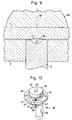
- the exposed outer surface of the electrode 6 acts as a light reflector, and as evident from the cross-sectional view of figure 9, the surface design causes a concentrating reflector effect so that the light converges, by which means a high intensity of light is achieved in the measuring area.
- the facial surface 10 of the plate 3 surrounding the light-reflecting electrode 6 does not fulfil any reflecting function and is preferably adapted to absorbe light.
- the passage 2 may have a radius of curvature of 50 »m and a depth of 30-35 »m, whereas the width of the passage may be of approximately 100 »m, which is suitable for analyzing particles having diameters of the order of 8-15 »m or less, as explained above.
- the illuminating system comprises a flash lamp, e.g. of the xenon type, which is ignited after a predetermined delay, when a particle of a suitable size has been detected in accordance with the conductivity measurement. Since the flow rate of the fluid medium in which the particles are suspended is well-known, it is possible to adapt the delay in a manner that the flash light illuminates the particle exactly when it reaches the optical axis 67.
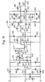
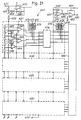
- the electrical circuit comprised in the block 86 shown in Fig. 1 and to be described below with reference to Figs. 16-21 is adapted to activate the flash lamp for emitting as many as 100 synchronized light flashes per second. Furthermore, by employing a periodically ignited or activated flash lamp, heating of the specimen is reduced as compared to a constant illumination of the measuring zone.
- a specimen is extracted from the sample cup 24, which contains a fluid medium or a liquid in which particles to be analyzed are suspended.
- a suction device comprising a lifting device 70 and a submersible suction tube 83, which is submerged into the sample cup 24, the submersible suction tube 83 is connected directly to a suction duct 23, through which the specimen is passed to a particle filter 22, which serves the purpose of retaining particles having volumes bigger than a predetermined volume or diameter, e.g. particles of diameters larger than 20 » whereupon the specimen is passed through an inlet valve 89 to the inlet socket 17 of the sample reservoir 14.
- a light source 56 e.g. a light emitting diode or LED, is arranged, which light source 56 emits light which is passed through the sample reservoir 14, which is made from light-transparent material or which comprises a wall section of a light-transparent material, adjacent to which wall section the light source 56 is arranged, towards a photodetector 57, by means of which photodetector 57 the supply of the fluid medium or the liquid from the cup 24 to the sample reservoir 14 is controlled, as the supply of the liquid from the cup 24 to the sample reservoir 14 is interrupted as the liquid level of the sample reservoir 14 exceeds the liquid level defined by the optical light path from the light source 56 to the light photodetector 57.
- a light source 56 e.g. a light emitting diode or LED
- the socket 18 of the sample reservoir 14 is connected to a flush pump 74, e.g. a hose pump of the type described above with reference to Fig. 7.
- the inlet of the flush pump 74 communicates with a valve-controlled vent 72 and with a tank 73 containing a rinsing or cleaning fluid through a heated liquid container 79, from which pre-heated rinsing or cleaning fluid is supplied to the socket 18 of the sample reservoir 14 through a valve-controlled conduct or tube.
- the flush pump 74 is a reversible pump and is applied when absorbing liquid from the cup 24, during which operation the valve-controlled conduct or tube establishing communication between the heated liquid container 79 and the socket 18 is closed and during which operation the valve-controlled vent 72 is open.
- the flush pump 74 is stopped, the inlet valve 89 is closed, and the valve-controlled vent 72 is also closed or blocked.
- the socket 19 of the sample reservoir 14 is connected to a source of pressurized air or a compressor 71 and to a valve-controlled vent 72′.
- the transfer of the specimen from the sample reservoir 14 to the two-part cuvette 3,4 is accomplished in the following three-step procedure. Firstly, the air compressor 71 is activated for generating pressurized air, e.g. of approximately 1 bar above the atmospheric pressure. While the air compressor 71 is activated for generating pressurized air, the valve-controlled vent 72′ is closed so as to supply the pressurized air generated by the air compressor 71 to the sample reservoir 14.
- the two-part cuvette 3, 4 is open for a short period of time of the order of 20 ms as the lens roller 61 supporting the plate 4 is moved away from the plate 3, as explained above with reference to Figs. 3 and 4, by which opening the specimen is forced through the feeding passage 13 so as to discharge or vent air trapped within the passage 13 to the atmosphere.
- the two-part cuvette 3, 4 is closed after the above-described opening of the cuvette for venting air trapped within the passage 13 and filling the passage 13 with the specimen from the sample reservoir 14, the specimen contained within the sample reservoir is drawn or sucked into the capillary passage 2 shown in Fig.
- the drainage pump 80 which is implemented as a hose pump of the type described above with reference to Fig. 10, is operated at a well-defined velocity and accordingly controls the flow rate of the liquid through the capillary passage 2 shown in Fig. 8 of the two-part cuvette 3, 4.
- the drainage pump 80 is further connected to a waste container 81.
- the bore or passage 8 of the measuring cuvette 3, 4 communicates with a tank 75 containing a diluent, which may be propelled by means of a pump 76, which is also implemented as a hose pump of the type described above with reference to Fig. 10.
- the specimen is supplied to the passage 2 of the measuring cuvette 3, 4 from the sample reservoir 14 through the passage 13 interconnecting the outlet socket 20 of the sample reservoir 14 and the bore or passage 7 of the measuring cuvette 3, 4 propelled by the pressurized air, which is supplied to the sample reservoir 14 from the pressurized air source or compressor 71.
- the flow of liquid through the passage 2 of the cuvette 3, 4 is controlled by the drainage pump 80, which is operated at a constant rotational speed for generating a contant flow rate through the passage 2 of the measuring cuvette 3, 4.
- the pump 76 may be activated for supplying the diluent from the tank 75 to the passage 2 of the measuring cuvette 3, 4 in order to alter the dilution ratio of the specimen which is transferred through the passage 2 of the measuring cuvette 3, 4.
- the pump 76 may be operated at a variable rotational speed, be accelerated or decelerated or stopped during the measuring phase in order to generate a fairly constant dilution ratio of the specimen which is transferred through the passage 2, or at least in order to provide an adequate dilution ratio for ensuring that the particles of the specimen are transferred through the passage 2 individually and sequentially in order to render it possible to subject the particles individually to the electrical field generated by the electrodes 5 and 6 within the passage 2 and to expose the particles individually to the light flash, still ensuring a constant flow rate through the passage 2, which constant flow rate is of the utmost importance in order to guarantee that the particles that are transferred through the passage 2 are shifted from exposure to the electrical field to exposure to the light flash within a predetermined and fixed period of time.
- the blocking is easily eliminated by carrying out the above-described second step of the feeding procedure, i.e. by opening the two-part cuvette 3, 4 for a short period of time, e.g. of the order of 20 ms, by which opening the blocking is eliminated, as the particles blocking the capillary passage 2 or the feeding passage 3 are expelled from the two-part cuvette 3, 4, which is open, or from the feeding passage 13 into the opened two-part cuvette 3, 4.
- the lifting device 70 comprises a cam follower 85, which cooperates with a cam 84, serving the purpose of causing the submersible tube 83, when raised from the sample cup 24, to swing to a position in which the submersible tube 84 points to a spillage collector 82, which communicates with a spillage conduit 77.
- the inlet valve 89 is opened, and the pressurized air supplied to the sample reservoir 14 causes the conduit 23 and the submersible tube 83 to be dry blasted, as a possible residue of the specimen contained in the sample reservoir 14 is flushed from the sample reservoir 14 and expelled from the submersible tube 83 to the spillage collector 82.
- the valve of the conduit interconnecting the heating container 79 and the flush pump 74 is opened and the flush pump 74 is activated so as to absorb pre-heated rinsing liquid from the heating container 79, in which the rinsing liquid is heated in order to increase the cleaning effect of the rinsing liquid.
- the rinsing liquid is transferred to the sample reservoir 14 and expelled through the particle filter 22, the conduit 23 and the submersible tube 83 to the spillage collector 82.
- the flush pump 74 is stopped, and the compressor 71 is activated briefly so as to dry blast the absorption conduit 23 and the submersible tube 83.
- the inlet valve 89 is reclosed, and the measuring cuvette 3, 4 is opened as the lens holder 61 supporting the plate 4 is moved to the left.
- the flush pump 74 is reactivated transferring rinsing liquid to the sample reservoir 14 and expelling the rinsing liquid through the feeding passage 13 into the opened measuring cuvette 3, 4, from which the rinsing liquid is drained through the spillage passage 77.
- the drainage pump 80 is activated for absorbing liquid from the drainage tank 81 so as to discharge the liquid from the drainage tank through the bore or passage 9 to the opened measuring cuvette 3, 4.
- the cleaning brush 51 is then activated and moves, when rotating, across the facial surfaces 10 and 25 of the plates 3 and 4, respectively, in a manner that the facial surfaces 10 and 26 and the groove 2 including the exposed surfaces of the electrodes 5 and 6 are washed by means of the liquids furnished and subsequently broomed by means of the brush 51.
- Spillage fluid is discharged through the spillage passage 77 and is pumped away by means of a spillage pump 78, which is operated continuously during the washing or rinsing operation.
- the quantity of liquid that is transferred through the measuring cuvette 3, 4 when measuring is very small, and preferably so small that it does not fill up the drainage passage 21, nor is mixed with the clean rinsing liquid, which is filled into the drainage tank 81 in advance.
- a waste reservoir may be provided in the conduct or tube interconnecting the bore or passage 9 and the drainage pump 80.
- the flush pump 74 and the drainage pump 80 are stopped, and the source of pressurized air or the compressor 71 is briefly activated so as to dry blast the sample reservoir 14 and the feeding passage 13, after which operation the cuvette is reclosed so as to be ready for a subsequent measuring operation.
- Fig. 1 further illustrates the optical system, which in addition to the components described above with reference to Fig. 6 comprises a stationary housing component 98, in which the light source 90 and the detectors 94 and 96 are arranged.
- a light source or a xenon flash lamp 90 emits light that passes through an aperture 91, through a colour filter 99 and is directed to a dichroic mirror 97, which projects the light in a direction along the optical axis 67 longitudinally through the housing component 89 towards the objective lens 65 through a suitable optical system comprising focusing lenses and collimators per-se well-known to a person having ordinary skill in the art.
- the light which is reflected from the cuvette in a direction along the optical axis 67 passes through the objective lens 65.
- a predetermined spectral range of the reflected light passes through the dichroic mirror 97 and is further transmitted along the optical axis 67 to a second mirror or a so-called beam splitter 92, which mirror allows a first part of the reflected light to pass straight through the second mirror or beam splitter 92, and which second mirror or beam splitter 92 deflects a second part of the reflected light.
- the first part of the reflected light i.e. the light passing straight through the beam splitter 92, is directed to a first colour filter 93 and a first photodetector 94 arranged along the optical axis 67.
- the second part of the reflected light i.e. the light deflected by the beam splitter 92 is directed substantially perpendicular to the optical axis 67 to a second colour filter 95 and a second photodetector 96.
- the dichroic mirror 97, the beam splitter 92 and the colour filters 93 and 95 are so-called interference filters, which are adapted to allow the relevant flourescence colours to be reflected, beamsplitted or transmitted, whereas wavelength range of light different from the relevant wavelengths or wavelength ranges are substantially blocked.
- the optical system is per-se well-known to a person having ordinary skill in the art and needs therefore not to be described in greater details.
- the colour filter 99 and the xenon flash lamp 90 are adapted to illuminate the measuring cuvette 3, 4 by light within the spectral range of 475-495 nm, whereas the colour filters 93 and 95 and the beam splitter 92 are adapted so that the first photodetector may register light of the spectral range of 575-640 nm and the second photodetector light of the spectral range of 520-560 nm.
- a iodine quartz photoflood lamp of 100 W is used instead of the xenon flash lamp together with the same arrangement of colour filters.
- an Argon laser is used for illumination, which laser emits light of a wavelength of 480 nm.
- the measuring block 86 shown in Fig. 1 is connected to the first and the second electrodes 5 and 6, repectively, and is adapted to supply an electrical signal such as an AC or DC voltage or current signal or a combination thereof to the electrodes, e.g. an AC voltage of 9 V and of a frequency of 50-100 kHz, such as 80-90 kHz.
- the measuring block 86 also includes circuitry for performing the electrical measurement described above, e.g. for determining impedance variations such as by impedances of the order of 10 k ⁇ - 50 k ⁇ to measure variations of the impedance as small as 10 ⁇ 5.
- the command block 87 shown in Fig. 1 receives the electrical signals generated by the various electrical units of the measuring system, among others the optical system, the measuring block 86, the photodetectors 94 and 96 etc., and generates control signals for controlling the operation of the various components of the measuring system such as the valves, the pumps, the actuators etc., which components all are adapted to be remotely controlled.
- the command block 87 further constitutes an interface block to the computer 88.
- FIG. 11 is a schematical view of an alternative embodiment of the fluid-transfer system of the measuring system disclosed in Fig. 1, in which an alternative embodiment of the liquid-transfer system and an alternative and presently preferred embodiment of a pump for transferring fluid or liquid are employed, which pump is a piston-type pump.
- a first piston pump 176 and a second piston pump 180 are employed substituting the hose pumps 76 and 80, respectively, shown in Fig. 1.
- the containers 75 and 81 shown in Fig. 1 are in Fig. 11 substituted by pressurizable containers 175 and 181, respectively.
- the pressurized air conduit interconnecting the source of pressurized air or the compressor 71 and the inlet 19 of the storage container 14 shown in Fig. 1 is provided with a T-shaped connector for supplying pressurized air to the pressurizable containers 175 and 181.
- the pressurized air conduit supplying pressurized air from the compressor 71 to the containers 175 and 181 is provided with controllable valves for controlling the supply of pressurized air to the containers 175 and 181.
- the pressurized air conduit connected to the container 175 is provided with a controllable valve 177
- the pressurized air conduit supplying pressurized air to the container 181 is provided with a controllable valve 178.
- the conduit interconnecting the piston-type pumps 176 and 180 and the containers 175 and 181, respectively, are also provided with controllable valves designated the reference numerals 179 and 182, respectively.
- the provision of the pressurizable containers 175 and 181 basically serves the purpose of rendering it possible to vent the piston pumps 176 and 180, respectively, by forcing the liquids contained withing the containers 175 and 181, respectively, into the piston pumps 176 and 180, respectively.
- the piston-type pumps 176 and 180 are, however, extremely advantageous as compared to the hose pumps discussed above with reference to Figs. 1, 7 and 10 in that the piston-type pumps 176 and 180 render it possible to provide an accurate and easily controllable dosage of liquid and consequently an extremely accurate and easily controllable liquid transfer.
- the piston-type pump which is preferably employed in the measuring system according to the present invention as discussed above with reference to Fig. 11, is shown in an elevational, sectional view and in a perspective view, respectively.
- the piston-type pump is designated the reference numeral 141 in its entity.
- the piston-type pump 141 comprises two stationary blocks 142 and 143, which are kept in parallel and spaced apart relationship by means of distance rods 144 and 145.
- a drive motor 146 is fixed to the stationary block 143 by means of screws, threads or alternative, appropriate fixation means and has an output shaft 147, which extends from the drive motor 146 through a through-going bore of the stationary block 143 into the space defined between the stationary blocks 142 and 143.
- a piston housing is fixed to the block 142.
- the piston housing is composed of basically three components, an inner housing component 148, an outer housing component 149 and an end plate 150.
- the end plate 150 is fixed to the stationary block 142 by means of a total of four screws 151, which extend through through-going bores of the outer housing component 149 for assembling or bolting the end plate 150 and the outer housing component 149 to the stationary block 142.
- the inner housing component 148 is received within the outer housing component 149 and extends through a through-going, stepped bore of the stationary block 142.
- a sealing O-ring 152 is received within a circumferential recess of the outer housing component 149 and serves the purpose of providing a fluid-tight connection between the outer housing component 149 and the end plate 150.
- a frustoconical space is defined, which frustoconical space 153 communicates with two tubes 154 and 155, which extend through through-going bores of the outer housing component 149 and through the end plate 150, respectively.
- the tubes 154 and 155 are in mutual fluid communication through the frustoconical space 153.
- a total of five annular sealing gaskets 156 are in a kept and spaced apart relationship by means of four annular spacers 157 and are received and kept together as a sealing gasket assembly between the inner housing component 148 in the outer housing component 149.
- a cylindrical passage extends, in which a piston body 158 is movable to and from the end plate 150 for filling out a smaller or larger fraction of the frustoconical space 153.
- the annular sealing gaskets 156 provide a fluid-tight guidance of the piston body 158 and prevent any leakage of fluid or liquid from the frustoconical space 153.
- a bushing or socket 159 extends into the inner space defined between the stationary blocks 142 and 143 and is fixed to a collar 160.
- the bushing or socket 159 is provided with an internal thread 161, which measures with an outer thread 162 of a threaded shaft 163, which is fixed to the output shaft 147 of the drive motor 146 by means of a clutch 164.
- a highly accurate and easily controllable dosage of fluid may be transferred to or from the piston-type pump 141 through one of the tubes 154 and 155 by moving the piston body 158 away from the adjacent inner surface of the end plate 150 or towards said inner surface by rotating the output shaft 147 of the drive motor 146 in a first rotational direction or in the opposite rotational direction for causing the bushing or socket 159, which is provided with the internal thread 161 meshing with the outer thread 152 of the threaded shaft 153 to move relative to the rotating threaded shaft 153.
- the collar 160 may be provided with an outwardly or upwardly protruding rod 165, which serves the purpose of activating a first or a second microswitch 166 and 167, respectively, which serve the purpose of detecting preset end positions of the collar 160 and consequently preset end positions of the piston body 158 within the frustoconical space 153 and consequently deactivate the drive motor 145 in case the piston body 158 is about to be moved into intimate contact with the inner surface of the end plate 150, which might mechanically harm the piston-type pump, or is about to be retracted to far from the inner sealing gaskets 176, which might cause leakage of fluid or liquid from the piston-type pump.
- a presently preferred method is shown of producing a lens assembly comprising an objective lens and a plate component together constituting a lens assembly serving the same purpose as the lens assembly described above with reference to Figs. 1, 3, 5, 6 and 8 and comprising the objective lens 65 and the plate 4.
- the production technique illustrated in Fig. 14 involves assembling the objective lens and the plate by means of non-light-transparent glue for, to any substantial extent, eliminating any light-scattering and light-diverging effects originating from the optical interface between the objective lens and the plate to which the objective lens is fixed.
- An objective lens 106 of the assembly shown in Fig. 14 differs from the objective lens 65 discussed above in that the objective lens is provided with an outer conical surface 107 opposite to an outer spherical, convex surface of the objective lens 106.
- the plate 104 and the objective lens 106 are preferably made from the same material, such as quartz glass, or are made from materials of substantially identical, optical properties.
- the objective lens 106 is glued to the plate 104 by means of a glue, which provides a light-intransparent layer 109, which bonds the outer conical surface 107 of the objective lens 106 to the conical recess 105 of the plate 104.
- the glue layer is solidified, a substantial fragment or section 110 of the plate 104 is removed in a grinding process, and a part of the objective lens 106 at the apex 111 of the pyramid defined by the conical surface 107 of the objective lens 106 is also removed. Consequently, a window or an aperture 112 is provided, which constitutes the window or aperture through which light is transmitted from the objective lens 106 to the adjacent passage 2, which is shown in Fig. 15, and furthermore, through which the light is transmitted from the passage, i.e. reflected light, through the objective lens 106.
- the lens assembly comprising the objective lens 106 and the plate 104 produced as discussed above with reference to Fig. 14 is shown arranged adjacent to the cooperating plate 3 of the two-part cuvette.
- the cuvette assembly shown in Fig. 15 further differs from the above-described two-part cuvette shown in Fig. 8 in that a total of three electrodes is provided, designated the reference numerals 115, 116 and 117.
- the electrode 117 primarily serves the purpose of defining a light-reflecting surface identical to the light-reflecting surface defined by the electrode 6 as discussed above with reference to Figs. 8 and 9.
- the provision of three or even more electrodes serves the purpose of rendering it possible to refine or elaborate the detection of the transfer of particles through the passage 2 from the inlet bore 7 to the outlet bore 9 by accurately detecting the presence of the particles within the passage 2 by means of two or more electrical fields so as to render it possible to accurately control that the light source is ignited for exposing a particle present within the passage 2 exactly at the time the particle is positioned adjacent to the mirror defined by the electrode 117 and adjacent to the window or aperture 112.
- the detection of the presence of a particle within the passage 2 may be established by the generation of an electrical field between the electrodes 115 and 116, and an additional electrical field may be generated between the electrodes 116 and 117 for controlling or surveying the transfer of the particle or particles through the passage 2 past the window or aperture 112 and past the exposed, mirror-defining end surface of the electrode 117.
- test bench setup comprises the above-mentioned computer 88 and a cabinet 88, in which four electronic apparatuses 189, 190, 191 and 192 are housed.
- the cabinet 188 and the electronic apparatuses 189-192 housed therein is connected to the computer 88 through a bus cable 193, which is provided with a plug 194, which is received in a mating and cooperating socket of the cabinet 189.
- the computer 88 basically comprises three sections, viz. a keyboard 195, a CPU (central processing unit) section 196 and a display or CRT (cathode ray tube) 197.
- the computer 88 is basically of the personal computer or PC-type.
- the electronic apparatus 189 constitutes an interface between the electronic, analogue and digital circuitries of the measuring system and the PC or computer 88.
- an interface to IBM PC/XT/AT PCs were established by means of a high-performance, high-speed, multi-function data acquisition card for IBM PC/XT/AT and compatible computers of the type PC-LabCardTM PC 812, which card was mounted within the CPU 196, and by means of a screw-terminal board of the type PC-LabCardTM PCL-780, which card was mounted within the housing 189.
- the electronic apparatuses housed within the housings 190, 191 and 192 constituted an AD converter (analogue-digital converter), a 24V/4A power supply and a level detector, respectively.
- the AD converter and the level detector 190 and 192, respectively, are to be described in greater details below.
- the 24V/4A power supply was a commercially available power supply unit.
- Fig. 17 a diagrammatic view of a presently preferred embodiment of an electronic circuitry of an electronic apparatus is shown, which electronic apparatus is connected to and communicates with the electrode bodies 5 and 6 shown in Figs. 3, 4 and 8.
- the diagrammatic view of Fig. 17 basically discloses nine sub-circuit sections housed within dotted-line boundary lines and designated the reference numerals 200-208, respectively.
- the sub-circuit section 200 constitutes an oscillator section including an electronic-oscillator circuit block 209, which is controlled by a crystal 210.
- the oscillator circuit block 209 generates an output oscillator signal, which is divided into an oscillator signal of a lower oscillator frequency by means of a total of four NAND gates 211-214.
- the output of the frequency-dividing circuit constituted by the NAND gates 211-214 is connected to an inverting input of an operational amplifier 215, the non-inverting input of which is grounded.
- the output of the operational amplifier 215 is connected to the inverting input thereof through a feedback resistor 216, which is shunted by a capacitor 217.
- the oscillator section 200 further includes two resistors 218 and 219 and two capacitors 220 and 221, which resistors 218 and 219 and which capacitors 220 and 221 are connected in a conventional configuration around the crystal 210.
- the oscillator 200 additionally includes the following peripheral components: An NPN transistor 222, resistors 223, 224, 225 and 226, and capacitors 227, 228, 229 and 230.
- the sub-circuit section 201 basically constitutes a current driver for supplying a constant-current oscillating signal to the electrodes 5 and 6 discussed above.
- the electrodes 5 and 6 are connected to the sub-circuit section 201 through terminals 232 and 233, which are connected to output terminals of a two-position, two-pole relay 234.
- the relay 234 is energized by means of a coil 235, which is connected to terminals 236 and 237. Provided the relay 234 is activated by energizing the coil 235, the terminals 232 and 232 and consequently the electrodes, such as the electrodes 5 and 6, alternatively the electrodes 116 and 117 shown in Fig.
- the input winding of the balancing transformer 238 is shunted by a capacitor 239 and is connected across the output and the inverting input of an operational amplifier 240, the non-inverting input of which is grounded.
- the inverting input of the operational amplifier 240 is connected to the output of the oscillator section 200, i.e. the output of the operational amplifier 215, through a series configuration of a resistor 241 and the above-mentioned capacitor 230. Consequently, the impedance across the electrodes, such as the electrodes 5 and 6, alternatively the electrodes 116 and 117 shown in Fig. 15, is connected in a balanced and symmetrical configuration, for providing a common-mode rejection of electrical noise from external sources, across the output and the inverting input of the operational amplifier 240, and consequently constitutes a feedback impedance or resistor.
- the inverting input of the operational amplifier 240 constitutes a virtual ground to which a current signal is supplied through the resistor 241, which converts the voltage signal supplied by the oscillator 200 into a current signal. Consequently, the operational amplifier 240 presents at its output a voltage signal, by means of which the operational amplifier drives a compensation current to its inverting input through the impedance connected across the output and the inverting input thereof for compensating the current signal supplied to the inverting input of the operational amplifier 240 through the resistor 241.
- the output signal generated by the operational amplifier 240 represents the impedance across the electrodes connected to the terminals 232 and 233.
- the section 201 further includes two resistors 242 and 243 and three capacitors 244, 245 and 246, which resistors 242 and 243 and which capacitors 244, 245 and 246 constitute low-pass filtering components connected to the NPN transistor 222 of the oscillator 200 for low-pass filtering an enable signal, which is supplied to the circuit 201, through a terminal 247.
- An additional terminal 248 is provided so as to render it possible to reset the oscillator circuit block 209 of the oscillator 200.
- the section 201 additionally includes two resistors 249a and 249b, which are connected across the output winding of the balancing transformer 238, provided the relay 234 is not activated.
- the section 202 basically constitutes a rectifier circuit block comprising two operational amplifiers 250 and 251, two rectifying diodes 252 and 253, a total of five resistors 254, 255, 256, 257 and 258, and further two capacitors 259 and 260.
- the rectifier 202 is of a conventional circuit configuration and is not to be described in greater details.
- the section 203 constitutes a low-pass filter implemented by means of an operational amplifier 260 constituting a second order, low-pass Bessel filter.
- the low-pass filter 203 further includes three resistors 261, 262 and 263 and four capacitors 264, 265, 266 and 267.
- the second order, low-pass Bessel filter of the section 203 is of a conventional circuit configuration and is not to be described in greater details.
- the sections 204 and 207 also constitute low-pass filter sections, which are identical to the low-pass filter of the section 203. Consequently, the sections 204 and 207 are not to be described in greater details.
- the section 205 constitutes a low-noise, 20dB Gain, inverting amplifier stage comprising an operational amplifier 270 and further an input capacitor 271, an input resistor 272, a feedback resistor 273, a feedback-resistor shunting capacitor 274, an output capacitor 275 and voltage-supply bypass capacitors 276 and 277.
- the section 206 constitutes a 20dB Gain, non-inverting amplifier stage comprising an operational amplifier 280, an input resistor 281, a feedback resistor 282, a feedback-resistor shunting capacitor 283 and a grounding resistor 284.
- the section 208 constitutes a 20dB Gain, inverting-amplifier stage comprising an operational amplifier 290, an input capacitor 291, an input resistor 292, a feedback resistor 293 and a feedback-resistor shunting capacitor 294.
- the output of the operational amplifier 290 is connected to an output terminal 295, at which a signal is generated representing the detection of the presence of a particle altering the electrical conductivity of the section of the capillary passage 2, shown in Fig. 8, adjacent to the electrodes 5 and 6, which section is exposed to the electrical field represented by the lines of flux 69, also shown in Fig. 8.
- the low-pass filter sections 203, 204 and 207 of the electronic circuit shown in Fig. 7 provide an electronic delay of the measuring signal generated by the electrodes connected to the terminals 232 and 233, which delay is of the order of approximately 150 »s and has to be taken into consideration in the overall measuring system setup as the delay constitutes a delay of the generation of a detection output signal at the output 295 of the operational amplifier 290 of the section 208 relative to the presence of the particle given origin to the generation of the detection signal at the electrode 5 shown in Fig. 8, during which delay the particle is transferred or shifted through the passage 2 towards the electrode 6, also shown in Fig. 8.
- FIG. 18 an electronic circuit is shown, which constitutes a level detection circuit, to which the output signal present at the output terminal 295 of the electronic circuit shown in Fig. 17 is input.
- the electronic circuit shown in Fig. 18 is designated the reference numeral 300 in its entity and receives the above-mentioned output signal at an input terminal 301.
- the input signal presented to the electronic circuit 300 at the input terminal 301 is presented to a second-order, low-pass filter comprising an operational amplifier 302, two input resistors 303 and 304 and two capacitors 305 and 306.
- the output of the second order, low-pass filter comprising the operational amplifier 302 is input to the inverting input of two comparators 307 and 308, which receive reference voltages at their respective non-inverting inputs from voltage followers comprising unity-gain operational amplifiers 309 and 310, respectively, which reference voltages represent the upper and lower limits, respectively, of the input signal input to the input terminal 301 and further corresponding to a maximum and minimum, respectively, dimension or size of the particles which are to be evaluated and exposed to a flash as discussed above.
- the reference voltages supplied to the comparators 307 and 308, respectively, from the voltage followers 309 and 310, respectively, are generated by resistance voltage-dividing networks, each comprising a fixed resistor 311 and 312, respectively, and a variable resistor 313 and 314, respectively, which variable resistors 313 and 314 are shunted by capacitors 315 and 316, respectively.
- the low-level comparator i.e. the comparator 308 detects an input signal supplied thereto from the output of the operational amplifier 302, which input signal exceeds the reference voltage supplied to the comparator 308 from the output of the voltage follower 310, whereas the high-level comparator 307 receives an input signal at its inverting input from the output of the operational amplifier 302, which input signal is lower than the reference voltage supplied to the non-inverting input of the comparator 307 from the output of the voltage follower 309.
- the output of the comparators 307 and 308 are consequently low and high, respectively.
- the output of the comparators 307 and 308 are input to a set of logical gates comprising a total of five NAND gates 317-321, and a single NOR gate 322, which logical gates provide a conversion of the logical levels generated by the comparators 307 and 308 into a control signal representing the detection of the presence of particles of a size within the relevant range, which control signal is output for further signal processing at an output 323 and further visualized by an LED 324, which is interconnected between a positive supply rail and the output of the NAND gate 321 through an LED driver comprising an operational amplifier 325 and a resistor 326.
- the lower part of the electronic circuit shown in Fig. 18 constitutes a timer circuit, which serves the purpose of, on the one hand, delaying the activation of the flash until the particle that has been detected has moved from its detection position adjacent to the electrode 5 shown in Fig. 8 to a position adjacent to the electrode 6 shown in Fig. 8 and, on the other hand, the purpose of establishing a duty cycle of the flash, which duty cycle constitutes a minimum time period which has to lapse from a previous activation of the flash until the flash is ready to be reactivated.
- the electronic circuit shown in Fig. 18 consequently comprises four timer blocks 330-333, which timer blocks 330, 331 and 332 serve the purpose of establishing the delay, whereas the electronic timer circuit 333 defines the duty cycle of the flash.
- the electronic timer circuits 330, 331 and 332 are further provided with additional peripheral components, viz. a comparator 334, which at its non-inverting input receives the input signal from the terminal 301 and receives the reference voltage generated by the voltage follower 310 through a voltage-divider network comprising two resistors 335 and 336.
- the output of the voltage follower 310 is further connected to ground through a capacitor 337.
- the non-inverting input of the comparator 334 and consequently the input terminal 301 is connected to the cathode of a Zener diode 338, the anode of which is grounded.
- the inverting input of the comparator 334 is grounded through a capacitor 339.
- the electronic-timer circuit block 330 is provided with peripheral components, viz. a resistor 340, a variable resistor 341 and a capacitor 342, whereas the electronic-timer circuit blocks 331 and 332 each are provided with a peripheral, passive RC network comprising a resistor 343 and 344, respectively, and a capacitor 345 and 346, respectively.
- the duty cycle defining electronic-timer circuit block 333 is also provided with a passive RC network comprising a resistor 347 and a capacitor 348 and is connected to two NAND gates 349 and 350.
- the NAND gate 349 also receives the output signal from the NOR gate 322, i.e. the output signal present at the output terminal 323, whereas the output of the NAND gate 350 is connected to an output terminal 351, which constitutes the output terminal from which the control signal which is supplied to the flash is presented.
- Figs. 19 and 20 illustrate two circuit diagrammes constituting alternative implementations of photodetectors comprising a photo diode and a multiplier tube, respectively.
- an electronic circuit diagramme designated the reference numeral 360 in its entity is shown, which electronic circuit comprises a photo diode, such as one of the photo diodes 92 or 94, described above.
- the electronic circuit 360 further comprises a total of five operational amplifiers 361-65, of which the operational amplifier 361 constitutes a ground driver, which constitutes a voltage follower generating at its output a ground voltage level, which constitutes an internal ground level of the electronic circuit 360.
- the operational amplifiers 362-365 constitute a four-stage cascade amplifier, each of which stages is implemented as an inverting amplifier.
- the circuit is of a conventional structure, and reference is made to example 3 below, in which the electronic components identified in Fig. 19 are listed.
- the electronic circuit 360 shown in Fig. 19 generates at its output 403 a signal in response to the current generated by the photo diode 92, 94, which is connected to the electronic circuit 360 through terminals 401 and 402, which current is converted into a voltage signal and amplified by the four-stage amplifier comprising the above-mentioned, operational amplifier 362-365.
- FIG. 20 an electronic-circuit diagramme designated the reference numeral 420 in its entity is shown, which electronic-circuit diagramme illustrates an implementation of a photodetector including a photo-multiplier tube, which photodetector has been used in the above-described test bench setup.
- the electronic circuit 420 shown in Fig. 20 centrally comprises the photo-multiplier tube 421, which is connected to a resistance divider network comprising ten resistors 422-431 and three capacitors 432-434.
- the output of the photo-multiplier tube 421 is connected to an inverting input of an operational amplifier 435 through a resistor 436, which operational amplifier 435 constitutes an inverting amplifier stage.
- the output of the operational amplifier 435 is connected to the inverting input of the operational amplifier through a feedback resistor 437, which is shunted by a capacitor 438.
- the gain of the inverting amplifier stage constituted by the operational amplifier 435 may be reduced by connecting one or more resistors 439 and 440 across the output of the operational amplifier 435 and the inverting input of the operational amplifier 435 by means of switches 441 and 442, respectively.
- the non-inverting input of the operational amplifier 435 is grounded, and the power supply rails connected to the operational amplifier 435 are by-passed by capacitors 443-446.
- the operational amplifier 435 generates at its output, which is connected to a terminal 447, a voltage signal in response to a signal being input to the inverting input of the operational amplifier 435 from the output of the photo-multiplier tube 421 and consequently in response to the detection of light transmitted from the cuvette in response to the ignition of the flash after detection of the particle as discussed above.
- the output signal present at the output terminal 403 of the electronic circuit 360 shown in Fig. 19, or alternatively at the output terminal 447 of the electronic circuit shown in Fig. 20, is input to an AD (analogue/digital) converter and a peak-detector circuit, which is shown in Fig. 21.
- the circuit is designated the reference numeral 450 in its entity and comprises an input terminal, through which the above-described output signal present at the output terminal 403 or the output terminal 447 is received.
- the input terminal 451 is connected to ground through a resistor 452, and the input terminal 451 is further connected to the non-inverting input of an operational amplifier 453, the output of which is connected to the inverting input of the operational amplifier 453 through a feedback resistor 454, whereas the inverting input of the operational amplifier 453 is grounded through a resistor 455.
- the amplifier stage implemented by the operational amplifier 453 constitutes a single-decade amplifier, and a plurality of single-decade amplifier stages may be provided constituting sections of a multiple decade AD converter and peak-detector circuit.
- the output of the operational amplifier 453 is connected to an input of a multisection or multibit AD converter through a resistor 456.
- Each stage or section of the AD converter and peak detector is housed within a dotted-line boundary block, one of which is shown in great details and designated the reference numeral 457, whereas three additional stages, designated the reference numerals 458-460, are shown schematically.
- the input signal supplied to the AD converter and peak-detector blocks 457-460 is presented to the non-inverting inputs of four comparators 461-464, which comparators 461-464 at their inverting inputs receive respective reference voltages generated from a positive supplier voltage by means of a resistance divider network comprising five resistors 465-469.
- the outputs of the comparators 461-464 are connected through pull-up resistors 470-473, respectively, to the above-mentioned, positive supply rail and further connected to respective Set inputs of a four-stage Set-Reset flip-flop 474, the Reset inputs of which are connected in parallel with reset terminals of corresponding Set-Reset flip-flops of the blocks 458-460 to a reset terminal 475.
- the outputs of the individual stages of the Set-Reset flip-flop 474 are connected through resistors 476-479 to a inverting input of a summing-operational amplifier 481, the output of which is connected to the inverting input of the operational amplifier 481 through a feedback resistor 482.
- An additional inverting stage is provided comprising an operational amplifier 483, a feedback resistor 484 and an input resistor 485.
- the outputs of the individual stages of the four-stage Set-Reset flip-flop 484 are also connected to a digital encoding network 486, from which digital representations of the analogue input signals are presented for further digital signal processing.
- the output terminal 480 is connected to the aforementioned screw-terminal board of the electronic apparatus housed within the housing 189, which output signal is readily compatible with the signal processing carried out by the PC 88.
- a print out or diagramme from a test routine performed by means of a measuring system according to the present invention and implemented as discussed above with reference to the above description of a test bench setup and the above-described, electronic circuit is shown, which print out or diagramme illustrates the accumulated figures of particles within specific particle-dimension ranges.
- the total population of particles which were analyzed is divided into particle-dimension or size ranges, within which the number of particles present in the specimen are counted.
- the electronic circuit shown in Fig. 17 was implemented from the following components:
- the electronic circuit 300 shown in Fig. 18 was implemented from the following components:
- the electronic circuit 360 shown in Fig. 19 was implemented from the following components:
- the electronic circuit 420 shown in Fig. 20 was implemented from the following components:
- the electronic circuit 460 shown in Fig. 21 was implemented from the following components:
- the apparatus is particularly suited for analyzing small, biological cells, e.g. lymphocytes of a magnitude of the order of 8-15 »m, by means of fluorescence spectrometry.
- small, biological cells e.g. lymphocytes of a magnitude of the order of 8-15 »m.
- fluorescence spectrometry The commercially available, prior art apparatuses having a corresponding field of application are far more complicated. Since the apparatus according to the invention is based upon completely novel principles and techniques, the invention comprises numerous subinventions, which in combination provide the best possible results.
- the above-described agitating wire may be used independently in any narrow feeding passage for particles suspended in a liquid, by which application it is desired to avoid the particles from adhering to the surface of the feeding passage or to avoid agglomeration of the particles.
- the utilization, as a reflecting mirror area, of the second electrode arranged consecutively at the surface of a flow passage may be utilized generally in connection with a flash lamp as described above.
- a principle, by which a flash lamp is actuated on the basis of a measurement of conductivity, has been described by Kachel et al in The Journal of Histochemistry and Cytochemistry, vol. 27, no. 1, p. 335-341, 1979, but this principle relates to an essentially different field of application, viz. for a flow microscope, in which relevant particles are illuminated and visually registrated, or as an image storage system, in which cells are photographed for the purpose of subsequent, morphologically image analyzing. Also focusing of the particles is used by forcing the particles through an aperture, whereas the laminar flow of an elongated flow passage is utilized according to the present invention.
- hose pump according to the invention may also be used in other fields of application, in which a more accurate liquid dosage is intended than previously possible by means of the prior art.
- piston pump according to the invention may also be used in other fields of application, in which a more accurate liquid dosage is intended than previously possible by means of the prior art.
Landscapes
- Chemical & Material Sciences (AREA)
- General Physics & Mathematics (AREA)
- Dispersion Chemistry (AREA)
- Health & Medical Sciences (AREA)
- Life Sciences & Earth Sciences (AREA)
- Analytical Chemistry (AREA)
- Biochemistry (AREA)
- Physics & Mathematics (AREA)
- Immunology (AREA)
- General Health & Medical Sciences (AREA)
- Pathology (AREA)
- Optical Measuring Cells (AREA)
- Sampling And Sample Adjustment (AREA)
- Investigating, Analyzing Materials By Fluorescence Or Luminescence (AREA)
- Investigating Or Analysing Biological Materials (AREA)
- Magnetic Resonance Imaging Apparatus (AREA)
Claims (32)
- Vorrichtung zum Analysieren von schwebenden Teilchen in einem flüssigen Medium, wobei die Teilchen eine für sie charakteristische Strahlung abgeben können, wenn sie einer Strahlung ausgesetzt sind, und wobei die Vorrichtung umfaßt:
eine Küvette (3, 4) mit einem länglichen Strömungsbereich (2) in der Form eines Kanals, der derart ausgestaltet ist, daß das flüssige Medium in einer ersten Richtung durch den länglichen Strömungsbereich der Küvette geführt wird,
Mittel (13) zum Einspeisen des flüssigen Mediums in den länglichen Strömungsbereich,
Mittel (21) zum Abführen des flüssigen Mediums aus dem länglichen Strömungsbereich,
Mittel (90), um das flüssige Medium der Strahlung in eine zweite Richtung auszusetzen, wobei die zweite Richtung der Strahlung mit der ersten Richtung einen Winkel einschließt,
Mittel (94, 96) zum Aufnehmen mindestens eines Teils der Strahlung, die für die Teilchen charakteristisch ist und von ihnen emittiert wird, wenn sie der Strahlung ausgesetzt sind,
wobei die Küvette (3, 4), die ein erstes Körperteil (3) mit einer ebenen Stirnfläche (10) und ein zweites Körperteil (4) mit einer ebenen Stirnfläche (25) umfaßt,
wobei das erste und das zweite Körperteil (3, 4) relativ zueinander beweglich angeordnet sind zwischen einer ersten Position, in der die ebenen Stirnflächen (10, 25) aneinander eng anliegen, und einer zweiten Position, in der die ebenen Stirnflächen (10, 25) in einem Abstand zueinander angeordnet sind,
wobei mindestens die Stirnfläche (10) des ersten Körperteils (3) mit einer länglichen Nut (2) ausgestattet ist, die zusammen mit der anliegenden Stirnfläche (25) des zweiten Körperteils (4) den länglichen Strömungsbereich definiert, wobei der Strömungsbereich die Form des Kanals aufweist, wenn sich die Körperteile (3, 4) in der ersten Position befinden,
wobei die Mittel (13) zum Einspeisen des flüssigen Mediums in den länglichen Strömungsbereich einen Einlaß (7) aufweisen, der in einem der Körperteile (3, 4) ausgebildet ist und der sich von außerhalb der Küvette zu einer Einlaßöffnung des länglichen Strömungsbereichs (2) erstreckt,
wobei die Mittel (21) zum Abführen des flüssigen Mediums einen Auslaß (9) umfassen, der in einem der Körperteile (3, 4) ausgebildet ist und sich von einer Auslaßöffnung des länglichen Strömungsbereichs (2) nach außerhalb der Küvette erstreckt, und
wobei mindestens eines der Körperteile (3, 4) für die Strahlung, der das flüssige Medium ausgesetzt ist, und die Strahlung, die die Teilchen aussenden, durchlässig ist. - Vorrichtung nach Anspruch 1, wobei der längliche Strömungsbereich einen kapillaren Kanal (2) bildet.
- Vorrichtung nach Anspruch 2, wobei der kapillare Kanal (2) die Form eines geometrischen Profiles eines geradlinigen Zylinders aufweist, wobei dieser Zylinder einen kreisförmigen Querschnitt mit einem Krümmungsradius von weniger als 1 mm, vorzugsweise weniger als 100 »m, am besten annähernd 50 »m aufweist.
- Vorrichtung nach einem der vorhergehenden Ansprüche, die des weiteren mindestens zwei Elektroden (5, 6, 115, 116, 117) aufweist, um ein elektrisches Feld aufzubauen, durch das das flüssige Medium hindurchgeführt wird, wenn es durch den länglichen Strömungsbereich (2) gelenkt wird.
- Vorrichtung nach Anspruch 4, wobei die Elektroden (5, 6, 115, 116, 117) in dem ersten oder zweiten Körperteil (3, 4) eingebettet sind und exponierte Elektrodenoberflächen an den länglichen Strömungsbereich (2) aufweisen.
- Vorrichtung nach Anspruch 5, wobei die Elektroden (5, 6, 115, 116, 117) hintereinander relativ zur ersten Richtung angeordnet sind, um ein elektrisches Feld mit Feldlinien, die sich in einem Teil des länglichen Strömungsbereichs (2) homogen und im wesentlichen parallel zur ersten Richtung aufzubauen.
- Vorrichtung nach einem der Ansprüche 4 bis 6, wobei die Elektroden (5, 6, 115, 116, 117) mit einem Abstand zueinander an dem länglichen Strömungsbereich (2) angeordnet sind, wobei ein minimaler Zwischenraum in der Größenordnung von 0,05 bis 0,3 mm definiert ist, so beispielsweise 0,08 bis 0,2 mm, vorzugsweise annähernd 0,08 mm.
- Vorrichtung nach einem der vorhergehenden Ansprüche, wobei die Mittel, mit denen die Teilchen der Strahlung ausgesetzt werden, von einer Lichtquelle (90) gebildet werden.
- Vorrichtung nach Anspruch 8, wobei die Lichtquelle (90) Licht erzeugt, das auf einem bestimmten Bereich des länglichen Strömungsbereichs fokussiert wird.
- Vorrichtung nach Anspruch 9, die des weiteren ein fokussierendes Mittel (65) umfaßt, das von einer Objektivlinse gebildet wird, die in direkter optischer Verbindung mit der Küvette (3, 4) steht, um das Licht in dem spezifischen Bereich zu fokussieren.
- Vorrichtung nach den Ansprüchen 4 bis 7 und 9 oder 10, wobei die Elektroden (5, 6, 115, 116, 117) und der spezifische Bereich hintereinander in bezug auf die erste Richtung angeordnet sind und die Elektroden stromaufwärts des spezifischen Bereichs angeordnet sind.
- Vorrichtung nach einem der Ansprüche 8 bis 11, wobei die Lichtquelle aus einem Blitz (90) gebildet ist, und die Vorrichtung darüber hinaus eine Regelungseinrichtung (87) aufweist, die mit den Elektroden (5, 6, 115, 116, 117) und dem Blitz (90) verbunden ist, und die den Betrieb davon in Reaktion auf die Erfassung eines Teilchens, das das elektrische Feld passiert, regelt, damit das Teilchen dem Licht des Blitzes ausgesetzt wird.
- Vorrichtung nach Anspruch 11 oder 12, die des weiteren ein Licht reflektierendes Mittel umfaßt, um die von den Teilchen ausgesandte Strahlung zu den Mitteln (94, 96) zum Aufnehmen der Strahlung zu reflektieren, wenn die Teilchen dem Licht der Lichtquelle (90) ausgesetzt sind.
- Vorrichtung nach Anspruch 5 und 13, wobei das Licht reflektierende Mittel von einer (6, 117) der exponierten Elektrodenoberflächen (5, 6, 115, 116, 117) gebildet wird.
- Vorrichtung nach Anspruch 14, wobei die exponierte Elektrodenoberfläche (6, 117), die das Licht reflektierenden Mittel bildet, an der länglichen Nut (2) angeordnet ist.
- Vorrichtung nach einem der vorhergehenden Ansprüche, die des weiteren ein Rührmittel umfaßt, das von einem Draht (11) und einem Mittel (15) zum Rotieren des Drahtes gebildet wird, wobei der Draht so angeordnet ist, daß er sich durch die Mittel (13) zum Einspeisen des flüssigen Mediums bis zum länglichen Strömungsbereich (2) und mindestens teilweise in den länglichen Strömungsbereich hinein erstreckt, wobei der Draht von dem Mittel (15) zum Rotieren des Drahtes um seine Rotationsachse gedreht wird, damit in jedem Fall das Risiko des Blockierens der Mittel (13) zum Einspeisen und des länglichen Strömungsbereichs (2) unterbunden wird.
- Vorrichtung nach Anspruch 16, wobei der Draht (11) einen kreisförmigen oder alternativ einen nicht kreisförmigen Querschnitt, z.B. einen polygonalen Querschnitt aufweist.
- Vorrichtung nach Anspruch 17, wobei der Draht (11) aus einem Material besteht, das sich mit dem flüssigen Medium verträgt und das sich keinesfalls in Wasser ausdehnt, wie z.B. Nylon, Polypropylen, Polykarbonat oder Teflon®.
- Vorrichtung nach einem der vorhergehenden Ansprüche, die des weiteren ein Mittel (8) zum Einspeisen eines Verdünnungsmittels in den länglichen Strömungsbereich (2) aufweist.
- Vorrichtung nach Anspruch 19, die des weiteren Mittel (76, 176) für die Regelung der Versorgung des länglichen Strömungsbereichs (2) mit Verdünnungsmittel aufweist.
- Vorrichtung nach den Ansprüchen 12 und 19 oder 20, wobei die Mittel (76, 176) für die Regelung der Versorgung des länglichen Strömungsbereichs (2) mit Verdünnungsmittel mit der Regelungseinrichtung (87) verbunden sind und von ihr geregelt werden.
- Vorrichtung nach einem der Ansprüche 19 bis 21, wobei das Mittel (8) zum Einspeisen des Verdünnungsmittels in den länglichen Strömungsbereich stromaufwärts der Elektroden (5, 6, 115, 116, 117) angeordnet ist, und wobei die Regelungseinrichtung (87) die Mittel (76, 176) für die Regelung der Versorgung des länglichen Strömungsbereichs (2) mit Verdünnungsmittel regelt, um eine vorbestimmte Teilchenflußrate durch den länglichen Strömungsbereich zu erreichen.
- Vorrichtung nach einem der Ansprüche 19 bis 21, wobei das Mittel (8) zum Einspeisen des Verdünnungsmittels in den länglichen Strömungsbereich (2) stromaufwärts der Elektroden (5, 6, 115, 116, 117) angeordnet ist, und wobei die Regelungseinrichtung (87) die Mittel (76, 176) für die Regelung der Versorgung des länglichen Strömungsbereichs (2) mit dem Verdünnungsmittel so regelt, daß jedes Teilchen einzeln vor dem Belichtungsmittel (90) erscheint bei einer Durchsatzrate, die kleiner ist als eine vorbestimmte maximale Durchsatzrate von beispielsweise 100 Teilchen pro Sekunde.
- Vorrichtung nach einem der vorhergehenden Ansprüche, die des weiteren eine Einrichtung (80, 180) zur Strömungsregelung für die Regelung der Strömung des flüssigen Mediums durch den länglichen Strömungsbereich (2) aufweist.
- Vorrichtung nach Anspruch 24, wobei die Einrichtung zur Strömungsregelung eine Pumpe (80, 180) umfaßt, die mit den Mitteln (21) zum Abführen des flüssigen Mediums aus dem länglichen Strömungsbereich (2) verbunden ist und die einen im wesentlichen konstanten Strömungsdurchsatz des flüssigen Mediums durch den länglichen Strömungsbereich (2) erzeugt.
- Vorrichtung nach einem der vorhergehenden Ansprüche, die des weiteren ein federspannendes Mittel (33, 39) aufweist, das mindestens einen der Körperteile (3) mit einer rechtwinklig zu den Stirnflächen (10, 25) der Körperteile (3, 4) wirkenden Federkraft (37) betätigt.
- Vorrichtung nach Anspruch 26, wobei das erste und das zweite Körperteil (3, 4) relativ zueinander beweglich sind, indem mindestens eines der beiden Teile (3, 4) in senkrechte Richtung zu den ebenen Stirnflächen (10, 25) der Körperteile (3, 4) parallel bewegt wird.
- Vorrichtung nach einem der Ansprüche 26 oder 27, die des weiteren ein Mittel zum Stoppen aufweist, das das mit einer Federkraft beaufschlagte Körperteil (3) aufnimmt, wenn die Körperteile (3, 4) in die zweite Position bewegt werden, um das mit der Federkraft beaufschlagte Körperteil (3) in einer genau definierten Position zu belassen.
- Vorrichtung nach einem der vorhergehenden Ansprüche, die des weiteren ein Mittel (74) für die Zufuhr einer Spülflüssigkeit zu den ebenen Stirnflächen (10, 25) der Körperteile (3, 4) aufweist, wenn beide Teile in der zweiten Position sind.
- Vorrichtung nach Anspruch 29, die des weiteren eine rotierende Spülbürste (51) aufweist, die relativ zu den Körperteilen (3, 4) über die ebenen Stirnflächen (10, 25) beweglich ist, wenn die Körperteile (3, 4) sich in der zweiten Position befinden, um die ebenen Stirnflächen (10, 25) mechanisch zu reinigen.
- Vorrichtung nach einem der vorhergehenden Ansprüche, wobei die Vorrichtung ausgebildet ist für die Durchführung einer strömungs-cytometrischen Analyse von fluoreszierenden Teilchen, insbesondere Teilchen in der Größenordnung von 1 bis 20 »m, vorzugsweise 2 bis 15 »m, beispielsweise 8 bis 15 »m.
- Verfahren zur Analyse von in einem flüssigen Medium schwebenden Teilchen mit Hilfe einer Vorrichtung nach einer der vorhergehenden Ansprüche, gekennzeichnet durch die folgenden Schritte:- Einspeisen des flüssigen Mediums, in dem die Teilchen schweben, in den länglichen Strömungsbereich (2) durch die Mittel (13) zum Einspeisen des flüssigen Mediums in den länglichen Strömungsbereich (2),- Führen des flüssigen Mediums in der ersten Richtung durch den länglichen Strömungsbereich (2) der Küvette (3, 4),- Aussetzen des flüssigen Mediums, in dem die Teilchen schweben, einer Strahlung in eine zweiten Richtung, die einen Winkel mit der ersten Richtung definiert,- Aufnahme mindestens eines Teils der Strahlung, die charakteristisch für die Teilchen ist und von ihnen emittiert wird, wenn sie der Strahlung ausgesetzt sind, durch die Mittel (94, 96) zum Aufnehmen mindestens eines Teils der Strahlung, die charakteristisch für die Teilchen ist und von ihnen emittiert wird, wenn sie der Strahlung ausgesetzt sind,- Abführen des Fluids aus dem länglichen Strömungsbereich durch Mittel (21) zum Abführen des flüssigen Mediums aus dem länglichen Strömungsbereich (2), und- im Falle der Blockade des länglichen Strömungsbereichs oder der Mittel (13) zum Einspeisen des flüssigen Mediums in den länglichen Strömungsbereich (2), Bewegen des ersten und zweiten Körperteils (3, 4) in die zweite Position, um das flüssige Medium aus dem länglichen Strömungsbereich (2) und weiterhin aus den Mitteln (13) zum Einspeisen des flüssigen Mediums in den länglichen Strömungsbereich (2) entfernen, um auf diese Weise die Blockade zu eliminieren.
Applications Claiming Priority (3)
| Application Number | Priority Date | Filing Date | Title |
|---|---|---|---|
| DK1119/90 | 1990-05-04 | ||
| DK111990A DK111990D0 (da) | 1990-05-04 | 1990-05-04 | Apparat og fremgangsmaade til analyse af en vaeskesuspension |
| PCT/DK1991/000120 WO1991017422A1 (en) | 1990-05-04 | 1991-05-06 | Apparatus and method for analyzing particles suspended in a liquid |
Publications (2)
| Publication Number | Publication Date |
|---|---|
| EP0528877A1 EP0528877A1 (de) | 1993-03-03 |
| EP0528877B1 true EP0528877B1 (de) | 1995-03-08 |
Family
ID=8101226
Family Applications (1)
| Application Number | Title | Priority Date | Filing Date |
|---|---|---|---|
| EP91909082A Expired - Lifetime EP0528877B1 (de) | 1990-05-04 | 1991-05-06 | Apparat und methode zur analyse von in einer flüssigkeit suspendierten teilchen |
Country Status (10)
| Country | Link |
|---|---|
| US (1) | US5351118A (de) |
| EP (1) | EP0528877B1 (de) |
| JP (1) | JPH05508910A (de) |
| AT (1) | ATE119667T1 (de) |
| AU (1) | AU655181B2 (de) |
| CA (1) | CA2082043A1 (de) |
| DE (1) | DE69108027T2 (de) |
| DK (2) | DK111990D0 (de) |
| ES (1) | ES2072610T3 (de) |
| WO (1) | WO1991017422A1 (de) |
Families Citing this family (41)
| Publication number | Priority date | Publication date | Assignee | Title |
|---|---|---|---|---|
| US5501113A (en) * | 1993-11-08 | 1996-03-26 | Pacific Scientific Company | Particle measuring system with sonically measured flow rate |
| US5537336A (en) * | 1994-03-30 | 1996-07-16 | On-Site Analysis, Inc. | On-site oil analyzer |
| JP3347495B2 (ja) * | 1994-11-14 | 2002-11-20 | シスメックス株式会社 | 粒子分析装置 |
| US5675517A (en) * | 1995-04-25 | 1997-10-07 | Systemix | Fluorescence spectral overlap compensation for high speed flow cytometry systems |
| US5786894A (en) * | 1996-10-25 | 1998-07-28 | International Paper Company | Measurement of paper pulp and fiber visual characteristics |
| GB9701457D0 (en) * | 1997-01-24 | 1997-03-12 | Pa Consulting Services | Method and apparatus for counting and/or sizing particles in suspension |
| ATE514072T1 (de) * | 1997-05-05 | 2011-07-15 | Chemometec As | Verfahren zur bestimmung von teilchen in einer flüssigen probe |
| US6710871B1 (en) * | 1997-06-09 | 2004-03-23 | Guava Technologies, Inc. | Method and apparatus for detecting microparticles in fluid samples |
| EP0988523B1 (de) * | 1997-06-09 | 2013-08-14 | EMD Millipore Corporation | Verfahren und vorrichtung zum nachweis von mikropartikeln in flüssigkeitsproben |
| US6211956B1 (en) * | 1998-10-15 | 2001-04-03 | Particle Sizing Systems, Inc. | Automatic dilution system for high-resolution particle size analysis |
| SE9803557D0 (sv) * | 1998-10-19 | 1998-10-19 | Fibertracker Ab | Förfarande och anordning för mätning av fiberegenskaper |
| JP3817091B2 (ja) * | 1999-07-02 | 2006-08-30 | テルモ株式会社 | 細胞数測定装置 |
| JP2002062248A (ja) * | 2000-07-01 | 2002-02-28 | Malvern Instruments Ltd | 粒子サイズの分布を特定するための装置及び方法 |
| DE10111833C1 (de) * | 2001-03-13 | 2002-07-04 | Parsum Ges Fuer Partikel Stroe | Messsonde zur Bestimmung der Grösse von bewegten Partikeln in transparenten Medien |
| US7328889B2 (en) * | 2002-11-21 | 2008-02-12 | Sysmex Corporation | Measuring unit, partition member, mold for molding the partition member, and production method for the partition member |
| DE10320870A1 (de) * | 2003-05-09 | 2004-12-09 | Evotec Technologies Gmbh | Partikelinjektor für einen Zellsortierer |
| ES2243141B1 (es) * | 2004-05-07 | 2007-02-01 | Institut D'investigacions Biomediques August Pi I Sunyer. | Unidad de filtracion de celulas ensamblable. |
| US7625761B2 (en) * | 2004-07-30 | 2009-12-01 | Beckman Coulter, Inc. | Flexible reactor |
| US7110192B2 (en) * | 2005-01-12 | 2006-09-19 | Dako Denmark A/S | System and method for a composite lens for a flow cytometer |
| US7439855B1 (en) * | 2005-05-13 | 2008-10-21 | Yufa Aleksandr L | Method and wireless communicating apparatus for analysis of environment |
| GB2432660A (en) * | 2005-11-29 | 2007-05-30 | Bacterioscan Ltd | System for counting bacteria and determining their susceptibility to antibiotics |
| JP5162177B2 (ja) * | 2007-07-31 | 2013-03-13 | シスメックス株式会社 | 粒子分析装置及び粒子分析方法 |
| US20100231904A1 (en) * | 2009-03-12 | 2010-09-16 | Tyrie Colin C | Method and Device for Measuring Hydrocarbons in Aqueous Solutions |
| WO2010132053A1 (en) | 2009-05-13 | 2010-11-18 | Indevr, Inc. | Flow measurement and control for improved quantification of particles in flow cytometry |
| DE102010008446B4 (de) * | 2010-02-18 | 2015-09-03 | Hydac Filter Systems Gmbh | Vorrichtung zur Bestimmung der Partikeldichte in einem Fluid |
| FR2970334A1 (fr) | 2011-01-07 | 2012-07-13 | Horiba Abx Sas | Dispositif d'inspection d'un fluide biologique |
| DE102012108989B3 (de) | 2012-09-24 | 2014-01-23 | Eads Deutschland Gmbh | Detektionsvorrichtung sowie Verfahren zur automatischen Detektion von Partikeln |
| JP6479037B2 (ja) | 2013-12-06 | 2019-03-06 | バクテリオスキャン エルティーディー | 試料チャンバを有する光学測定キュベット |
| EP3077796B1 (de) | 2013-12-06 | 2024-09-18 | IP Specialists Ltd. | Optische messungen von flüssigkeiten mit freier oberfläche |
| US10233481B2 (en) | 2014-12-05 | 2019-03-19 | Bacterioscan Ltd | Multi-sample laser-scatter measurement instrument with incubation feature and systems for using the same |
| US20160161404A1 (en) | 2014-12-05 | 2016-06-09 | Bacterioscan Ltd | System Using Laser-Scatter Measurement Instrument For Organism Identification And Related Network |
| US10065184B2 (en) | 2014-12-30 | 2018-09-04 | Bacterioscan Ltd. | Pipette having integrated filtration assembly |
| JP2018503842A (ja) | 2015-01-26 | 2018-02-08 | バクテリオスキャン エルティーディー | 回転木馬式流体サンプル配置を呈するレーザ散乱計測器具 |
| WO2020028639A1 (en) | 2018-08-01 | 2020-02-06 | Essen Instruments, Inc. D/B/A Essen Bioscience, Inc. | Methods, kits and stain compositions for flow cytometry evaluation of unassociated virus-size particles using multiple fluorogenic dyes |
| US11137337B2 (en) | 2019-01-21 | 2021-10-05 | Essen Instruments, Inc. | Flow cytometry with data analysis for optimized dilution of fluid samples for flow cytometry investigation |
| US11099121B2 (en) | 2019-02-05 | 2021-08-24 | BacterioScan Inc. | Cuvette device for determining antibacterial susceptibility |
| EP3948279B1 (de) | 2019-03-26 | 2025-06-18 | Sartorius BioAnalytical Instruments, Inc. | Durchflusszytometrieauswertung für nicht-zusammenhängende, nicht umhüllte viruspartikel |
| US11709116B2 (en) | 2020-02-04 | 2023-07-25 | Sartorius Bioanalytical Instruments, Inc. | Liquid flourescent dye concentrate for flow cytometry evaluation of virus-size particles and related products and methods |
| US11353392B2 (en) * | 2020-09-21 | 2022-06-07 | The United States Of America As Represented By The Secretary Of The Army | Contact-free holographic imaging of aerosol particles from mobile platforms |
| CN116569021A (zh) * | 2020-12-17 | 2023-08-08 | 拜奥特股份公司 | 测试液体样品的方法 |
| DE102021134368B4 (de) | 2021-12-22 | 2023-09-21 | Hochschule Reutlingen Körperschaft des öffentlichen Rechts | Vorrichtung und Verfahren zur Detektion von markierten Tumorzellen eines Gewebes in einer strömenden Flüssigkeit |
Family Cites Families (37)
| Publication number | Priority date | Publication date | Assignee | Title |
|---|---|---|---|---|
| US2656508A (en) * | 1949-08-27 | 1953-10-20 | Wallace H Coulter | Means for counting particles suspended in a fluid |
| DE1673279C3 (de) * | 1967-07-18 | 1975-04-17 | Veb Transformatoren- Und Roentgenwerk Dresden, X 8030 Dresden | Einrichtung zur Größenbestimmung und Zählung von in einer Suspension enthaltenen Teilchen |
| DE1932866C3 (de) * | 1969-06-28 | 1974-11-14 | Deutsche Gold- Und Silber-Scheideanstalt Vormals Roessler, 6000 Frankfurt | Verfahren zur Herstellung von Homo- oder Copolymerisaten des Trioxans oder Tetroxans |
| US3714565A (en) * | 1971-03-26 | 1973-01-30 | Coulter Electronics | Electronic particle analyzing apparatus with improved aperture tube |
| DE2344427A1 (de) * | 1973-09-04 | 1975-04-03 | Wolfgang Dr Goehde | Anordnung zum automatischen zaehlen und messen von suspendierten teilchen |
| DE2462063A1 (de) * | 1974-05-08 | 1975-11-20 | Max Planck Gesellschaft | Vorrichtung zur messung bestimmter eigenschaften in einer partikelsuspension suspendierter partikel |
| US3975104A (en) * | 1974-07-22 | 1976-08-17 | Varian Associates | Convergent light illuminated flow cell for liquid chromatography |
| US4006990A (en) * | 1974-07-22 | 1977-02-08 | Varian Associates | Convergent light illuminated flow cell for liquid chromatography |
| US3946239A (en) * | 1975-01-24 | 1976-03-23 | The United States Of America As Represented By The United Energy Research And Development Administration | Ellipsoidal cell flow system |
| US3989381A (en) * | 1975-05-05 | 1976-11-02 | Coulter Electronics, Inc. | Optical chamber with spherical reflective portion and apparatus employing same |
| DE2721676A1 (de) * | 1977-05-13 | 1978-11-23 | Hans T Noeller | Lichtblitzphotometer |
| FR2408117B1 (fr) * | 1977-11-07 | 1982-04-16 | Agronomique Inst Nat Rech | Procede et appareil de mesure des dimensions de fibres de bois |
| DE2750447C2 (de) * | 1977-11-11 | 1986-04-17 | Max-Planck-Gesellschaft zur Förderung der Wissenschaften e.V., 3400 Göttingen | Vorrichtung zur Messung bestimmter Eigenschaften in einer Partikelsuspension suspendierter Partikel |
| US4265538A (en) * | 1979-10-18 | 1981-05-05 | Leeds & Northrup Company | Optical sample cell for analysis of particles in liquid suspension |
| DE2943116C2 (de) * | 1979-10-25 | 1986-06-19 | Gesellschaft für Strahlen- und Umweltforschung mbH, 8000 München | Einrichtung zur durchflußcytometrischen Reaktions- und/oder Diffusionsmessung |
| EP0068404B1 (de) * | 1981-06-24 | 1985-10-02 | Becton Dickinson and Company | Analysator zur gleichzeitigen Bestimmung des Volumens und der Lichtemissionseigenschaften von Partikeln |
| US4510438A (en) * | 1982-02-16 | 1985-04-09 | Coulter Electronics, Inc. | Coincidence correction in particle analysis system |
| GB2116707A (en) * | 1982-03-01 | 1983-09-28 | Varian Associates | Optical system for a liquid flow absorption cell |
| DE3215719C2 (de) * | 1982-04-28 | 1984-01-26 | Holger Dr. 5100 Aachen Kiesewetter | Meßeinrichtung zur Messung des Verformungsvermögens von roten Blutkörperchen |
| SE429479B (sv) * | 1982-09-03 | 1983-09-05 | Coulter Electronics | Flodescell |
| US4565446A (en) * | 1982-09-29 | 1986-01-21 | The Research Foundation Of State University Of New York | Scattering cells |
| US4571078A (en) * | 1983-03-10 | 1986-02-18 | Capps Ii Rodney D | Quick disassembly flowcell |
| US4565448A (en) * | 1983-03-11 | 1986-01-21 | E. I. Du Pont De Nemours And Company | Particle counting apparatus |
| FI831936A0 (fi) * | 1983-05-30 | 1983-05-30 | Labsystems Oy | Anordning foer maetning av fluorescens, turbiditet, luminescens eller absorption |
| DE3414260A1 (de) * | 1984-04-14 | 1985-10-24 | Fa. Carl Zeiss, 7920 Heidenheim | Durchflusskuevette mit nl-volumen |
| DE3442910A1 (de) * | 1984-11-24 | 1986-05-28 | Desaga GmbH, 6900 Heidelberg | Zerlegbare kuevette |
| NO156916C (no) * | 1985-07-10 | 1987-12-16 | Harald B Steen | Stroemningskammer for vaeskestroemsfotometer. |
| DE3530689A1 (de) * | 1985-08-28 | 1987-03-12 | Siegfried Dipl Phys Stiller | Methode zur kontinuierlichen messung der haemoglobinkonzentration im extrakorporalen kreislauf |
| US4901024A (en) * | 1986-05-28 | 1990-02-13 | Sumitomo Electric Industries Ltd. | Apparatus for analyzing and separating particles and a system using the same |
| JPH073419B2 (ja) * | 1986-10-07 | 1995-01-18 | 東亜医用電子株式会社 | 流体中の細胞分析方法および装置 |
| JPS63241337A (ja) * | 1986-11-07 | 1988-10-06 | Hitachi Ltd | 光度計用フローセル |
| DD256897A1 (de) * | 1987-01-02 | 1988-05-25 | Zeiss Jena Veb Carl | Pulsationsarme schlauchpumpe |
| ATE91789T1 (de) * | 1987-02-17 | 1993-08-15 | Ratcom Inc | Durchflusszytometrie. |
| JPS63262565A (ja) * | 1987-04-20 | 1988-10-28 | Hitachi Ltd | フロ−セル |
| US4927265A (en) * | 1988-04-29 | 1990-05-22 | 501 Microphoretic Systems, Inc. | Detector for fluorescence and absorption spectroscopy |
| CA1324894C (en) * | 1989-03-31 | 1993-12-07 | Maritime Scientific Services Ltd. | Method and apparatus for the identification of particles |
| US5030002A (en) * | 1989-08-11 | 1991-07-09 | Becton, Dickinson And Company | Method and apparatus for sorting particles with a moving catcher tube |
-
1990
- 1990-05-04 DK DK111990A patent/DK111990D0/da not_active Application Discontinuation
-
1991
- 1991-05-06 CA CA002082043A patent/CA2082043A1/en not_active Abandoned
- 1991-05-06 AT AT91909082T patent/ATE119667T1/de not_active IP Right Cessation
- 1991-05-06 DE DE69108027T patent/DE69108027T2/de not_active Expired - Fee Related
- 1991-05-06 ES ES91909082T patent/ES2072610T3/es not_active Expired - Lifetime
- 1991-05-06 DK DK91909082.9T patent/DK0528877T3/da active
- 1991-05-06 US US07/688,545 patent/US5351118A/en not_active Expired - Fee Related
- 1991-05-06 EP EP91909082A patent/EP0528877B1/de not_active Expired - Lifetime
- 1991-05-06 AU AU78564/91A patent/AU655181B2/en not_active Ceased
- 1991-05-06 WO PCT/DK1991/000120 patent/WO1991017422A1/en not_active Ceased
- 1991-05-06 JP JP91508731A patent/JPH05508910A/ja active Pending
Also Published As
| Publication number | Publication date |
|---|---|
| ES2072610T3 (es) | 1995-07-16 |
| AU7856491A (en) | 1991-11-27 |
| EP0528877A1 (de) | 1993-03-03 |
| CA2082043A1 (en) | 1991-11-05 |
| DE69108027T2 (de) | 1995-09-14 |
| US5351118A (en) | 1994-09-27 |
| DK0528877T3 (da) | 1995-07-31 |
| WO1991017422A1 (en) | 1991-11-14 |
| AU655181B2 (en) | 1994-12-08 |
| DE69108027D1 (de) | 1995-04-13 |
| DK111990D0 (da) | 1990-05-04 |
| ATE119667T1 (de) | 1995-03-15 |
| JPH05508910A (ja) | 1993-12-09 |
Similar Documents
| Publication | Publication Date | Title |
|---|---|---|
| EP0528877B1 (de) | Apparat und methode zur analyse von in einer flüssigkeit suspendierten teilchen | |
| JP3701977B2 (ja) | 自動分析実施方法および装置 | |
| EP0068404B1 (de) | Analysator zur gleichzeitigen Bestimmung des Volumens und der Lichtemissionseigenschaften von Partikeln | |
| US6042249A (en) | Illuminator optical assembly for an analytical instrument and methods of alignment and manufacture | |
| US5936986A (en) | Methods and apparatus for driving a laser diode | |
| US5883378A (en) | Apparatus and methods for transmitting electrical signals indicative of optical interactions between a light beam and a flowing suspension of particles | |
| JP2972367B2 (ja) | 細胞分析装置 | |
| WO2021079306A1 (en) | Accounting for errors in optical measurements | |
| EP0822404A2 (de) | Optisches System für Blutanalysegerät | |
| JPH05501609A (ja) | 微粒子をカウントする方法および装置 | |
| US20030133119A1 (en) | Rapid imaging of particles in a large fluid volume through flow cell imaging | |
| JPH10132732A (ja) | 分析装置のための統合流体回路アセンブリ | |
| CN120476300A (zh) | 多通道血液学流动系统 | |
| Steinkamp et al. | Improved multilaser/multiparameter flow cytometer for analysis and sorting of cells and particles | |
| WO2021081607A1 (en) | Device for differential counting of microparticles in biological liquids | |
| CN1021374C (zh) | 细胞种群自动分析器及种群计数法 | |
| JPH0436636A (ja) | フローセル装置 | |
| IE68064B1 (en) | Apparatus and method for analyzing particles suspended in a liquid | |
| US3511573A (en) | Flow cell structure for particle counting having improved wash | |
| EP4134655A1 (de) | Auslassstutzen zur verminderung von blasen an der grenzfläche einer durchflusszelle und durchflusszytometer und verfahren zu deren verwendung | |
| EP0822405A2 (de) | Elektronisches System für Blutanalysegerät | |
| EP1238259A2 (de) | Vorrichtung und verfahren zur trennung und analyse von kleinen teilchen | |
| JPH0438442A (ja) | 粒度分布自動測定装置 | |
| CN115193728A (zh) | 一种微粒子分选装置 | |
| CN121027556A (zh) | 一种检测五分类血球和MxA以鉴别病毒性感染的装置 |
Legal Events
| Date | Code | Title | Description |
|---|---|---|---|
| PUAI | Public reference made under article 153(3) epc to a published international application that has entered the european phase |
Free format text: ORIGINAL CODE: 0009012 |
|
| 17P | Request for examination filed |
Effective date: 19921013 |
|
| AK | Designated contracting states |
Kind code of ref document: A1 Designated state(s): AT BE CH DE DK ES FR GB GR IT LI LU NL SE |
|
| 17Q | First examination report despatched |
Effective date: 19930615 |
|
| GRAA | (expected) grant |
Free format text: ORIGINAL CODE: 0009210 |
|
| AK | Designated contracting states |
Kind code of ref document: B1 Designated state(s): AT BE CH DE DK ES FR GB GR IT LI LU NL SE |
|
| PG25 | Lapsed in a contracting state [announced via postgrant information from national office to epo] |
Ref country code: AT Effective date: 19950308 |
|
| REF | Corresponds to: |
Ref document number: 119667 Country of ref document: AT Date of ref document: 19950315 Kind code of ref document: T |
|
| REF | Corresponds to: |
Ref document number: 69108027 Country of ref document: DE Date of ref document: 19950413 |
|
| ET | Fr: translation filed | ||
| ITF | It: translation for a ep patent filed | ||
| REG | Reference to a national code |
Ref country code: ES Ref legal event code: FG2A Ref document number: 2072610 Country of ref document: ES Kind code of ref document: T3 |
|
| REG | Reference to a national code |
Ref country code: DK Ref legal event code: T3 Ref country code: GR Ref legal event code: FG4A Free format text: 3016142 |
|
| PLBE | No opposition filed within time limit |
Free format text: ORIGINAL CODE: 0009261 |
|
| STAA | Information on the status of an ep patent application or granted ep patent |
Free format text: STATUS: NO OPPOSITION FILED WITHIN TIME LIMIT |
|
| 26N | No opposition filed | ||
| PGFP | Annual fee paid to national office [announced via postgrant information from national office to epo] |
Ref country code: LU Payment date: 19960401 Year of fee payment: 6 |
|
| PGFP | Annual fee paid to national office [announced via postgrant information from national office to epo] |
Ref country code: SE Payment date: 19960425 Year of fee payment: 6 Ref country code: BE Payment date: 19960425 Year of fee payment: 6 |
|
| PGFP | Annual fee paid to national office [announced via postgrant information from national office to epo] |
Ref country code: GR Payment date: 19960429 Year of fee payment: 6 Ref country code: FR Payment date: 19960429 Year of fee payment: 6 |
|
| PGFP | Annual fee paid to national office [announced via postgrant information from national office to epo] |
Ref country code: GB Payment date: 19960503 Year of fee payment: 6 |
|
| PGFP | Annual fee paid to national office [announced via postgrant information from national office to epo] |
Ref country code: ES Payment date: 19960510 Year of fee payment: 6 |
|
| PGFP | Annual fee paid to national office [announced via postgrant information from national office to epo] |
Ref country code: CH Payment date: 19960520 Year of fee payment: 6 |
|
| PGFP | Annual fee paid to national office [announced via postgrant information from national office to epo] |
Ref country code: NL Payment date: 19960531 Year of fee payment: 6 Ref country code: DK Payment date: 19960531 Year of fee payment: 6 |
|
| PGFP | Annual fee paid to national office [announced via postgrant information from national office to epo] |
Ref country code: DE Payment date: 19960702 Year of fee payment: 6 |
|
| PG25 | Lapsed in a contracting state [announced via postgrant information from national office to epo] |
Ref country code: LU Free format text: LAPSE BECAUSE OF NON-PAYMENT OF DUE FEES Effective date: 19970506 Ref country code: GB Effective date: 19970506 Ref country code: DK Free format text: LAPSE BECAUSE OF NON-PAYMENT OF DUE FEES Effective date: 19970506 |
|
| REG | Reference to a national code |
Ref country code: DK Ref legal event code: EBP |
|
| PG25 | Lapsed in a contracting state [announced via postgrant information from national office to epo] |
Ref country code: SE Effective date: 19970507 Ref country code: ES Free format text: LAPSE BECAUSE OF NON-PAYMENT OF DUE FEES Effective date: 19970507 |
|
| PG25 | Lapsed in a contracting state [announced via postgrant information from national office to epo] |
Ref country code: LI Free format text: LAPSE BECAUSE OF NON-PAYMENT OF DUE FEES Effective date: 19970531 Ref country code: CH Free format text: LAPSE BECAUSE OF NON-PAYMENT OF DUE FEES Effective date: 19970531 Ref country code: BE Effective date: 19970531 |
|
| BERE | Be: lapsed |
Owner name: BIOMETIC APS C/O DANSK UDVIKLINGSFINANSIERING A/S Effective date: 19970531 |
|
| PG25 | Lapsed in a contracting state [announced via postgrant information from national office to epo] |
Ref country code: GR Free format text: THE PATENT HAS BEEN ANNULLED BY A DECISION OF A NATIONAL AUTHORITY Effective date: 19971130 |
|
| PG25 | Lapsed in a contracting state [announced via postgrant information from national office to epo] |
Ref country code: NL Effective date: 19971201 |
|
| GBPC | Gb: european patent ceased through non-payment of renewal fee |
Effective date: 19970506 |
|
| REG | Reference to a national code |
Ref country code: GR Ref legal event code: MM2A Free format text: 3016142 |
|
| REG | Reference to a national code |
Ref country code: CH Ref legal event code: PL |
|
| PG25 | Lapsed in a contracting state [announced via postgrant information from national office to epo] |
Ref country code: FR Free format text: LAPSE BECAUSE OF NON-PAYMENT OF DUE FEES Effective date: 19980130 |
|
| EUG | Se: european patent has lapsed |
Ref document number: 91909082.9 |
|
| NLV4 | Nl: lapsed or anulled due to non-payment of the annual fee |
Effective date: 19971201 |
|
| PG25 | Lapsed in a contracting state [announced via postgrant information from national office to epo] |
Ref country code: DE Free format text: LAPSE BECAUSE OF NON-PAYMENT OF DUE FEES Effective date: 19980203 |
|
| REG | Reference to a national code |
Ref country code: FR Ref legal event code: ST |
|
| REG | Reference to a national code |
Ref country code: ES Ref legal event code: FD2A Effective date: 19990503 |
|
| PG25 | Lapsed in a contracting state [announced via postgrant information from national office to epo] |
Ref country code: IT Free format text: LAPSE BECAUSE OF NON-PAYMENT OF DUE FEES;WARNING: LAPSES OF ITALIAN PATENTS WITH EFFECTIVE DATE BEFORE 2007 MAY HAVE OCCURRED AT ANY TIME BEFORE 2007. THE CORRECT EFFECTIVE DATE MAY BE DIFFERENT FROM THE ONE RECORDED. Effective date: 20050506 |