EP0528741B1 - Trennbare Güterzugeinheit, insbesondere für den Transport von Strassenfahrzeugen - Google Patents
Trennbare Güterzugeinheit, insbesondere für den Transport von Strassenfahrzeugen Download PDFInfo
- Publication number
- EP0528741B1 EP0528741B1 EP92440097A EP92440097A EP0528741B1 EP 0528741 B1 EP0528741 B1 EP 0528741B1 EP 92440097 A EP92440097 A EP 92440097A EP 92440097 A EP92440097 A EP 92440097A EP 0528741 B1 EP0528741 B1 EP 0528741B1
- Authority
- EP
- European Patent Office
- Prior art keywords
- bogie
- transport unit
- unit according
- load
- loading
- Prior art date
- Legal status (The legal status is an assumption and is not a legal conclusion. Google has not performed a legal analysis and makes no representation as to the accuracy of the status listed.)
- Expired - Lifetime
Links
Images


Classifications
-
- B—PERFORMING OPERATIONS; TRANSPORTING
- B61—RAILWAYS
- B61D—BODY DETAILS OR KINDS OF RAILWAY VEHICLES
- B61D3/00—Wagons or vans
- B61D3/16—Wagons or vans adapted for carrying special loads
-
- B—PERFORMING OPERATIONS; TRANSPORTING
- B61—RAILWAYS
- B61D—BODY DETAILS OR KINDS OF RAILWAY VEHICLES
- B61D47/00—Loading or unloading devices combined with vehicles, e.g. loading platforms, doors convertible into loading and unloading ramps
Definitions
- the present invention relates to a unit of dissociable rail transport carrying a road loading consisting in particular of a unit road wholly or partially incorporated.
- This rail transport unit includes a load-bearing structure called a wagon structure resting on removably by either or both of its ends on two axle blocks (x) or bogies through interfaces.
- transverse receiving structures carry the undercarriage at the rear, while the pivot hitch is held in front by a support analog or constituting an equivalent of the support articulation classically called harness in articulated tractor-trailer combinations.
- the loading plan is specially raised to come to the level of the platform.
- the achievements according to this invention have the disadvantage of requiring a structure complex wagon, specially adapted for transhipment.
- Another disadvantage is the height of the loading plan whose access is not necessarily compatible with the level of the platform car.
- the object of the present invention is to alleviate the above disadvantages by proposing a structure carrier rail easy to manufacture, allowing fast loading / unloading operations and easy.
- the rail transport unit comprises a supporting structure connecting two axle blocks (x) or bogie (s) for the transport of a load or type load road, in particular a road unit totally or partially incorporated, and is particular in that the supporting structure is mounted on each of the blocks axle (s) or bogie (s) via a composite interface transmitting the forces of traction and shock, and in that at least one end of the supporting structure is open for delimit an access passage, said supporting structure being mounted directly or indirectly separable as a whole the interface of at least one block axle (s) or bogie (s) in order to fully release the passage of the load or the road loading for its access to or in the supporting structure through the opening access.
- axle block (s) or bogie (s) must be considered in the following as a rolling support any railroad, i.e. a set running on a railway track formed by at least one axle and a minimum load-bearing mechanical structure including the bearings. In the case of a two-axle unit, this structure includes the mechanical chassis connecting both axles.
- bogie The concept of bogie must be understood in this which follows as a rail rolling unit plus complete. It consists of an axle block (x) and various intermediate mechanical means ensuring the connection between the chassis of the wagon and said block axle (x).
- the intermediate mechanical means are called "interface”.
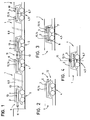
- the rail transport unit consists of a supporting structure of link 1 having two longitudinal ends front 2 and rear 3, by which it is located directly or indirectly mounted on two railway axle blocks (s) respectively before 4 and back 5 through an interface composite adapted before 6 and rear 7.
- the supporting structure 1 has at least two pieces of parallel sides 8 and 9 ending along the front 2 and rear longitudinal ends 3 separate or joined together.
- the interface composite 6 or 7 is integral with the axle block (x) corresponding 4 or 5.
- each axle block (x) 4 or 5 must be between each axle block (x) 4 or 5 and the corresponding ends of the supporting structure for connecting at least one articulation driving 10.
- Composite end interfaces 6 or 7 individually or simultaneously, with one of their ends, pads such as 11 and a hook hitch 12 for shock absorption and transmission of tensile force to the block axle (s) or bogie (s).
- the supporting structure 1 is free at least at one of its longitudinal ends, for example rear 3, according to a partial access opening 13 or total but sufficient for the passage of the load or of road loading in the case of loading by longitudinal or oblique penetration.
- Such coupling-locking means can exist on the other front composite interface 7.
- At least one of the composite interfaces of preferably the composite interface before 7, will present a loading / unloading pivot joint 14 allowing it to rotate in its together.
- the two pivot joints, on the one hand of rolling 10, and on the other hand loading / unloading 14, are juxtaposed or combined, or distinct, but with axes confused.
- the present invention covers two single joints than a double joint of pivoting along a common axis.
- the load-bearing connecting structure can be separated from the two composite interfaces.
- the loading-pivoting articulation 14, possibly confused with the rolling joint 10 from one end of the connecting support structure 1, is common or has a common axis 15 with the load-pivot joint at the end of the connecting support structure 1 immediately next.
- the integrated lifting means 16 of one or on the other end, or both create sufficient vertical release movement to realize the dissociation of one or the other end, or both, of the adjacent axle block (s), or its associated composite interface structure.
- Lateral displacement means for example of transverse running 17 on the ground, associated or not to the integrated lifting means 16, are intended to allow, in association with the lifting means, the dislocation of the load-bearing connecting structure by a vertical then lateral movement in order to decentralize the transverse access opening 13 and release it totally from the corresponding composite interface ( Figures 8 and 12).
- the loading / unloading modes in oblique and online are facilitated by aforementioned characteristics, concerning the opening transverse access 13 present at one of ends, for example rear, pivoting overall, but also the presence of structures linear carriers which will be discussed below.
- the supporting link structure 1 is intended to carry various loads, in particular road loads fully or partially incorporated.
- an articulated road assembly 18 vehicle carriers carrying cars such as 19 or a semi-trailer 20, or even one or more two standardized containers or swap bodies 21 and 22 ISO, fixed on their road base or supported by different ways, for example in terms of their classic corner pieces.
- the road load is carried by different means.
- linear internal carriers 23 and 24 present on along the side pieces 8 and 9 which hold the loading support plan at a level said lowered, i.e. below the upper level axle block (s) or bogie (s).
- these structures lower carriers are produced in the form of means of movement along paths 25 and 26 of bearing, sliding or guide, for wheels or additional rolling elements to the wheels (figure 10), or for mobile structures transverse movable carriers accommodating the wheels or the road load wheel trains at carry. It can be, for example, in this last case, trolleys or cradles movable along of the above paths (not shown).
- the structure link carrier has a bottom 27, for example flat, in the form of a plate 28 bringing together the lower edges of each of the flank pieces 8 and 9, to form an access ramp and a supporting plane for the road load (figure 11).
- the bottom 27 also constituting the access ramp is the plan load carrier and is located at a level said lowered.
- the rail transport unit can be opened or covered, and in this last case, present a fixed or removable cover.
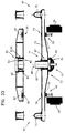
- the two flank pieces 8 and 9 of the supporting structure of link 1 extend longitudinally beyond each of their ends by extensions arm-shaped parallels such as 33 and 34, by straight example, coming in support relation with the corresponding composite interface mounted on its axle block (s) or bogie (s) ( Figures 12 to 28).
- the ends of the front and rear flank pieces are, for example, interconnected by a front link cross member and rear such as 35 and 36 ( Figures 12 to 28).
- the side pieces 8 and 9 can be fitted each along their face internal of a raceway, sliding or guide, intended to serve as a movement support for wheels of a vehicle, to an extension of the hub or to a carriage carrying a support accommodating the wheels of the road unit to be transported.
- the front end further comprises at the level rear ends of the flank pieces, the means integrated lifting gear 16 in the form of crutches extensible 37.38 with support sole ( Figures 8 and 12).
- the rolling means consist of lower rollers 39 and 40 shown schematically in Figure 12.
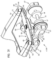
- the rail transport unit according to the invention can be mounted at each of its ends on a bogie 41 of the universal type, conventionally comprising a running gear, a carrying frame and a crapaudine 42 in which will come s' rotationally engaging a pivoting support 43 common to each of the connecting crosspieces 35 and 36 or two independent pivoting supports, crosspieces each carrying, at each of their ends, immobilization latch coupling means in two or three directions cooperating with suitable means.
- These crosspieces, pivoting link are each provided to connect and support the ends of each of the arms bordering the front end as shown in Figures 13 to 28.
- a single pivot can be used to on the one hand, the rolling pivoting and plus the swivel function of loading / unloading of the load-bearing structure immediately neighboring link in the case articulations with a common axis with that of the pivot of bogie.
- the wagon structure is a load-bearing structure meeting railway standards. It is intended for come to mate in a dissociable way by one or the other of its ends on a bogie interface common to two successive adjacent structures and identical for all the bogies of the same convoy.
- Bogie interface is the same for everyone the bogies of the same rail convoy.
- the invention aims, but not limiting, the use of classic bogies and universal.
- the bogie universal 41 traditionally consists of two axles 45 and 46 which, if applicable, have brake discs, e.g. 47, 48, 49 and 50.
- This chassis supports at least one articulation patella conventionally called crapaudine 57.
- This ball joint commonly receives pivoting the lower end structure of the supported car by the bogie.
- This common bogie interface adaptable to all common railway rolling bases called bogies allows to articulate and connect simultaneously the front and rear ends of two successive wagon structures according to the invention on and by the same bogie.
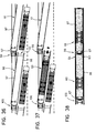
- This bogie interface is intended for serve as a common connecting piece for two structures successive wagons 60 and 61 of the same type in accordance with present invention ( Figures 36 to 38), for example removable and removable, comprising one end open rear 62 used for loading access autonomous, for example the road unit.
- This end rear is bordered by two arms 63 and 64 similar to arms 33 and 34 each terminated by a joining means 65, 66.
- the wagon structure also includes a front end 67 shaped like a "V" with two branches 68 and 69 converging along a point 70 which serves as pivot center 71.
- the bogie interface in question is present in the form of an interface crosspiece pivoting 72 mounted on the bogie 41 comprising a articulated central unit 73 common to the two structures successive wagons 60 and 61.
- This crosspiece 72 comprises at each of its ends a receiving support, for example centering pins 74 and 75 or erasable means or retractable, for example retractable fingers, it will be discussed later, for example of form conical, intended to receive in a dissociable way each of arms 63 and 64 of the open rear end 62 of one of the wagon structures supported by the bogie common.
- These receiving supports are aligned with the center of the sleeper. Next to these pawns or associates or integrated into them are provided locks additional to ensure coupling safety (not shown).
- reception supports constitute means of joining with complementary shapes provided at the ends 63 and 64 of the arms of the end open rear 62 of the wagon structure.
- the interface crosspiece 72 presented by elsewhere, on the underside, symmetrically in part and on either side of its articulated central assembly 73, a support area for example in the form of inserts 76, 77 opposite each of the reader 58 and 59, these plates serving as surface support and contact at the crosspiece 72.
- the interface cross member 72 can present on its upper side on either side of its central part two friction-bearing plates 78 and 79 for two pads opposite 80 and 81 mounted on springs 82 and 83 intended to make the contact support during roll movements and thereby even provide roll stability.
- the interface cross member 72 rests on the bogie, on the one hand, in its center in an articulated way, and on the other hand, laterally by its support surfaces on each of the sideboards thus offering the deflections according to the three degrees of freedom required between a wagon structure and a bogie.
- the articulated central assembly 73 turns out complex.
- the articulated central assembly 73 comprises also an upper articulation 86 resting or mounted on a mechanical element or structure 87 secured to the interface cross member 72.
- This upper articulation 86 is coaxial at the lower joint 84. These two joints therefore have the same geometric axis 88.
- the upper articulation 86 receives so separable or not the pivot center 71 of the front end at point 70 of the wagon structure constituting with it a means of articulation.
- the upper articulation 86 allows at least the pivoting movements in a horizontal plane referred to in the mode of loading / unloading using lateral offset in oblique.
- this ball joint function additional to the swivel function, can be filled simultaneously at the joint upper 86 as in the upper joint mixed described below.
- upper joint 86 is a spherical bearing 89 mounted on a pivot cylinder 90 secured to the central part of the cross member and coaxial with the axis vertical pivot of the basket.
- This spherical bearing develops around the pivot cylinder 90 and inside a cage 91 cylindrical with conical outer side surface 92 integral with or detachable from the front end 67 in tip of the wagon structure.
- the point 70 in "V" of the front end of the wagon structure is presented as a simple through bore, either cylindrical, either conical, coming to fit on the outer wall of the cage 91 of the spherical bearing.
- the front end 67 of the wagon structure is mounted directly on the when the interface cross member 72 is articulated above on an extension, an axis crossing end 67 or in any other way.
- Flank pieces 96 and 97 extend backward to a higher level by both arms parallel 63 and 64, like a stretcher delimiting with the adjacent edges flank pieces and the transverse end of the bottom the access opening 62 for the charge.
- the general conformation of the extremity rear 62 visible in the figures is such that the opening plan 101 thereof is located largely in withdrawal from the ends of arms 63 and 64.
- Flank pieces 96 and 97 extend forward by the two converging branches 68 and 69 arranged at approximately the same upper level as the arms 63 and 64 of the rear end 62. They have a general "V" shape whose tip is directed forward in a determined median zone by the general median vertical plane of the structure wagon and an upper horizontal plane which can be the one bounded by the two upper parallel edges flank pieces 96 and 97.
- the point 70 constituting the union of the two converging branches 68 and 69 is shaped so as to present an opening for example a bore end 102 intended to allow it to come mount in a dissociable way or not, but preferably not dissociable, on the upper part of the double joint 73.
- the rear end arms 63 and 64 62 are terminated by technical forms adapted to the end structures of the pivoting cross member bogie interface to form the joining means 65 and 66.
- the wagon structure When the end cones are fitted and locked, the wagon structure has a connection rigid transverse mechanical end incorporated by the bogie interface cross member.
- the 105,106 retractable fingers present at the two ends of the bogie interface are arranged in alignment with the central joint.
- end cones 103 and 104 each preceded, according to this variant, by a inclined ramp 111 and 112 on two successive slopes of penetration at the entrance of an opening 113 and 114 for backward erasure and upward release during the longitudinal movements of engagement and clearance of the ends of the arms 63 and 64.
- This coupling link can be blocked by additional end locks (not represented).
- the wagon structure has so optional near its ends of the means individual lifting possibly with rolling integrated or not, preferably autonomous, for example a crutch 115,116 similar to crutches 37 and 38 to each of the ends of each flank piece 96 and 97 (figure 35) and this at one end of the wagon structure or at both ends at the same time.
- a crutch 115,116 similar to crutches 37 and 38 to each of the ends of each flank piece 96 and 97 (figure 35) and this at one end of the wagon structure or at both ends at the same time.
- crutches targeted is that of a retractable and extendable stand for example telescopic, manual or hydraulic.
- each stand 115 and 116 of rolling means such as 117 and 118 with directional or fixed axis.
- Means can also be provided for bearings separated from the stands.
- means are provided for initial guidance over the side pieces 96 and 97, at the arms of the rear end.
- rollers such as 119 and 120 with vertical axis intended to ensure the centering then guiding the load along its flanks, for example along the lower edges 121,122 of the body of a 123 semi-trailer ( Figure 39).
- integrated means are provided load securing: semi-trailer, container, swap body etc ..., for example in the form of support on the upper or lateral arms or edges of flank pieces.
- the fixing is done by means conventional, for example twistlocks standardized or not.
- association and dissociation of successive wagon structures with the unique interface of bogie are carried out by nesting or dislocation of connecting means at the rear and possibly articulation means at the front.
- tapered bores 103 and 104 that have the ends of arms 63 and 64 of the rear end 62 of the wagon structure come fit onto the end centering pins of the crosspiece 72 interface with lock closure additional or get rid of them by simple vertical movements or without requiring the slightest lifting in the case of retractable fingers.
- the front end of the structure wagon carrying the spherical bearing is mounted on the pivot cylinder 90 or disengage from it in the case of a detachable variant according to which the conical central opening at the front end or bore can just as easily be mounted on the conical bearing head or extract from it by simple vertical movements.
- This overall lifting allows to extract in its whole and with its loading the unit of rail transport of the convoy, drop it off somewhere else pending, or insert it with its load in a another rail convoy.
- Figures 13 to 16 show the structure loaded by a semi-trailer separated from the convoy by lifting using a crane or gantry.
- the second mode concerns loading / unloading in line or longitudinal ( Figures 17 to 22). The movements are indicated by arrows.
- This loading / unloading mode requires a loading area called rails integrated in the ground.
- the transport unit rail is joined or separated by a vertical lifting or traveling movement or two handsets from its open cross end, solidarity-decoupling movement brought by the integrated lifting means, for example the extendable crutches for support and / or by means exteriors.
- the separation makes it possible to free the axle block (s) or bogie on whose interface the ends of the flank pieces were fitted.
- the road unit is loaded or unloaded, either directly along the load-bearing linear structures of displacement integrated into the Wagon, either indirectly, through one or more structure (s) transverse carrier (s) mobile (s) along the wagon structure on which or on which rests the undercarriage of the road unit.
- This road unit is coupled or secured or vice versa to a motor assembly 44, in view of its supply or evacuation in line on the quay, following the general direction of the convoy rail.
- a rear end having a deep and remote opening allows the whole engine 44 to stay on the ground during supply maneuvers or recovery of the semi-trailer.
- Loading / unloading takes place in bringing the front end oblique after detachment from the axle block (s) or bogie before by any means, for example by crutches, then offset obliquely by rolling on the quay loading, operation during which the structure carrier as a whole pivots around its rear end by pivoting support on the axle block (s) or rear bogie.
- the running gear of the unit road to be loaded is carried by the structures linear internal carriers 23 and 24 or mounted on transverse load-bearing structures, cradles or carts. Moving along the flank pieces 8 and 9 or 96 and 97, to or from its position of transport, is provided by integrated motor means or preferably by the road motor vehicle.
- the supporting structure is then moved laterally towards the axle block (x) or bogie by a overall pivoting movement in the same way as previously, but in reverse order.
- Lifting means for example integrated in the form of crutches, raise the front ends flank pieces, and come to place them opposite securing-locking means provided on the interface of the axle block (x) or bogie.
- the supporting structure After coupling and locking, the supporting structure is ready in the convoy with its re-loading for rail transport.
- Means for lifting the rear end integrated into the wagon or exterior structure will allow, after opening additional locks, to separate the joining means and obtain the dissociation of the wagon structure from the interface of bogie.
- a rotational movement around the end front will ensure the clearance of the rear end by an oblique offset.
- Lifting means at both ends allow the removal of the wagon structure by transverse or longitudinal shift.
- the means described above will provide the possibility to choose and carry out the loading / unloading best suited to the load (container, road unit or other) and at the configuration of the station handling area, train and constraints and peculiarities of the sorting operation.
Landscapes
- Engineering & Computer Science (AREA)
- Transportation (AREA)
- Mechanical Engineering (AREA)
- Handcart (AREA)
- Loading Or Unloading Of Vehicles (AREA)
- Chain Conveyers (AREA)
- Body Structure For Vehicles (AREA)
Claims (40)
- Schienentransporteinheit, die zwei Achssätze oder zwei Drehgestelle verbindet, mit einem an einer seiner Endseiten offenen Waggonaufbau aus zwei Seitenteilen und einer abgesenkten Bodenfläche, wobei die Seitenteile an der einen ihrer Endseiten in Form einer Gabeldeichsel enden und mit der Bodenfläche eine zurückgesetzte Zugangsöffnung für die Ladung oder eine straßengebundene Beladung, insbesondere einer vollständig oder teilweise zusammengesetzten Straßentransporteinheit, begrenzen, dadurch gekennzeichnet, daß der Waggonaufbau mittels eines zusammengesetzten Zwischenglieds, das die Zug- und Stoßkräfte überträgt, an beiden Achssätzen oder Drehgestellen befestigt ist, Waggonaufbau dessen Ankopplung an das zusammengesetzte Zwischenglied des Drehgestells an den Endabschnitten der Seitenteile erfolgt, und daß dieser Transportaufbau an dem zusammengesetzten Zwischenglied zumindest eines, zumindest mit dessen die Zugangsöffnung aufweisenden Endabschnitt verbundenen Achssatzes oder Drehgestells lösbar befestigt ist, um den Durchtritt für die Ladung oder die straßengebundene Beladung auf oder in die Transportstruktur durch die Einlaß- oder Ausbringöffnung vollständig freizugeben, und daß diese für einen direkten Zugang der Ladung vom Boden aus zumindest mit dem Zugangsendabschnitt bis auf den Erdboden absetzbar ist.
- Transporteinheit nach Anspruch 1, dadurch gekennzeichnet, daß das zusammengesetzte Zwischenglied mit dem Achssatz oder dem Drehgestell/den Drehgestellen fest verbunden ist.
- Transporteinheit nach Anspruch 1 oder 2, dadurch gekennzeichnet, daß die beiden Seitenteile, die an einem Ende in zwei getrennten Endstücken enden, am gegenüberliegenden Ende in zwei zusammengeführten Endstücken enden.
- Transporteinheit nach einem der Ansprüche 1 bis 3, dadurch gekennzeichnet, daß jedes zusammengesetzte Zwischenglied wenigstens ein Mittel zum Verschwenken mit Rollen, Mittel zum Ankuppeln/Verriegeln an den Endstücken des Waggonaufbaus, Mittel zur Übertragung der Zugkraft und Mittel zur Aufnahme der Stöße aufweist.
- Transporteinheit nach einem der Ansprüche 1 bis 4, dadurch gekennzeichnet, daß das Mittel zur Übertragung der Zugkraft die mechanische Struktur des Zwischenglieds ist.
- Transporteinheit nach einem der Ansprüche 1 bis 5, dadurch gekennzeichnet, daß zumindest ein Zwischenglied Puffer und einen Zughaken aufweist.
- Transporteinheit nach einem der Ansprüche 1 bis 6, dadurch gekennzeichnet, daß sie gegenüberliegend entlang den Innenseiten jedes Seitenteils Verschiebe- bzw. Haltemittel zum Halten, zum Instellungbringen oder Ausfahren der straßengebundenen Ladung aufweist.
- Transporteinheit nach Anspruch 7, dadurch gekennzeichnet, daß die Verschiebemittel Roll-, Gleit- oder Führungsbahnen für die Räder oder Rollelemente, zusätzlich zu den Rädern oder transversale Tragestrukturen der Räder oder der Radachsen der zu befördernden Straßentransporteinheit, in Längsrichtung entlang den Seitenteilen bewegliche Quereinrichtungen sind.
- Transporteinheit nach Anspruch 7 oder 8, dadurch gekennzeichnet, daß die durch die Verschiebe- bzw. Haltemittel gebildete Beladungsebene abgesenkt ist.
- Transporteinheit nach einem der Ansprüche 1 bis 9, dadurch gekennzeichnet, daß zumindest eines der zusammengesetzten Zwischenglieder ein zweifaches Schwenkgelenk bestehend aus einem Gelenk für die Transportbewegung und einem Gelenk für das Beladen/Entladen aufweist.
- Transporteinheit nach den Ansprüchen 1 und 10, dadurch gekennzeichnet, daß das zweifache Schwenkgelenk zwei einander folgenden Waggonaufbauten auf einem Achssatz oder Drehgestell gemeinsam ist.
- Transporteinheit nach einem der Ansprüche 1 bis 11, dadurch gekennzeichnet, daß der Endabschnitt des mit dem ein zweifaches Schwenkgelenk aufweisenden zusammengesetzten Zwischenglied verbundenen Waggonaufbaus von dem zusammengesetzten Zwischenglied trennbar ist.
- Transporteinheit nach einem der Ansprüche 1 bis 12, dadurch gekennzeichnet, daß der Waggonaufbau an seiner der offenen Endseite gegenüberliegenden Endseite Schwenkmittel in bezug auf das Zwischenglied, die ihm in seiner Gesamtheit ein Verschwenken für Be- oder Entladevorgänge ermöglichen, aufweist.
- Transporteinheit nach einem der Ansprüche 1 bis 13, dadurch gekennzeichnet, daß der Waggonaufbau Mittel, die sein vertikales Ergreifen ermöglichen, aufweist.
- Transporteinheit nach einem der Ansprüche 1 bis 14, dadurch gekennzeichnet, daß der Waggonaufbau an jedem seiner Seitenteile Haltemittel für wenigstens einen Transportbehälter oder einen Container oder eine Straßenfahrzeugkarosserie aufweist.
- Transporteinheit nach den Ansprüchen 1 bis 5, dadurch gekennzeichnet, daß der Waggonaufbau von dem zusammengesetzten Zwischenglied des Achssatzes oder des Drehgestells/der Drehgestelle in der Nähe der hinteren, offenen Endseite durch Verschwenken oder durch Anheben und anschließendes Verschwenken der entsprechenden Endseite zum Zwecke eines relativen seitlichen Ausschwenkens beim Be-/Entladen in Schrägstellung trennbar ist.
- Transporteinheit nach einem der Ansprüche 1 bis 16, dadurch gekennzeichnet, daß der Waggonaufbau in der Nähe seiner hinteren, offenen Endseite integrierte Hebemittel und/oder Mittel zum Rollen auf dem Boden für seine Schwenkbewegung als Einheit hinsichtlich des seitlichen Ausschwenkens beim Be-/Entladen in Schrägstellung aufweist.
- Transporteinheit nach Anspruch 1 oder 11, dadurch gekennzeichnet, daß die Bodenfläche als Zugangsrampe vom Erdboden aus nutzbar ist.
- Transporteinheit mit einem auf zwei Achssätzen oder Drehgestellen aufliegenden Verbindungswaggonaufbau für die Be-/Entladung und den Schienentransport einer Ladung oder einer teilweise oder vollständig zusammengesetzten Straßentransporteinheit, dadurch gekennzeichnet, daß die zwei Seitenteile in Längsrichtung in ihrem oberen Abschnitt einerseits an dem hinteren Ende des Waggonaufbaus durch zwei an ihren Enden durch eine Halte-/Schwenkverbindung an einer Stützeinrichtung des Achssatzes oder Drehgestells zusammengeführte Abschnitte und andererseits am vorderen Ende durch zwei parallele Arme, wobei die Endabschnitte verschieden sind und auf den Endstücken eines Querträgers an dem Achssatz oder Drehgestell lösbar aufliegen, verlängert sind, daß die Seitenteile im unteren Abschnitt durch eine tragende Querverbindung für die Fahrachsen einer straßengebundenen Einheit zusammengeführt sind, daß durch auf die Mittel zum Querrollen montierte vertikale Hebemittel zumindest an dem vorderen Endabschnitt das Absenken der Zugangsöffnung bis auf den Erdboden und das anschließende Wiederanheben möglich ist und daß die Seitenteile entlang jeder ihrer Flächen gegenüberliegende Haltevorrichtungen für einen Straßentransportbehälter oder die Karosserie eines Straßenfahrzeugs aufweisen.
- Transporteinheit nach Anspruch 19, dadurch gekennzeichnet, daß durch die zwei parallelen, durch die parallelen Arme in Längsrichtung verlängerten Seitenteile eine nach unten offene Bodenfläche und als Abschluß ein vorderes, in Längsrichtung durch die beiden parallelen Arme erweitertes, vollständig offenes Ende und ein durch Erweiterung nach hinten der Halte-/Schwenkeinrichtung in Längsrichtung verlängertes hinteres Ende eingeschlossen ist, wobei jede Erweiterung trennbar auf einer schwenkbaren Stützeinrichtung befestigt ist, die jeder Achssatz oder jedes Drehgestell aufweist.
- Transporteinheit nach Anspruch 19 oder 20, dadurch gekennzeichnet, daß die Hebemittel, die an der Basis des vorderen Endes jedes Seitenteils vorgesehen sind, Teleskopstangen sind.
- Transporteinheit nach Anspruch 21, dadurch gekennzeichnet, daß die Stangen abnehmbar mit einer beweglichen Zugangsrampe verbunden sind.
- Transporteinheit nach Anspruch 19 oder 20, dadurch gekennzeichnet, daß die Rollmittel, die an den Unterseiten der vorderen Enden der Seitenteile vorgesehen sind, Rollen sind.
- Transporteinheit nach Anspruch 19 oder 20, dadurch gekennzeichnet, daß der schwenkbare Querträger des Achssatzes oder Drehgestells den Gelenkzapfen der hinteren Erweiterung aufweist.
- Transporteinheit nach Anspruch 24, dadurch gekennzeichnet, daß die schwenkbare Querleiste ein einziges, gemeinsames, schwenkbares Element zweier aufeinanderfolgender Aufbauten ist.
- Transporteinheit nach einem der Ansprüche 19 bis 23, dadurch gekennzeichnet, daß das Verschwenken der Stützauflage des Achssatzes oder des Drehgestells bezogen auf den Achssatz oder das Drehgestell unabhängig von dem Verschwenken des Waggonaufbaus bezogen auf den Achssatz oder das Drehgestell ist.
- Transporteinheit nach Anspruch 24, dadurch gekennzeichnet, daß die an jedem Achssatz oder Drehgestell angeordnete, verschwenkbare Querleiste eine Führ- und Verriegelungseinheit ist.
- Transporteinheit nach Anspruch 23 oder 25, dadurch gekennzeichnet, daß die schwenkbare Querleiste des Achssatzes oder Drehgestells zu beiden Seiten eines zentralen Drehpunktes symmetrisch ist.
- Transporteinheit nach einem der Ansprüche 26 bis 28, dadurch gekennzeichnet, daß der Schwenkträger jedes Achssatzes oder Drehgestells eine schwenkbare, an dem Spurzapfen des Achssatzes oder Drehgestells befestigte Querleiste ist.
- Transporteinheit nach Anspruch 29, dadurch gekennzeichnet, daß die schwenkbare Querleiste des Zwischenglieds und die Spitze des vorderen Endabschnitts eines Waggonaufbaus mittels einer gemeinsamen gelenkigen Einheit zum verschwenken mit dem Spurzapfen des Drehgestells verbunden sind und daß die V-förmige Spitze des vorderen Endabschnitts des Waggonaufbaus durch vertikale Bewegungen von der gemeinsamen gelenkigen Einheit trennbar ist und der gegenüberliegende Endabschnitt des nachfolgenden Waggonaufbaus durch vertikale und/oder horizontale Bewegungen von den Endabschnitten der schwenkbaren Querleiste trennbar ist.
- Verfahren zum Be-/Entladen und zur Bildung eines Abschnitts eines schienengebundenen Zugs mittels der Schienentransporteinheit nach einem der Ansprüche 1 bis 30 für den Schienentransport von Ladungen, teilweise oder vollständig zusammengesetzten Straßentransporteinheiten oder selbst beladenen Lastkraftzügen, nach dem der Transportaufbau an einer seiner Endseiten abgetrennt und mit dieser Endseite zum Erzielen eines Querabstandes zur Längsausrichtung des Schienenzugs verschwenkt wird, dadurch gekennzeichnet, daß die Transporteinheit nach einem der vorstehenden Ansprüche eingesetzt wird, so montiert, daß sie an der einen oder anderen seiner Endseiten von dem einen oder anderen der zwei Achssätze oder Drehgestelle getrennt wird, daß der für das Verschwenken vorgesehene Transportaufbau bis zum Bodenkontakt abgesenkt wird, während der andere Endabschnitt nach dem Verschwenken um den gegenüberliegenden Achssatz oder das Drehgestell an diesem befestigt bleibt, daß das Fahrzeug durch die Zugangsöffnung in den Innenraum zwischen den Seitenteilen geführt wird, daß die Straßenverkehrseinheit mit ihrer Achse an den tragenden Längsstrukturen zum Verschieben oder den tragenden Querstrukturen befestigt wird, daß die mit der straßengebundenen Einheit verbundene Zugmaschine von der getragenen und/oder gezogenen Einheit, der aufsetzbaren Karosserie, dem Sattelauflieger oder dgl. abgetrennt wird, daß die Schienentransporteinheit mittels erneutem An- oder Emporheben des freien Endabschnitts und anschließendem Verschwenken wiederhergestellt wird, und daß sie mit dem Achssatz oder dem Drehgestell zusammengeführt wird, um wieder auf dem Zwischenglied des Achssatzes oder Drehgestells abgesetzt und mit diesem verbunden zu werden.
- Verfahren zum Be-/Entladen und zur Bildung eines Schienenzugs nach Anspruch 31, dadurch gekennzeichnet, daß die Räder der straßengebundenen Einheit zum Transport in den tragenden, beweglichen Querstrukturen durch Drücken oder Ziehen entlang der tragenden Längsstrukturen zum Verschieben bis in die Transportposition verbracht werden.
- Verfahren zum Be-/Entladen und zur Bildung einer Schienentransporteinheit mittels einer Transporteinheit nach einem der Ansprüche 1 bis 30 zum Schienentransport von Fahrzeugen oder straßengebundenen Zügen, die selbst beladen sind, dadurch gekennzeichnet, daß die trennbar befestigte Schienenzugstruktur eingesetzt wird, daß diese an ihrem offenen Endabschnitt bis zu dessen Trennung von dem Achssatz oder Drehgestell an- oder emporgehoben oder verschoben wird, daß der Waggonaufbau auf den Boden abgesenkt wird, daß die straßengebundene Einheit verschoben wird, um ihr den Durchtritt durch den offenen Endabschnitt und das Plazieren auf den tragenden Querstrukturen, um sie endgültig an der Tragestruktur festzulegen, zu ermöglichen, daß die Zugmaschine von der getragenen und/oder gezogenen Einheit, der aufsetzbaren Karosserie, dem Sattelauflieger oder dgl. getrennt wird, daß der Schienenzug durch erneutes An- oder Emporheben oder durch Verschieben des freien Endabschnitts in entgegengesetzter Richtung und anschließendes Absetzen auf und Verbinden mit dem Achssatz oder Drehgestell wiederhergestellt wird.
- Verfahren zum Be-/Entladen und zur Bildung einer Schienentransporteinheit nach einem der Ansprüche 1 bis 33, dadurch gekennzeichnet, daß der Waggonaufbau in seiner Gesamtheit angehoben und gleichzeitig von dem einen wie von dem anderen Achssatz oder Drehgestell getrennt, mittels eines Hebegerätes in seiner Gesamtheit seitlich versetzt, auf dem Boden oder einer Laderampe abgesetzt, dann beladen oder entladen und in umgekehrter Vorgehensweise wieder zurückgesetzt wird.
- Verfahren zum Be-/Entladen nach Anspruch 34, dadurch gekennzeichnet, daß der Waggonaufbau in seiner Gesamtheit angehoben, gleichzeitig von dem einen wie dem anderen Achssatz oder Drehgestell getrennt und in ihrer Gesamtheit versetzt wird, um in einen anderen Schienenzug eingesetzt zu werden.
- Verfahren zum Be-/Entladen und zur Bildung einer Schienentransporteinheit mittels einer Transporteinheit nach einem der Ansprüche 1 bis 35, dadurch gekennzeichnet, daß der Tragaufbau an einem zusammengesetzten Zwischenglied eines gemeinsamen Achssatzes oder Drehgestells zweier aufeinanderfolgender Tragaufbauten befestigt ist, das deren jeweiliges unabhängiges An- und Abkuppeln ermöglicht.
- Verfahren zum Be-/Entladen nach einem der Ansprüche 34 bis 36, dadurch gekennzeichnet, daß das Zwischenglied des Achssatzes oder Drehgestells an einem einzelnen Tragaufbau angeordnet ist und Puffer aufweist.
- Verfahren zum Be-/Entladen nach einem der Ansprüche 34 bis 37, dadurch gekennzeichnet, daß die straßengebundene Ladung durch den Waggonaufbau gestützt ist und entlang dieser durch Längsstrukturen in Form von in die Tragstruktur integrierten Roll- oder Gleitschienen verschoben wird.
- Verfahren zum Be-/Entladen nach Anspruch 38, dadurch gekennzeichnet, daß die straßengebundene Ladung durch den Waggonaufbau gehalten ist und entlang diesem durch entlang des Waggonaufbaus verschiebliche, tragende Querstrukturen verschoben wird.
- Verwendung des Verfahrens zum Be-/Entladen und zur Bildung einer Schienentransporteinheit nach einem der Ansprüche 1 bis 39 für einen Schienentransport von Fahrzeugen oder straßengebundenen Lastzügen, die selbst beladen sind.
Applications Claiming Priority (6)
| Application Number | Priority Date | Filing Date | Title |
|---|---|---|---|
| FR9110590 | 1991-08-21 | ||
| FR9110590A FR2680492B1 (fr) | 1991-08-21 | 1991-08-21 | Unite de transport ferroviaire porteuse d'une charge routiere. |
| FR9202763 | 1992-03-04 | ||
| FR9202763A FR2688180B1 (fr) | 1992-03-04 | 1992-03-04 | Interface pivotante unique entre un bogie commun et deux structures wagon adjacentes. |
| FR9202764A FR2688179B1 (fr) | 1992-03-04 | 1992-03-04 | Structure wagon deposable articulee a une interface de bogie commune a deux structures adjacentes. |
| FR9202764 | 1992-03-04 |
Publications (2)
| Publication Number | Publication Date |
|---|---|
| EP0528741A1 EP0528741A1 (de) | 1993-02-24 |
| EP0528741B1 true EP0528741B1 (de) | 1998-07-08 |
Family
ID=27252502
Family Applications (1)
| Application Number | Title | Priority Date | Filing Date |
|---|---|---|---|
| EP92440097A Expired - Lifetime EP0528741B1 (de) | 1991-08-21 | 1992-08-21 | Trennbare Güterzugeinheit, insbesondere für den Transport von Strassenfahrzeugen |
Country Status (7)
| Country | Link |
|---|---|
| US (1) | US6095055A (de) |
| EP (1) | EP0528741B1 (de) |
| AT (1) | ATE168083T1 (de) |
| AU (1) | AU670756B2 (de) |
| CA (1) | CA2116006A1 (de) |
| DE (1) | DE69226138T2 (de) |
| WO (1) | WO1993003945A1 (de) |
Families Citing this family (15)
| Publication number | Priority date | Publication date | Assignee | Title |
|---|---|---|---|---|
| SE9403544D0 (sv) * | 1994-10-18 | 1994-10-18 | Lars Berglund | Sätt och anordning för lastning och lossning av godståg |
| SE503925C2 (sv) * | 1995-05-26 | 1996-09-30 | Jan Eriksson | Järnvägsvagn |
| DE19546300C1 (de) * | 1995-10-04 | 1997-04-30 | Matthias Gradenwitz | Cargosystem mit Rotationsbrücken zum Be- und Entladen von Kraftfahrzeugen auf Eisenbahnzügen |
| JP2001522758A (ja) * | 1997-11-05 | 2001-11-20 | ダイムラークライスラー アーゲー | 鉄道車両システム |
| DE10104005A1 (de) * | 2001-01-31 | 2002-08-01 | Werner Haag | Verfahren und Niederflurfahrzeug zum Transport von Strassenfahrzeugen auf der Schiene |
| US6510800B1 (en) | 2001-10-12 | 2003-01-28 | Gunderson, Inc. | Multi-unit railroad freight car for carrying cargo containers between container well units |
| US6546878B1 (en) | 2001-10-12 | 2003-04-15 | Gunderson, Inc. | Multi-unit railroad freight car for carrying cargo containers |
| US20090151596A1 (en) * | 2007-12-12 | 2009-06-18 | William Harvey Sproat | Fastload rail carrier for motor vehicles, freight and passengers |
| US7757610B2 (en) | 2008-07-30 | 2010-07-20 | Gunderson Llc | Shortened container well |
| CN102395501B (zh) * | 2009-04-16 | 2014-09-24 | K科技有限公司 | 铁路货车及其装载方法 |
| US8616564B2 (en) * | 2009-12-07 | 2013-12-31 | Paceco Corp. | Cargo container handling cart and system using same |
| US8291592B2 (en) * | 2010-03-17 | 2012-10-23 | Gunderson Llc | Method of lengthening a container well of a railcar |
| US8177461B2 (en) | 2010-04-09 | 2012-05-15 | Gunderson Llc | Transport and storage of wheelsets |
| CN104494612A (zh) * | 2015-01-05 | 2015-04-08 | 齐齐哈尔轨道交通装备有限责任公司 | 铁路货车 |
| PL237854B1 (pl) * | 2018-03-15 | 2021-06-14 | Inst Pojazdow Szynowych Tabor | Wagon, zwłaszcza do transportu kombinowanego kolejowego- -drogowego |
Family Cites Families (10)
| Publication number | Priority date | Publication date | Assignee | Title |
|---|---|---|---|---|
| US2246543A (en) * | 1938-11-28 | 1941-06-24 | Jay C Smith | Railroad car for transporting vehicles |
| DE3234374C2 (de) * | 1982-09-16 | 1985-04-25 | Waggonfabrik Talbot, 5100 Aachen | Eisenbahn-Güterwagen zum Transport von Straßenfahrzeugen |
| US4653966A (en) * | 1986-01-08 | 1987-03-31 | Trailer Rail Partners | Drop-deck intermodal bogie |
| EP0293359B1 (de) * | 1987-05-14 | 1990-07-18 | Austria Metall Aktiengesellschaft | Höhenverstellbarer Tiefladewaggon für Huckepackverkehr |
| US4961676A (en) * | 1987-12-11 | 1990-10-09 | Intermotra | Goods transport systems which are transformable into rail vehicles, and rail bogies for use therewith |
| NL8901499A (nl) * | 1989-06-13 | 1991-01-02 | Alpha Engineering Ingenieurs E | Spoorwegsysteem en draaistel, eindwagen, voertuigfreem, draagorgaan en oplegger daarvoor. |
| FR2663896B1 (fr) * | 1990-06-29 | 1993-07-02 | Sambre & Meuse Usines | Systeme de transport rail-route pour remorques ou conteneurs. |
| US5216956A (en) * | 1990-10-12 | 1993-06-08 | Adams Jr George W | Truck train system having a removable first truck and a second truck with a load platform and an extendable center sill |
| US5222443A (en) * | 1992-05-13 | 1993-06-29 | Knorr Brake Holding Corporation | Railway ramp car |
| FR2694913B1 (fr) * | 1992-08-20 | 1994-09-23 | Lohr Ind | Ensemble d'accouplement entre deux structures wagon successives et un bogie commun. |
-
1992
- 1992-08-21 EP EP92440097A patent/EP0528741B1/de not_active Expired - Lifetime
- 1992-08-21 WO PCT/FR1992/000816 patent/WO1993003945A1/fr active Application Filing
- 1992-08-21 CA CA002116006A patent/CA2116006A1/fr not_active Abandoned
- 1992-08-21 DE DE69226138T patent/DE69226138T2/de not_active Expired - Lifetime
- 1992-08-21 US US08/193,203 patent/US6095055A/en not_active Expired - Fee Related
- 1992-08-21 AT AT92440097T patent/ATE168083T1/de not_active IP Right Cessation
- 1992-08-21 AU AU25043/92A patent/AU670756B2/en not_active Ceased
Also Published As
| Publication number | Publication date |
|---|---|
| AU670756B2 (en) | 1996-08-01 |
| CA2116006A1 (fr) | 1993-03-04 |
| AU2504392A (en) | 1993-03-16 |
| EP0528741A1 (de) | 1993-02-24 |
| DE69226138D1 (de) | 1998-08-13 |
| US6095055A (en) | 2000-08-01 |
| DE69226138T2 (de) | 1999-02-18 |
| ATE168083T1 (de) | 1998-07-15 |
| WO1993003945A1 (fr) | 1993-03-04 |
Similar Documents
| Publication | Publication Date | Title |
|---|---|---|
| EP0320420B1 (de) | In Eisenbahnwagen umwandelbare Fahrzeuge und Transportvorrichtungen und Drehgestelle dafür | |
| EP0528741B1 (de) | Trennbare Güterzugeinheit, insbesondere für den Transport von Strassenfahrzeugen | |
| EP2598392B1 (de) | Universelles system für laden/entladen und schienentransport für sattelanhänger | |
| EP0584026B1 (de) | Kupplungseinheit zwischen zwei aufeinander folgenden Waggons und einem gemeinsamen Drehgestell | |
| EP1292476B1 (de) | Transport- und scrägverladesystem für waggons in einem bahnhof für den kombinierten schienen-/strassen- transport und zugehöriges verfahren | |
| EA036512B1 (ru) | Способ погрузки (выгрузки) автомобильного полуприцепа на вагон-кенгуру и вагон-кенгуру, подходящий для этого способа | |
| EP1349763A1 (de) | Eisenbahneinheit mit schwenklagerkonstruktion zum kombinierten schienen/strassen-transport entweder eines sattelaufliegers oder von zwei motorfahrzeugen | |
| EP1874584B1 (de) | Schienenfahrzeug zum transport von strassenfahrzeugen mit zwischen einer transportposition und einer position zum bewegen zwischen schienenfahrzeugen beweglichen plattformen und aus solchen schienenfahrzeugen bestehender zug | |
| HU221835B1 (hu) | Vasúti kocsi | |
| EP0672566B1 (de) | Verfahren und System zum Be- und Entladen von Waggons für den Transport von Strassenfahrzeugen sowie Ladewaggon hierfür | |
| EP0112778B1 (de) | Tragrahmen zum Aufnehmen eines Wagens oder Güterbehälters für Verwendung auf Strasse, Schiene und Wasser | |
| EP0426589A1 (de) | In ein Schienenfahrzeug umwandelbarer Tieflader | |
| EP0032471B1 (de) | Demontierbarer Waggon für die technische Koordination des kombinierten Schienen- und Strassenverkehrs | |
| FR2680492A1 (fr) | Unite de transport ferroviaire porteuse d'une charge routiere. | |
| FR2624445A1 (fr) | Vehicules de transport mixte rail-route | |
| EP0265398B1 (de) | Sattelanhänger für Schiene und Strasse | |
| FR2666767A1 (fr) | Structure transversale d'extremite permettant la transformation rail-route d'une unite routiere. | |
| FR2534870A1 (fr) | Semi-remorque pour la coordination technique rail-route et wagon charge de cette semi-remorque | |
| FR2482031A2 (fr) | Wagon demontable pour la coordination technique du transport rail-route | |
| FR2688179A1 (fr) | Structure wagon deposable articulee a une interface de bogie commune a deux structures adjacentes. | |
| FR2516029A1 (fr) | Dispositif pour le transport routier de wagons ferroviaires | |
| FR2743537A1 (fr) | Systeme de transbordement pour le transport combine | |
| FR2688180A1 (fr) | Interface pivotante unique entre un bogie commun et deux structures wagon adjacentes. | |
| BE538724A (de) | ||
| FR2638414A1 (fr) | Vehicules et dispositifs de transport transformables en wagons |
Legal Events
| Date | Code | Title | Description |
|---|---|---|---|
| PUAI | Public reference made under article 153(3) epc to a published international application that has entered the european phase |
Free format text: ORIGINAL CODE: 0009012 |
|
| AK | Designated contracting states |
Kind code of ref document: A1 Designated state(s): AT BE CH DE DK ES GB GR IT LI LU MC NL PT SE |
|
| 17P | Request for examination filed |
Effective date: 19930724 |
|
| R17P | Request for examination filed (corrected) |
Effective date: 19930816 |
|
| 17Q | First examination report despatched |
Effective date: 19950220 |
|
| GRAG | Despatch of communication of intention to grant |
Free format text: ORIGINAL CODE: EPIDOS AGRA |
|
| GRAG | Despatch of communication of intention to grant |
Free format text: ORIGINAL CODE: EPIDOS AGRA |
|
| GRAH | Despatch of communication of intention to grant a patent |
Free format text: ORIGINAL CODE: EPIDOS IGRA |
|
| GRAH | Despatch of communication of intention to grant a patent |
Free format text: ORIGINAL CODE: EPIDOS IGRA |
|
| GRAA | (expected) grant |
Free format text: ORIGINAL CODE: 0009210 |
|
| AK | Designated contracting states |
Kind code of ref document: B1 Designated state(s): AT BE CH DE DK ES GB GR IT LI LU MC NL PT SE |
|
| PG25 | Lapsed in a contracting state [announced via postgrant information from national office to epo] |
Ref country code: GR Free format text: LAPSE BECAUSE OF FAILURE TO SUBMIT A TRANSLATION OF THE DESCRIPTION OR TO PAY THE FEE WITHIN THE PRESCRIBED TIME-LIMIT Effective date: 19980708 Ref country code: ES Free format text: THE PATENT HAS BEEN ANNULLED BY A DECISION OF A NATIONAL AUTHORITY Effective date: 19980708 |
|
| REF | Corresponds to: |
Ref document number: 168083 Country of ref document: AT Date of ref document: 19980715 Kind code of ref document: T |
|
| REG | Reference to a national code |
Ref country code: CH Ref legal event code: EP |
|
| REF | Corresponds to: |
Ref document number: 69226138 Country of ref document: DE Date of ref document: 19980813 |
|
| PG25 | Lapsed in a contracting state [announced via postgrant information from national office to epo] |
Ref country code: PT Free format text: LAPSE BECAUSE OF FAILURE TO SUBMIT A TRANSLATION OF THE DESCRIPTION OR TO PAY THE FEE WITHIN THE PRESCRIBED TIME-LIMIT Effective date: 19981008 Ref country code: DK Free format text: LAPSE BECAUSE OF FAILURE TO SUBMIT A TRANSLATION OF THE DESCRIPTION OR TO PAY THE FEE WITHIN THE PRESCRIBED TIME-LIMIT Effective date: 19981008 |
|
| GBT | Gb: translation of ep patent filed (gb section 77(6)(a)/1977) |
Effective date: 19981008 |
|
| PG25 | Lapsed in a contracting state [announced via postgrant information from national office to epo] |
Ref country code: MC Free format text: LAPSE BECAUSE OF NON-PAYMENT OF DUE FEES Effective date: 19990228 |
|
| PLBE | No opposition filed within time limit |
Free format text: ORIGINAL CODE: 0009261 |
|
| STAA | Information on the status of an ep patent application or granted ep patent |
Free format text: STATUS: NO OPPOSITION FILED WITHIN TIME LIMIT |
|
| 26N | No opposition filed | ||
| PGFP | Annual fee paid to national office [announced via postgrant information from national office to epo] |
Ref country code: GB Payment date: 20010713 Year of fee payment: 10 |
|
| PGFP | Annual fee paid to national office [announced via postgrant information from national office to epo] |
Ref country code: BE Payment date: 20010717 Year of fee payment: 10 |
|
| PGFP | Annual fee paid to national office [announced via postgrant information from national office to epo] |
Ref country code: LU Payment date: 20010725 Year of fee payment: 10 |
|
| PGFP | Annual fee paid to national office [announced via postgrant information from national office to epo] |
Ref country code: SE Payment date: 20010823 Year of fee payment: 10 |
|
| PGFP | Annual fee paid to national office [announced via postgrant information from national office to epo] |
Ref country code: AT Payment date: 20010829 Year of fee payment: 10 |
|
| REG | Reference to a national code |
Ref country code: GB Ref legal event code: IF02 |
|
| PG25 | Lapsed in a contracting state [announced via postgrant information from national office to epo] |
Ref country code: LU Free format text: LAPSE BECAUSE OF NON-PAYMENT OF DUE FEES Effective date: 20020821 Ref country code: GB Free format text: LAPSE BECAUSE OF NON-PAYMENT OF DUE FEES Effective date: 20020821 Ref country code: AT Free format text: LAPSE BECAUSE OF NON-PAYMENT OF DUE FEES Effective date: 20020821 |
|
| PG25 | Lapsed in a contracting state [announced via postgrant information from national office to epo] |
Ref country code: SE Free format text: LAPSE BECAUSE OF NON-PAYMENT OF DUE FEES Effective date: 20020822 |
|
| PGFP | Annual fee paid to national office [announced via postgrant information from national office to epo] |
Ref country code: NL Payment date: 20020830 Year of fee payment: 11 |
|
| PG25 | Lapsed in a contracting state [announced via postgrant information from national office to epo] |
Ref country code: BE Free format text: LAPSE BECAUSE OF NON-PAYMENT OF DUE FEES Effective date: 20020831 |
|
| BERE | Be: lapsed |
Owner name: *LOHR INDUSTRIE Effective date: 20020831 |
|
| EUG | Se: european patent has lapsed | ||
| GBPC | Gb: european patent ceased through non-payment of renewal fee |
Effective date: 20020821 |
|
| PG25 | Lapsed in a contracting state [announced via postgrant information from national office to epo] |
Ref country code: NL Free format text: LAPSE BECAUSE OF NON-PAYMENT OF DUE FEES Effective date: 20040301 |
|
| NLV4 | Nl: lapsed or anulled due to non-payment of the annual fee |
Effective date: 20040301 |
|
| PGFP | Annual fee paid to national office [announced via postgrant information from national office to epo] |
Ref country code: CH Payment date: 20110711 Year of fee payment: 20 |
|
| PGFP | Annual fee paid to national office [announced via postgrant information from national office to epo] |
Ref country code: DE Payment date: 20110827 Year of fee payment: 20 |
|
| PGFP | Annual fee paid to national office [announced via postgrant information from national office to epo] |
Ref country code: IT Payment date: 20110825 Year of fee payment: 20 |
|
| REG | Reference to a national code |
Ref country code: DE Ref legal event code: R071 Ref document number: 69226138 Country of ref document: DE |
|
| REG | Reference to a national code |
Ref country code: DE Ref legal event code: R071 Ref document number: 69226138 Country of ref document: DE |
|
| REG | Reference to a national code |
Ref country code: CH Ref legal event code: PL |
|
| PG25 | Lapsed in a contracting state [announced via postgrant information from national office to epo] |
Ref country code: DE Free format text: LAPSE BECAUSE OF EXPIRATION OF PROTECTION Effective date: 20120822 |