EP0528741A1 - Trennbare Güterzugeinheit, insbesondere für den Transport von Strassenfahrzeugen - Google Patents
Trennbare Güterzugeinheit, insbesondere für den Transport von Strassenfahrzeugen Download PDFInfo
- Publication number
- EP0528741A1 EP0528741A1 EP92440097A EP92440097A EP0528741A1 EP 0528741 A1 EP0528741 A1 EP 0528741A1 EP 92440097 A EP92440097 A EP 92440097A EP 92440097 A EP92440097 A EP 92440097A EP 0528741 A1 EP0528741 A1 EP 0528741A1
- Authority
- EP
- European Patent Office
- Prior art keywords
- transport unit
- bogie
- unit according
- pivoting
- loading
- Prior art date
- Legal status (The legal status is an assumption and is not a legal conclusion. Google has not performed a legal analysis and makes no representation as to the accuracy of the status listed.)
- Granted
Links
Images


Classifications
-
- B—PERFORMING OPERATIONS; TRANSPORTING
- B61—RAILWAYS
- B61D—BODY DETAILS OR KINDS OF RAILWAY VEHICLES
- B61D3/00—Wagons or vans
- B61D3/16—Wagons or vans adapted for carrying special loads
-
- B—PERFORMING OPERATIONS; TRANSPORTING
- B61—RAILWAYS
- B61D—BODY DETAILS OR KINDS OF RAILWAY VEHICLES
- B61D47/00—Loading or unloading devices combined with vehicles, e.g. loading platforms, doors convertible into loading and unloading ramps
Definitions
- the present invention relates to a separable rail transport unit carrying a road load consisting in particular of a fully or partially constituted road unit.
- This rail transport unit comprises a load-bearing structure known as a wagon structure resting removably by either or both of its ends on two axle blocks (bogies) via interfaces.
- transverse receiving structures carry the running gear at the rear, while the coupling pivot is held at the front by a similar support or constituting an equivalent of the articulation support conventionally called a fifth wheel in articulated tractor-trailer combinations.
- the loading / unloading operations were also carried out by lateral translation of a wagon platform between a loading dock and a receiving railway structure or wagon.
- the loading surface is specially raised to come to the level of the platform.
- the object of the present invention is to overcome the above drawbacks by proposing a load-bearing railway structure which is easy to manufacture, allowing fast and easy loading / unloading operations.
- the rail transport unit comprises a carrying structure connecting two axle blocks (x) or bogie (s) for the transport of a load or a load of road type, in particular a fully or partially constituted road unit, and is particular in that the carrying structure is mounted on each of the axle blocks (x) or bogie (s) via a composite interface transmitting the traction forces and the shocks , and in that at least one end of the support structure is open to delimit an access passage, said support structure being mounted directly or indirectly as a whole separable from the interface of at least one axle block ( x) or bogie (s) in order to completely clear the passage of the load or the road load for its access on or in the carrying structure by the access opening.
- the supporting structure according to the invention due to the dissociable nature of the supporting structure according to the invention, and depending on the particular embodiment, at the front and at the rear, it can be envisaged to remove it in the empty or loaded state, by the simple vertical movement of an external lifting device, to extract it from a railway convoy, in order to insert it directly into another convoy nearby, or to deposit the load-bearing structure on a quay for loading or unloading .
- the specific means of a particular embodiment allow it to target two other ways of carrying out the loading / unloading operations: online and oblique.
- the latter solution saves significant time on the total loading time of a rail convoy.
- axle block (s) or bogie (s) must be considered in the following as any railway rolling support, that is to say an assembly running on a railway track formed by at least one axle and d '' a minimum load-bearing mechanical structure including bearings.
- this structure comprises the mechanical chassis connecting the two axles.
- bogie should be understood in what follows as a more complete railway rolling unit. It is made up of an axle block (x) and various intermediate mechanical means ensuring the connection between the chassis of the wagon and said axle block (x).
- the intermediate mechanical means are called "interface”.
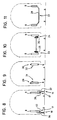
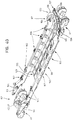
- the rail transport unit consists of a connecting support structure 1 having two front longitudinal ends 2 and rear 3, by which it is mounted directly or indirectly articulated on two blocks of railway axle (s) respectively front 4 and rear 5 via a suitable composite interface before 6 and rear 7.
- the supporting structure 1 has at least two pieces of parallel sides 8 and 9 ending at the front longitudinal 2 and rear 3 ends which are distinct or joined together.
- the composite interface 6 or 7 is integral with the corresponding axle block (x) 4 or 5.
- each axle block (s) 4 or 5 there must be between each axle block (s) 4 or 5 and the corresponding ends of the load-bearing connecting structure at least one articulation driving 10.
- the composite end interfaces 6 or 7 have, alone or simultaneously, at one of their ends, buffers such as 11 and a coupling hook 12 for shock absorption and transmission of the tensile force to axle block (s) or bogie (s).
- the carrying structure 1 is free at least at one of its longitudinal ends, for example rear 3, according to a partial or total access opening 13 but sufficient for the passage of the load or the road loading in the case of a loading by longitudinal or oblique penetration.
- At least the rear longitudinal end 3 free along the opening 13 is mounted separable from the adjacent axle block (x), at the front interface 6 by coupling-locking means.
- Such coupling-locking means may exist on the other front composite interface 7.
- At least one of the composite interfaces preferably the front composite interface 7, will have a loading / unloading pivot articulation 14 making it possible to rotate it as a whole.
- the two pivoting articulations, on the one hand for rolling 10, and on the other hand for loading / unloading 14, are juxtaposed or combined, or separate, but with the same axes.
- the present invention covers both two simple joints as well as a double joint of pivoting along a common axis.
- the link carrying structure can be separated from the two composite interfaces.
- the loading-pivoting articulation 14, possibly coincident with the rolling articulation 10 of one end of the carrying support structure 1, is common or has a common axis 15 with l 'articulation of loading-pivoting of the end of the immediately supporting link structure 1.
- the integrated lifting means 16 from one or the other end, or both, make it possible to create a vertical movement of clearance sufficient to carry out the dissociation of one or the other end, or both, of the adjacent axle block (s), or its associated composite interface structure.
- Means of lateral displacement for example of transverse rolling 17 on the ground, associated or not with the integrated lifting means 16, are intended to allow, in association with the lifting means, the disengagement of the carrying bearing structure by a vertical and then lateral movement in order to offset the transverse access opening 13 and to disengage it completely from the corresponding composite interface (FIGS. 8 and 12).
- the connecting support structure 1 is intended to carry various loads, in particular road loads that are wholly or partially formed.
- an articulated road assembly 18 vehicle carriers transporting cars such as 19 or a semi-trailer 20, or alternatively one or two ISO standardized containers or swap bodies 21 and 22, fixed on their roadside base or supported in different ways, for example at their classic corner pieces.
- the road load is carried by different means.
- these lower support structures are produced in the form of displacement means along tracks 25 and 26 of rolling, sliding or guiding, for the wheels or of rolling elements additional to the wheels (FIG. 10), or for mobile transverse mobile carrying structures accommodating the wheels or wheel sets of the road load to carry. It can be, for example, in the latter case, trolleys or mobile cradles along the above paths (not shown).
- the support carrying structure has a bottom 27, for example flat, in the form of a plate 28 joining the lower edges of each of the side pieces 8 and 9, in order to form an access ramp and a load-bearing plan for the road load (figure 11).
- the bottom 27 also constituting the access ramp is the load-bearing plane and is located at a level known as lowered.
- the rail transport unit can be opened or covered, and in the latter case, have a fixed or removable cover.
- support means for example consoles, fixed or erasable, upper 29.30 or lateral 31.32 equipped with twistlocks for the support of one or two containers or swap bodies by their corner pieces , these being susceptible of loading or unloading by a vertical movement of installation or removal (figure 9).
- the two flank pieces 8 and 9 of the connecting support structure 1 extend longitudinally beyond each of their ends by parallel extensions in the form of arms such as 33 and 34, for example rectilinear , coming in bearing relation with the corresponding composite interface mounted on its axle block (x) or bogie (s) ( Figures 12 to 28).
- the ends of the front and rear flank pieces are, for example, connected to each other by a front and rear connecting cross member such as 35 and 36 (FIGS. 12 to 28).
- the sidewall parts 8 and 9 can each be fitted along their internal face with a rolling, sliding or guide path, intended to serve as a movement support for the wheels of a vehicle, at a extension of the hub or to a carriage carrying a support accommodating the wheels of the road unit to be transported.
- the front end also comprises, at the rear ends of the side pieces, the integrated lifting means 16 in the form of extendable crutches 37, 38 with a support sole (FIGS. 8 and 12).
- the rolling means consist of lower rollers 39 and 40 shown diagrammatically in FIG. 12.
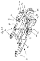
- the rail transport unit according to the invention can be mounted by each of its ends on a bogie 41 of the universal type, conventionally comprising a running gear, a carrying frame and a crapaudine 42 in which will come s' rotationally engaging a pivoting support 43 common to each of the connecting crosspieces 35 and 36 or two independent pivoting supports, crosspieces each carrying, at each of their ends, immobilization latch coupling means in two or three directions cooperating with suitable means.
- These crosspieces, pivoting connection are each provided to connect and support the ends of each of the arms bordering the front end as shown in Figures 13 to 28.
- a single pivot can be used to carry out, on the one hand the pivoting of rolling and in addition the pivoting function of loading / unloading of the immediately adjacent connection bearing structure in the case of articulations with common axis with that of the pivot of bogie.
- FIG. 4 This variant is already shown diagrammatically in FIG. 4 showing a common axle block (x) with a common interface and a common pivot axis.
- the wagon structure is a load-bearing structure meeting railway standards. It is intended to be coupled in a dissociable manner by one or the other of its ends on a bogie interface common to two successive adjacent structures and identical for all the bogies of the same convoy.
- the bogie interface is identical for all bogies of the same rail convoy.
- the invention aims, but is not limited to, the use of conventional and universal bogies.
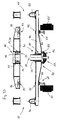
- the universal bogie 41 is traditionally composed of two axles 45 and 46 which, if necessary, carry brake discs, for example 47, 48, 49 and 50.
- the ends of the axles are mounted in rolling boxes 51, 52, 53 and 54 supporting twinning blocks 55 and 56 constituting with various other mechanical elements a chassis not shown in detail.
- This chassis supports at least one ball joint conventionally called crapaudine 57.
- This ball joint commonly receives pivotally the lower end structure of the wagon supported by the bogie.
- This common bogie interface adaptable to all common railway rolling bases called bogies makes it possible to articulate and simultaneously connect the front and rear ends of two successive wagon structures according to the invention on and by the same bogie.
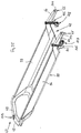
- This bogie interface is designed to serve as a common connecting piece for two successive wagon structures 60 and 61 of the same type in accordance with the present invention (FIGS. 36 to 38), for example removable and removable, comprising an open rear end 62 used for access to autonomous loading, for example the road unit.
- This rear end is bordered by two arms 63 and 64 similar to the arms 33 and 34 each terminated by a joining means 65, 66.
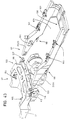
- the wagon structure also includes a front end 67 shaped as a "V" with two branches 68 and 69 converging along a point 70 which serves as a pivot center 71.
- the bogie interface in question is in the form of a pivoting interface crosspiece 72 mounted on the bogie 41 comprising a central articulated assembly 73 common to the two successive wagon structures 60 and 61.
- This crosspiece 72 comprises at each of its ends a receiving support, for example centering pins 74 and 75 or erasable or retractable means, for example retractable fingers which will be discussed later, for example conical, intended for receiving in a dissociable manner each of the arms 63 and 64 of the open rear end 62 of one of the wagon structures supported by the common bogie.
- These receiving supports are aligned with the center of the crosspiece. Beside these pins or associated with or integrated into them, additional locks are provided to ensure the safety of the coupling (not shown).
- These receiving supports constitute means of joining with complementary shapes provided at the ends 63 and 64 of the arms of the open rear end 62 of the wagon structure.
- the interface crosspiece 72 also has, on the underside, symmetrically on either side of each side of its articulated central assembly 73, a bearing surface for example in the form of attached plates 76, 77 opposite of each of the readers 58 and 59, these plates serving as a surface support and contact at the crosspiece 72.
- the interface cross-member 72 may have on its upper face on either side of its central part two friction-bearing plates 78 and 79 for two facing pads 80 and 81 mounted on springs 82 and 83 intended to make the abutment contact less brutal during roll movements and thereby ensure roll stability.
- the interface cross-member 72 rests on the bogie, on the one hand, in its center in an articulated manner, and on the other hand, laterally by its bearing pads on each of the sideboards thus offering the deflections according to the three degrees of freedom necessary between a wagon structure and a bogie.
- the articulated central assembly 73 proves to be complex.
- It comprises a lower articulation 84, mechanically carrying the cross member 72, lower articulation constituted by the clamp 57, that is to say a ball joint fitting into the receptacle of a semi-spherical lower body 85 existing on each bogie, ball joint that allows travel in all directions, that is to say according to the three degrees of freedom necessary between a wagon structure and its bogie.
- the central articulated assembly 73 also includes an upper articulation 86 resting or mounted on an element or a mechanical structure 87 integral with the cross-member 72 at the interface.
- This upper articulation 86 is coaxial with the lower articulation 84. These two articulations therefore have the same geometric axis 88.
- the upper articulation 86 receives, in a dissociable manner or not, the pivoting center 71 of the front end at a point 70 of the wagon structure constituting with it an articulation means.
- the upper articulation 86 allows at least the pivoting movements in a horizontal plane referred to in the loading / unloading mode using the lateral offset obliquely.
- this additional ball joint function to the pivoting function can be fulfilled simultaneously at the level of the upper articulation 86 as in the mixed upper articulation described below.
- the upper articulation 86 is a spherical bearing 89 mounted on a pivot cylinder 90 integral with the central part of the cross member and coaxial with the vertical pivot axis of the clamp.
- This spherical bearing develops around the pivot cylinder 90 and inside a cylindrical cage 91 with conical outer lateral surface 92 integral with or removable from the front end 67 at the tip of the wagon structure.
- the point 70 in "V" shape of the front end of the wagon structure is in the form of a simple through bore, either cylindrical or conical, coming to fit on the outside wall of the cage 91 of the spherical bearing.
- the example of bearing in question is a ball-and-socket bearing 93 on stepped rollers 94 and 95 arranged in a barrel giving it a biconical profile, as shown in FIGS. 32 and 33.
- the front end 67 of the wagon structure is mounted directly on the base plate while the interface cross-member 72 is articulated above on an extension, an axis crossing the end 67 or in any other way.
- the side pieces 96 and 97 extend rearwardly to a higher level by the two parallel arms 63 and 64, in the manner of a stretcher delimiting with the adjacent edges of the side pieces and the transverse end of the bottom l access opening 62 for the load.
- the side pieces 96 and 97 are extended forward by the two converging branches 68 and 69 arranged approximately at the same upper level as the arms 63 and 64 of the rear end 62. They have a general "V" shape, of which the point is directed forward in a median zone determined by the general median vertical plane of the wagon structure and an upper horizontal plane which may be that delimited by the two upper parallel edges of the flank pieces 96 and 97.
- the point 70 constituting the meeting of the two converging branches 68 and 69 is shaped so as to present an opening, for example an end bore 102 intended to allow it to be mounted in a dissociable manner or not, but preferably not dissociable, on the upper part of the double articulation 73.
- the rear end arms 63 and 64 62 are terminated by technical shapes which adapt to the end structures of the pivoting bogie interface crossmember to form the joining means 65 and 66.
- end cones or conical bores 103 and 104 which fit onto the centering pins that the interface crossmember has at each of its ends.
- the wagon structure When the end cones are fitted and locked, the wagon structure has a rigid transverse mechanical end connection constituted by the bogie interface crossmember.
- the retractable fingers 105, 106 present at both ends of the bogie interface are arranged in alignment with the central joint.
- end cones 103 and 104 each preceded, according to this variant, by an inclined ramp 111 and 112 with two successive penetration slopes at the entrance of an opening 113 and 114 for erasing back and the upward release during the longitudinal engagement and disengagement movements of the ends of the arms 63 and 64.
- This coupling connection can be blocked by additional end locks (not shown).
- the wagon structure optionally comprises, in the vicinity of its ends, individual lifting means possibly with integrated or non-integrated rolling, preferably autonomous, for example a crutch 115,116 similar to crutches 37 and 38 at each end of each piece of sidewalls 96 and 97 ( Figure 35) and this at one end of the wagon structure or at both ends at the same time.
- individual lifting means possibly with integrated or non-integrated rolling, preferably autonomous, for example a crutch 115,116 similar to crutches 37 and 38 at each end of each piece of sidewalls 96 and 97 ( Figure 35) and this at one end of the wagon structure or at both ends at the same time.
- crutches targeted is that of a retractable and extendable crutch, for example telescopic, manual or hydraulic.
- each stand 115 and 116 is fitted with rolling means such as 117 and 118 with a directional or fixed axis.
- the constant general direction of the latter is radial, that is to say passing through the pivot center 71.
- initial guide means are provided above the side pieces 96 and 97, at the arms of the rear end.
- rollers such as 119 and 120 with a vertical axis intended to ensure the centering and then the guiding of the load along its sides, for example along the lower edges 121, 122 of a body of a semi trailer 123 (figure 39).
- integrated means of securing for the load are provided: semi-trailer, container, swap body, etc., for example in the form of support on the arms or the upper or lateral edges of the side pieces.
- the fixing is carried out by conventional means, for example standard or non-standard twistlocks.
- the association and dissociation of the successive wagon structures with the single bogie interface is effected by fitting or disengaging the junction means at the rear and possibly the articulation means at the front.
- the conical bores 103 and 104 presented by the ends of the arms 63 and 64 of the rear end 62 of the wagon structure come to fit on the end centering pins of the cross member 72 of interface with closing of the latches additional or disengage from them by simple vertical movements or without requiring the slightest lifting in the case of retractable fingers.
- the front end of the wagon structure carrying the spherical bearing is mounted on the pivot cylinder 90 or disengaged from it in the case of a detachable variant according to which the central conical opening of the front end or bore can just as easily come to be mounted on the conical bearing head or extract from it by simple vertical movements.
- the means for locking the connection with the adjacent wagon structure consists of an erasable transverse finger provided at each end of the pivoting cross member and of a reception and extraction mechanism existing at each. the ends of the arms of the stretcher of the adjacent wagon structure.
- the two arms 20 and 21 or 63, 64 which border the rear end of the wagon structure are each terminated by a joining means with a transverse immobilization mechanism.
- the front end 67 shaped as a "V" with two branches 68 and 69 is pivotally mounted by its tip on the articulated central assembly 73 which is a pivoting assembly with a common geometric axis 88 with the pivoting axis of the pivoting cross member and that of the clamp 42.57 when it is in its vertical position.
- the articulated assembly 73 performs the pivoting connection between the clamp 57, a particular pivoting cross member 130 and the front end 67. It is similar to that already described for the previous variant with centering pins because it also has, as shown Figure 44, a pivot cylinder 131 around which is mounted an inner pivot joint 132 by which the cross member 130 is articulated.
- the pivoting cross member 130 is mechanically integrated into the front end 67 which is doubled and referenced 133, namely that this front end is made of two spaced parallel plates 134 and 135 kept spaced from each other by a spacer 136 and namely that the pivoting cross member 130 is itself pivotally mounted on the articulated assembly 73, and is housed in the space existing between the two plates of the front end 133 ( Figures 41 and 44) .
- the pivoting cross-member 130 therefore remains mechanically free, in particular in independent pivoting movements, but is sandwiched between the two plates 134 and 135 of the front end 67.
- the two spaced parallel plates 134 and 135 forming the front end 133 in "V" shape are secured to the pivot cylinder 131, itself secured to the clamp 57 of the bogie. Furthermore, the pivoting cross member 130 is pivotally mounted on the pivot cylinder 131 by means of the interior articulation 132.
- This internal articulation is preferably of the simple rolling or rolling type with ball-joint effect in order to allow small deflections in inclination such as those caused by the movements of roll or pitch.
- the pivoting cross member 130 includes at each of its ends a receiving support 137 and 138 making it possible to establish, maintain and dissociate the junction between its ends and the ends of the arms 63, 64 of the neighboring stretcher, c ' that is to say the connection with the preceding or following adjacent wagon structure.
- Each receiving support is shaped according to a cradle 139 and 140 or a folded sheet metal housing such as 141 ( Figure 46) in each of which emerges a transverse immobilization finger such as 142 mounted movable transversely and in elastic return to its extended position.
- Each cradle or housing more precisely affects the general shape of a gutter with converging lower inclined ramps 143 and converging lateral 144 and 145.
- the raising or lowering of the open end of the wagon structure is ensured by the crutches 115, 116 preferably hydraulic mounted on the arms of the stretcher.
- the doubled front end 133 is made vertically separable from the articulated assembly 73.
- the front end 133 is formed of a single plate above the pivoting cross member and can therefore dissociate vertically from the bogie.
- the pivoting cross member is completely independent since it is not sandwiched and the loading / unloading by vertical dissociation applies fully.
- the reception-immobilization means consist of reception supports 137 and 138 and transverse immobilization fingers such as 142 movable transversely between a retracted position and an extended position towards which they are constrained by a return spring. .
- Each immobilizing finger 142 may have a cylindrical body 146 sliding in a cylindrical housing 147 and a head 148 with two chamfers 149 and 150, for example slightly inclined, as shown in FIG. 46.
- the joining means relate to the converging form such as 153 for engagement with centering-guiding the ends of each arm 63 and 64 of the stretcher: for example that shown in FIG. 45.
- an engagement-extraction mechanism such as 154 visible in FIGS. 45 and 47.
- the rocker comprises a bent pivoting release piece 159 articulated on the one hand to a pivot axis 160 and on the other hand at the end of the connecting rod 158 by a side plate 161.
- the wagon structure optionally comprises in the vicinity of its ends individual lifting means possibly with integrated rolling means or no, preferably autonomous, by example the crutches 115, 116 provided at each end of each flank piece and this at one end of the wagon structure or at both ends simultaneously.
- the lifting means allow coupling and uncoupling without means of external handling of the wagon structure.
- twistlocks such as 162 and 163 cooperating with the lower corner pieces & have the containers fitted for their attachment to the wagon structure.
- end twist locks are provided, two at the front such as 164 and two at the rear such as 165. These end twist locks are supported by a retractable plate which allows to erase the assembly inside the wall of each of the ends of each flank piece.
- the loading / unloading phases are identical to those existing for the previous variants although this variant is more particularly oriented towards loading / unloading obliquely or in line.
- This variant makes it possible to avoid the multiple pre-centering adjustments necessary with the version with vertical centering pins.
- the height is automatically adjusted and centering-guidance is ensured by the entry ramps provided at the ends of the receiving supports.
- This overall lifting makes it possible to extract as a whole and with its load the rail transport unit from the convoy, to deposit it elsewhere on standby, or to insert it with its load in another rail convoy.
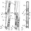
- Figures 13 to 16 show the structure loaded by a semi-trailer separated from the convoy by lifting using a crane or a gantry crane.
- the second mode concerns line / longitudinal loading / unloading ( Figures 17 to 22). The movements are indicated by arrows.
- This loading / unloading mode requires a loading area with rails integrated into the ground.
- the rail transport unit is joined or separated by a vertical lifting or translating movement or the two combined with its open transverse end, joining-decoupling movement provided by the integrated lifting means, for example the extendable crutches for support and / or by external means.
- the separation makes it possible to release the axle block (x) or bogie on the interface of which the ends of the side pieces were mounted.
- the road unit is loaded or unloaded, either directly along the linear load-bearing structures integrated in the wagon, or indirectly, via one or more transverse mobile load-bearing structures (s) ( s) along the wagon structure on which the undercarriage of the road unit rests.
- This road unit is coupled or secured or vice versa to an engine assembly 44, in view of its supply or evacuation in line on the platform, in the general direction of the railway convoy.
- a rear end having a deep and remote opening allows the engine assembly 44 to remain on the ground during maneuvers of bringing in or taking back the semi-trailer.
- Loading / unloading is carried out by bringing the front end obliquely after separation from the axle block (x) or front bogie by any means, for example by crutches, then offset obliquely by rolling on the quay loading, operation during which the carrying structure pivots as a whole around its rear end while taking pivoting rest on the axle block (x) or rear bogie.
- the wagon structure is lowered until the loading end touches the ground.
- the undercarriage of the road unit to be loaded is carried by the internal load-bearing linear structures 23 and 24 or mounted on the transverse load-bearing structures, cradles or carriages.
- the movement along the side pieces 8 and 9 or 96 and 97, towards or from its transport position, is ensured by integrated motor means or preferably by the road motor vehicle.
- the supporting structure is then moved laterally towards the axle block (x) or bogie by an overall pivoting movement in the same way as above, but in reverse order.
- Lifting means for example integrated in the form of crutches, raise the front ends of the side pieces, and come to place them opposite the securing-locking means provided on the interface of the axle block (x) or bogie.
- the supporting structure After coupling and locking, the supporting structure is ready in the convoy with its new load for rail transport.
- Means for lifting the rear end integrated into the wagon or exterior structure will, after opening additional latches, separate the joining means and obtain the dissociation of the wagon structure from the bogie interface.
- a rotational movement around the front end will ensure the clearance of the rear end by an oblique offset.
- Lifting means at both ends will allow the wagon structure to be removed by transverse or longitudinal offset.
- the means described above will offer the possibility of choosing and carrying out the loading / unloading mode best suited to the load (container, road unit or other) and to the configuration of the handling area of the station, train and the constraints and particularities of the sorting operation.
Applications Claiming Priority (6)
| Application Number | Priority Date | Filing Date | Title |
|---|---|---|---|
| FR9110590A FR2680492B1 (fr) | 1991-08-21 | 1991-08-21 | Unite de transport ferroviaire porteuse d'une charge routiere. |
| FR9110590 | 1991-08-21 | ||
| FR9202763A FR2688180B1 (fr) | 1992-03-04 | 1992-03-04 | Interface pivotante unique entre un bogie commun et deux structures wagon adjacentes. |
| FR9202764A FR2688179B1 (fr) | 1992-03-04 | 1992-03-04 | Structure wagon deposable articulee a une interface de bogie commune a deux structures adjacentes. |
| FR9202763 | 1992-03-04 | ||
| FR9202764 | 1992-03-04 |
Publications (2)
| Publication Number | Publication Date |
|---|---|
| EP0528741A1 true EP0528741A1 (de) | 1993-02-24 |
| EP0528741B1 EP0528741B1 (de) | 1998-07-08 |
Family
ID=27252502
Family Applications (1)
| Application Number | Title | Priority Date | Filing Date |
|---|---|---|---|
| EP92440097A Expired - Lifetime EP0528741B1 (de) | 1991-08-21 | 1992-08-21 | Trennbare Güterzugeinheit, insbesondere für den Transport von Strassenfahrzeugen |
Country Status (7)
| Country | Link |
|---|---|
| US (1) | US6095055A (de) |
| EP (1) | EP0528741B1 (de) |
| AT (1) | ATE168083T1 (de) |
| AU (1) | AU670756B2 (de) |
| CA (1) | CA2116006A1 (de) |
| DE (1) | DE69226138T2 (de) |
| WO (1) | WO1993003945A1 (de) |
Cited By (3)
| Publication number | Priority date | Publication date | Assignee | Title |
|---|---|---|---|---|
| WO1996011829A1 (en) * | 1994-10-18 | 1996-04-25 | Lars Berglund | A method and device for loading and unloading a goods train |
| WO1996037396A1 (en) * | 1995-05-26 | 1996-11-28 | Jan Eriksson | Railway waggon |
| EP0768226A2 (de) * | 1995-10-04 | 1997-04-16 | Matthias Gradenwitz | Cargosystem mit Rotationsbrücken zum Be- und Entladen von grossvolumigen Frachtgut, insbesondere Kraftfahrzeugen auf Eisenbahnzügen |
Families Citing this family (12)
| Publication number | Priority date | Publication date | Assignee | Title |
|---|---|---|---|---|
| JP2001522758A (ja) * | 1997-11-05 | 2001-11-20 | ダイムラークライスラー アーゲー | 鉄道車両システム |
| DE10104005A1 (de) * | 2001-01-31 | 2002-08-01 | Werner Haag | Verfahren und Niederflurfahrzeug zum Transport von Strassenfahrzeugen auf der Schiene |
| US6546878B1 (en) | 2001-10-12 | 2003-04-15 | Gunderson, Inc. | Multi-unit railroad freight car for carrying cargo containers |
| US6510800B1 (en) | 2001-10-12 | 2003-01-28 | Gunderson, Inc. | Multi-unit railroad freight car for carrying cargo containers between container well units |
| US20090151596A1 (en) * | 2007-12-12 | 2009-06-18 | William Harvey Sproat | Fastload rail carrier for motor vehicles, freight and passengers |
| US7757610B2 (en) | 2008-07-30 | 2010-07-20 | Gunderson Llc | Shortened container well |
| WO2010120236A1 (en) | 2009-04-16 | 2010-10-21 | K Technology Ab | A railway wagon and a method of its loading |
| US8616564B2 (en) * | 2009-12-07 | 2013-12-31 | Paceco Corp. | Cargo container handling cart and system using same |
| US8291592B2 (en) * | 2010-03-17 | 2012-10-23 | Gunderson Llc | Method of lengthening a container well of a railcar |
| US8177461B2 (en) | 2010-04-09 | 2012-05-15 | Gunderson Llc | Transport and storage of wheelsets |
| CN104494612A (zh) * | 2015-01-05 | 2015-04-08 | 齐齐哈尔轨道交通装备有限责任公司 | 铁路货车 |
| PL237854B1 (pl) * | 2018-03-15 | 2021-06-14 | Inst Pojazdow Szynowych Tabor | Wagon, zwłaszcza do transportu kombinowanego kolejowego- -drogowego |
Citations (5)
| Publication number | Priority date | Publication date | Assignee | Title |
|---|---|---|---|---|
| DE3234374A1 (de) * | 1982-09-16 | 1984-03-22 | Waggonfabrik Talbot, 5100 Aachen | Eisenbahn-gueterwagen zum transport von strassenfahrzeugen |
| EP0293359A1 (de) * | 1987-05-14 | 1988-11-30 | Austria Metall Aktiengesellschaft | Höhenverstellbarer Tiefladewaggon für Huckepackverkehr |
| WO1989005253A1 (fr) * | 1987-12-11 | 1989-06-15 | Intermotra | Dispositifs de transport de marchandises transformables en wagons et boggies ferroviaires pour cet usage |
| EP0403021A1 (de) * | 1989-06-13 | 1990-12-19 | Stork Alpha Engineering B.V. | Eisenbahnsystem und Drehgestell, Endwagen, Fahrzeugrahmen, Stützelement und Anhänger dafür |
| EP0465277A1 (de) * | 1990-06-29 | 1992-01-08 | USINES ET ACIERIES DE SAMBRE ET MEUSE Société Anonyme | Schiene- und Strasse-Transportsystem für Anhänger oder Behälter |
Family Cites Families (5)
| Publication number | Priority date | Publication date | Assignee | Title |
|---|---|---|---|---|
| US2246543A (en) * | 1938-11-28 | 1941-06-24 | Jay C Smith | Railroad car for transporting vehicles |
| US4653966A (en) * | 1986-01-08 | 1987-03-31 | Trailer Rail Partners | Drop-deck intermodal bogie |
| US5216956A (en) * | 1990-10-12 | 1993-06-08 | Adams Jr George W | Truck train system having a removable first truck and a second truck with a load platform and an extendable center sill |
| US5222443A (en) * | 1992-05-13 | 1993-06-29 | Knorr Brake Holding Corporation | Railway ramp car |
| FR2694913B1 (fr) * | 1992-08-20 | 1994-09-23 | Lohr Ind | Ensemble d'accouplement entre deux structures wagon successives et un bogie commun. |
-
1992
- 1992-08-21 AU AU25043/92A patent/AU670756B2/en not_active Ceased
- 1992-08-21 AT AT92440097T patent/ATE168083T1/de not_active IP Right Cessation
- 1992-08-21 EP EP92440097A patent/EP0528741B1/de not_active Expired - Lifetime
- 1992-08-21 DE DE69226138T patent/DE69226138T2/de not_active Expired - Lifetime
- 1992-08-21 CA CA002116006A patent/CA2116006A1/fr not_active Abandoned
- 1992-08-21 US US08/193,203 patent/US6095055A/en not_active Expired - Fee Related
- 1992-08-21 WO PCT/FR1992/000816 patent/WO1993003945A1/fr active Application Filing
Patent Citations (5)
| Publication number | Priority date | Publication date | Assignee | Title |
|---|---|---|---|---|
| DE3234374A1 (de) * | 1982-09-16 | 1984-03-22 | Waggonfabrik Talbot, 5100 Aachen | Eisenbahn-gueterwagen zum transport von strassenfahrzeugen |
| EP0293359A1 (de) * | 1987-05-14 | 1988-11-30 | Austria Metall Aktiengesellschaft | Höhenverstellbarer Tiefladewaggon für Huckepackverkehr |
| WO1989005253A1 (fr) * | 1987-12-11 | 1989-06-15 | Intermotra | Dispositifs de transport de marchandises transformables en wagons et boggies ferroviaires pour cet usage |
| EP0403021A1 (de) * | 1989-06-13 | 1990-12-19 | Stork Alpha Engineering B.V. | Eisenbahnsystem und Drehgestell, Endwagen, Fahrzeugrahmen, Stützelement und Anhänger dafür |
| EP0465277A1 (de) * | 1990-06-29 | 1992-01-08 | USINES ET ACIERIES DE SAMBRE ET MEUSE Société Anonyme | Schiene- und Strasse-Transportsystem für Anhänger oder Behälter |
Cited By (6)
| Publication number | Priority date | Publication date | Assignee | Title |
|---|---|---|---|---|
| WO1996011829A1 (en) * | 1994-10-18 | 1996-04-25 | Lars Berglund | A method and device for loading and unloading a goods train |
| WO1996037396A1 (en) * | 1995-05-26 | 1996-11-28 | Jan Eriksson | Railway waggon |
| US5988073A (en) * | 1995-05-26 | 1999-11-23 | Eriksson; Jan | Railway waggon |
| CN1077525C (zh) * | 1995-05-26 | 2002-01-09 | 扬·埃里克森 | 车皮 |
| EP0768226A2 (de) * | 1995-10-04 | 1997-04-16 | Matthias Gradenwitz | Cargosystem mit Rotationsbrücken zum Be- und Entladen von grossvolumigen Frachtgut, insbesondere Kraftfahrzeugen auf Eisenbahnzügen |
| EP0768226A3 (de) * | 1995-10-04 | 1998-07-29 | Matthias Gradenwitz | Cargosystem mit Rotationsbrücken zum Be- und Entladen von grossvolumigen Frachtgut, insbesondere Kraftfahrzeugen auf Eisenbahnzügen |
Also Published As
| Publication number | Publication date |
|---|---|
| CA2116006A1 (fr) | 1993-03-04 |
| AU2504392A (en) | 1993-03-16 |
| DE69226138D1 (de) | 1998-08-13 |
| ATE168083T1 (de) | 1998-07-15 |
| DE69226138T2 (de) | 1999-02-18 |
| WO1993003945A1 (fr) | 1993-03-04 |
| US6095055A (en) | 2000-08-01 |
| AU670756B2 (en) | 1996-08-01 |
| EP0528741B1 (de) | 1998-07-08 |
Similar Documents
| Publication | Publication Date | Title |
|---|---|---|
| EP2598392B1 (de) | Universelles system für laden/entladen und schienentransport für sattelanhänger | |
| EP0584026B1 (de) | Kupplungseinheit zwischen zwei aufeinander folgenden Waggons und einem gemeinsamen Drehgestell | |
| EP0320420B1 (de) | In Eisenbahnwagen umwandelbare Fahrzeuge und Transportvorrichtungen und Drehgestelle dafür | |
| EP0528741B1 (de) | Trennbare Güterzugeinheit, insbesondere für den Transport von Strassenfahrzeugen | |
| EP1292476B1 (de) | Transport- und scrägverladesystem für waggons in einem bahnhof für den kombinierten schienen-/strassen- transport und zugehöriges verfahren | |
| EP0781215B1 (de) | Sattelauflieger, insbesondere zum transport von fahrzeugen und verfahren für sein verladen auf fahrzeuge und sein entladen von fahrzeugen | |
| WO2002055359A1 (fr) | Unite ferroviaire a structure porteuse pivotante pour le transport combine rail/route soit d'une semi-remorque soit de deux vehicules a moteur | |
| EP0672566B1 (de) | Verfahren und System zum Be- und Entladen von Waggons für den Transport von Strassenfahrzeugen sowie Ladewaggon hierfür | |
| EP0112778B1 (de) | Tragrahmen zum Aufnehmen eines Wagens oder Güterbehälters für Verwendung auf Strasse, Schiene und Wasser | |
| WO2006072684A1 (fr) | Chariot d'atelier | |
| EP0905001A1 (de) | System für den Transport, die Ver- und Entladung von Strassenfahrzeugen, Containern oder anderen Gütern auf/von Waggons und Waggons hierfür | |
| EP0032471B1 (de) | Demontierbarer Waggon für die technische Koordination des kombinierten Schienen- und Strassenverkehrs | |
| FR2724899A1 (fr) | Procede d'engagement-degagement d'une structure ferroviaire par rapport a un convoi a partir de la charge qu'elle porte | |
| FR2624445A1 (fr) | Vehicules de transport mixte rail-route | |
| FR2680492A1 (fr) | Unite de transport ferroviaire porteuse d'une charge routiere. | |
| FR2938812A1 (fr) | Dispositif automatise de positionnement et de retrait d'un outillage de sellette | |
| FR2534870A1 (fr) | Semi-remorque pour la coordination technique rail-route et wagon charge de cette semi-remorque | |
| FR2666767A1 (fr) | Structure transversale d'extremite permettant la transformation rail-route d'une unite routiere. | |
| FR2482031A2 (fr) | Wagon demontable pour la coordination technique du transport rail-route | |
| CA2439548C (fr) | Systeme et methode de chargement et dechargement d'une plate forme pour vehicule routier | |
| FR2688179A1 (fr) | Structure wagon deposable articulee a une interface de bogie commune a deux structures adjacentes. | |
| FR2516029A1 (fr) | Dispositif pour le transport routier de wagons ferroviaires | |
| FR2688180A1 (fr) | Interface pivotante unique entre un bogie commun et deux structures wagon adjacentes. |
Legal Events
| Date | Code | Title | Description |
|---|---|---|---|
| PUAI | Public reference made under article 153(3) epc to a published international application that has entered the european phase |
Free format text: ORIGINAL CODE: 0009012 |
|
| AK | Designated contracting states |
Kind code of ref document: A1 Designated state(s): AT BE CH DE DK ES GB GR IT LI LU MC NL PT SE |
|
| 17P | Request for examination filed |
Effective date: 19930724 |
|
| R17P | Request for examination filed (corrected) |
Effective date: 19930816 |
|
| 17Q | First examination report despatched |
Effective date: 19950220 |
|
| GRAG | Despatch of communication of intention to grant |
Free format text: ORIGINAL CODE: EPIDOS AGRA |
|
| GRAG | Despatch of communication of intention to grant |
Free format text: ORIGINAL CODE: EPIDOS AGRA |
|
| GRAH | Despatch of communication of intention to grant a patent |
Free format text: ORIGINAL CODE: EPIDOS IGRA |
|
| GRAH | Despatch of communication of intention to grant a patent |
Free format text: ORIGINAL CODE: EPIDOS IGRA |
|
| GRAA | (expected) grant |
Free format text: ORIGINAL CODE: 0009210 |
|
| AK | Designated contracting states |
Kind code of ref document: B1 Designated state(s): AT BE CH DE DK ES GB GR IT LI LU MC NL PT SE |
|
| PG25 | Lapsed in a contracting state [announced via postgrant information from national office to epo] |
Ref country code: GR Free format text: LAPSE BECAUSE OF FAILURE TO SUBMIT A TRANSLATION OF THE DESCRIPTION OR TO PAY THE FEE WITHIN THE PRESCRIBED TIME-LIMIT Effective date: 19980708 Ref country code: ES Free format text: THE PATENT HAS BEEN ANNULLED BY A DECISION OF A NATIONAL AUTHORITY Effective date: 19980708 |
|
| REF | Corresponds to: |
Ref document number: 168083 Country of ref document: AT Date of ref document: 19980715 Kind code of ref document: T |
|
| REG | Reference to a national code |
Ref country code: CH Ref legal event code: EP |
|
| REF | Corresponds to: |
Ref document number: 69226138 Country of ref document: DE Date of ref document: 19980813 |
|
| PG25 | Lapsed in a contracting state [announced via postgrant information from national office to epo] |
Ref country code: PT Free format text: LAPSE BECAUSE OF FAILURE TO SUBMIT A TRANSLATION OF THE DESCRIPTION OR TO PAY THE FEE WITHIN THE PRESCRIBED TIME-LIMIT Effective date: 19981008 Ref country code: DK Free format text: LAPSE BECAUSE OF FAILURE TO SUBMIT A TRANSLATION OF THE DESCRIPTION OR TO PAY THE FEE WITHIN THE PRESCRIBED TIME-LIMIT Effective date: 19981008 |
|
| GBT | Gb: translation of ep patent filed (gb section 77(6)(a)/1977) |
Effective date: 19981008 |
|
| PG25 | Lapsed in a contracting state [announced via postgrant information from national office to epo] |
Ref country code: MC Free format text: LAPSE BECAUSE OF NON-PAYMENT OF DUE FEES Effective date: 19990228 |
|
| PLBE | No opposition filed within time limit |
Free format text: ORIGINAL CODE: 0009261 |
|
| STAA | Information on the status of an ep patent application or granted ep patent |
Free format text: STATUS: NO OPPOSITION FILED WITHIN TIME LIMIT |
|
| 26N | No opposition filed | ||
| PGFP | Annual fee paid to national office [announced via postgrant information from national office to epo] |
Ref country code: GB Payment date: 20010713 Year of fee payment: 10 |
|
| PGFP | Annual fee paid to national office [announced via postgrant information from national office to epo] |
Ref country code: BE Payment date: 20010717 Year of fee payment: 10 |
|
| PGFP | Annual fee paid to national office [announced via postgrant information from national office to epo] |
Ref country code: LU Payment date: 20010725 Year of fee payment: 10 |
|
| PGFP | Annual fee paid to national office [announced via postgrant information from national office to epo] |
Ref country code: SE Payment date: 20010823 Year of fee payment: 10 |
|
| PGFP | Annual fee paid to national office [announced via postgrant information from national office to epo] |
Ref country code: AT Payment date: 20010829 Year of fee payment: 10 |
|
| REG | Reference to a national code |
Ref country code: GB Ref legal event code: IF02 |
|
| PG25 | Lapsed in a contracting state [announced via postgrant information from national office to epo] |
Ref country code: LU Free format text: LAPSE BECAUSE OF NON-PAYMENT OF DUE FEES Effective date: 20020821 Ref country code: GB Free format text: LAPSE BECAUSE OF NON-PAYMENT OF DUE FEES Effective date: 20020821 Ref country code: AT Free format text: LAPSE BECAUSE OF NON-PAYMENT OF DUE FEES Effective date: 20020821 |
|
| PG25 | Lapsed in a contracting state [announced via postgrant information from national office to epo] |
Ref country code: SE Free format text: LAPSE BECAUSE OF NON-PAYMENT OF DUE FEES Effective date: 20020822 |
|
| PGFP | Annual fee paid to national office [announced via postgrant information from national office to epo] |
Ref country code: NL Payment date: 20020830 Year of fee payment: 11 |
|
| PG25 | Lapsed in a contracting state [announced via postgrant information from national office to epo] |
Ref country code: BE Free format text: LAPSE BECAUSE OF NON-PAYMENT OF DUE FEES Effective date: 20020831 |
|
| BERE | Be: lapsed |
Owner name: *LOHR INDUSTRIE Effective date: 20020831 |
|
| EUG | Se: european patent has lapsed | ||
| GBPC | Gb: european patent ceased through non-payment of renewal fee |
Effective date: 20020821 |
|
| PG25 | Lapsed in a contracting state [announced via postgrant information from national office to epo] |
Ref country code: NL Free format text: LAPSE BECAUSE OF NON-PAYMENT OF DUE FEES Effective date: 20040301 |
|
| NLV4 | Nl: lapsed or anulled due to non-payment of the annual fee |
Effective date: 20040301 |
|
| PGFP | Annual fee paid to national office [announced via postgrant information from national office to epo] |
Ref country code: CH Payment date: 20110711 Year of fee payment: 20 |
|
| PGFP | Annual fee paid to national office [announced via postgrant information from national office to epo] |
Ref country code: DE Payment date: 20110827 Year of fee payment: 20 |
|
| PGFP | Annual fee paid to national office [announced via postgrant information from national office to epo] |
Ref country code: IT Payment date: 20110825 Year of fee payment: 20 |
|
| REG | Reference to a national code |
Ref country code: DE Ref legal event code: R071 Ref document number: 69226138 Country of ref document: DE |
|
| REG | Reference to a national code |
Ref country code: DE Ref legal event code: R071 Ref document number: 69226138 Country of ref document: DE |
|
| REG | Reference to a national code |
Ref country code: CH Ref legal event code: PL |
|
| PG25 | Lapsed in a contracting state [announced via postgrant information from national office to epo] |
Ref country code: DE Free format text: LAPSE BECAUSE OF EXPIRATION OF PROTECTION Effective date: 20120822 |