EP0528741B1 - Separable freight train unit, particularly for the transport of road vehicles - Google Patents
Separable freight train unit, particularly for the transport of road vehicles Download PDFInfo
- Publication number
- EP0528741B1 EP0528741B1 EP92440097A EP92440097A EP0528741B1 EP 0528741 B1 EP0528741 B1 EP 0528741B1 EP 92440097 A EP92440097 A EP 92440097A EP 92440097 A EP92440097 A EP 92440097A EP 0528741 B1 EP0528741 B1 EP 0528741B1
- Authority
- EP
- European Patent Office
- Prior art keywords
- bogie
- transport unit
- unit according
- load
- loading
- Prior art date
- Legal status (The legal status is an assumption and is not a legal conclusion. Google has not performed a legal analysis and makes no representation as to the accuracy of the status listed.)
- Expired - Lifetime
Links
Images


Classifications
-
- B—PERFORMING OPERATIONS; TRANSPORTING
- B61—RAILWAYS
- B61D—BODY DETAILS OR KINDS OF RAILWAY VEHICLES
- B61D3/00—Wagons or vans
- B61D3/16—Wagons or vans adapted for carrying special loads
-
- B—PERFORMING OPERATIONS; TRANSPORTING
- B61—RAILWAYS
- B61D—BODY DETAILS OR KINDS OF RAILWAY VEHICLES
- B61D47/00—Loading or unloading devices combined with vehicles, e.g. loading platforms, doors convertible into loading and unloading ramps
Definitions
- the present invention relates to a unit of dissociable rail transport carrying a road loading consisting in particular of a unit road wholly or partially incorporated.
- This rail transport unit includes a load-bearing structure called a wagon structure resting on removably by either or both of its ends on two axle blocks (x) or bogies through interfaces.
- transverse receiving structures carry the undercarriage at the rear, while the pivot hitch is held in front by a support analog or constituting an equivalent of the support articulation classically called harness in articulated tractor-trailer combinations.
- the loading plan is specially raised to come to the level of the platform.
- the achievements according to this invention have the disadvantage of requiring a structure complex wagon, specially adapted for transhipment.
- Another disadvantage is the height of the loading plan whose access is not necessarily compatible with the level of the platform car.
- the object of the present invention is to alleviate the above disadvantages by proposing a structure carrier rail easy to manufacture, allowing fast loading / unloading operations and easy.
- the rail transport unit comprises a supporting structure connecting two axle blocks (x) or bogie (s) for the transport of a load or type load road, in particular a road unit totally or partially incorporated, and is particular in that the supporting structure is mounted on each of the blocks axle (s) or bogie (s) via a composite interface transmitting the forces of traction and shock, and in that at least one end of the supporting structure is open for delimit an access passage, said supporting structure being mounted directly or indirectly separable as a whole the interface of at least one block axle (s) or bogie (s) in order to fully release the passage of the load or the road loading for its access to or in the supporting structure through the opening access.
- axle block (s) or bogie (s) must be considered in the following as a rolling support any railroad, i.e. a set running on a railway track formed by at least one axle and a minimum load-bearing mechanical structure including the bearings. In the case of a two-axle unit, this structure includes the mechanical chassis connecting both axles.
- bogie The concept of bogie must be understood in this which follows as a rail rolling unit plus complete. It consists of an axle block (x) and various intermediate mechanical means ensuring the connection between the chassis of the wagon and said block axle (x).
- the intermediate mechanical means are called "interface”.
- the rail transport unit consists of a supporting structure of link 1 having two longitudinal ends front 2 and rear 3, by which it is located directly or indirectly mounted on two railway axle blocks (s) respectively before 4 and back 5 through an interface composite adapted before 6 and rear 7.
- the supporting structure 1 has at least two pieces of parallel sides 8 and 9 ending along the front 2 and rear longitudinal ends 3 separate or joined together.
- the interface composite 6 or 7 is integral with the axle block (x) corresponding 4 or 5.
- each axle block (x) 4 or 5 must be between each axle block (x) 4 or 5 and the corresponding ends of the supporting structure for connecting at least one articulation driving 10.
- Composite end interfaces 6 or 7 individually or simultaneously, with one of their ends, pads such as 11 and a hook hitch 12 for shock absorption and transmission of tensile force to the block axle (s) or bogie (s).
- the supporting structure 1 is free at least at one of its longitudinal ends, for example rear 3, according to a partial access opening 13 or total but sufficient for the passage of the load or of road loading in the case of loading by longitudinal or oblique penetration.
- Such coupling-locking means can exist on the other front composite interface 7.
- At least one of the composite interfaces of preferably the composite interface before 7, will present a loading / unloading pivot joint 14 allowing it to rotate in its together.
- the two pivot joints, on the one hand of rolling 10, and on the other hand loading / unloading 14, are juxtaposed or combined, or distinct, but with axes confused.
- the present invention covers two single joints than a double joint of pivoting along a common axis.
- the load-bearing connecting structure can be separated from the two composite interfaces.
- the loading-pivoting articulation 14, possibly confused with the rolling joint 10 from one end of the connecting support structure 1, is common or has a common axis 15 with the load-pivot joint at the end of the connecting support structure 1 immediately next.
- the integrated lifting means 16 of one or on the other end, or both create sufficient vertical release movement to realize the dissociation of one or the other end, or both, of the adjacent axle block (s), or its associated composite interface structure.
- Lateral displacement means for example of transverse running 17 on the ground, associated or not to the integrated lifting means 16, are intended to allow, in association with the lifting means, the dislocation of the load-bearing connecting structure by a vertical then lateral movement in order to decentralize the transverse access opening 13 and release it totally from the corresponding composite interface ( Figures 8 and 12).
- the loading / unloading modes in oblique and online are facilitated by aforementioned characteristics, concerning the opening transverse access 13 present at one of ends, for example rear, pivoting overall, but also the presence of structures linear carriers which will be discussed below.
- the supporting link structure 1 is intended to carry various loads, in particular road loads fully or partially incorporated.
- an articulated road assembly 18 vehicle carriers carrying cars such as 19 or a semi-trailer 20, or even one or more two standardized containers or swap bodies 21 and 22 ISO, fixed on their road base or supported by different ways, for example in terms of their classic corner pieces.
- the road load is carried by different means.
- linear internal carriers 23 and 24 present on along the side pieces 8 and 9 which hold the loading support plan at a level said lowered, i.e. below the upper level axle block (s) or bogie (s).
- these structures lower carriers are produced in the form of means of movement along paths 25 and 26 of bearing, sliding or guide, for wheels or additional rolling elements to the wheels (figure 10), or for mobile structures transverse movable carriers accommodating the wheels or the road load wheel trains at carry. It can be, for example, in this last case, trolleys or cradles movable along of the above paths (not shown).
- the structure link carrier has a bottom 27, for example flat, in the form of a plate 28 bringing together the lower edges of each of the flank pieces 8 and 9, to form an access ramp and a supporting plane for the road load (figure 11).
- the bottom 27 also constituting the access ramp is the plan load carrier and is located at a level said lowered.
- the rail transport unit can be opened or covered, and in this last case, present a fixed or removable cover.
- the two flank pieces 8 and 9 of the supporting structure of link 1 extend longitudinally beyond each of their ends by extensions arm-shaped parallels such as 33 and 34, by straight example, coming in support relation with the corresponding composite interface mounted on its axle block (s) or bogie (s) ( Figures 12 to 28).
- the ends of the front and rear flank pieces are, for example, interconnected by a front link cross member and rear such as 35 and 36 ( Figures 12 to 28).
- the side pieces 8 and 9 can be fitted each along their face internal of a raceway, sliding or guide, intended to serve as a movement support for wheels of a vehicle, to an extension of the hub or to a carriage carrying a support accommodating the wheels of the road unit to be transported.
- the front end further comprises at the level rear ends of the flank pieces, the means integrated lifting gear 16 in the form of crutches extensible 37.38 with support sole ( Figures 8 and 12).
- the rolling means consist of lower rollers 39 and 40 shown schematically in Figure 12.
- the rail transport unit according to the invention can be mounted at each of its ends on a bogie 41 of the universal type, conventionally comprising a running gear, a carrying frame and a crapaudine 42 in which will come s' rotationally engaging a pivoting support 43 common to each of the connecting crosspieces 35 and 36 or two independent pivoting supports, crosspieces each carrying, at each of their ends, immobilization latch coupling means in two or three directions cooperating with suitable means.
- These crosspieces, pivoting link are each provided to connect and support the ends of each of the arms bordering the front end as shown in Figures 13 to 28.
- a single pivot can be used to on the one hand, the rolling pivoting and plus the swivel function of loading / unloading of the load-bearing structure immediately neighboring link in the case articulations with a common axis with that of the pivot of bogie.
- the wagon structure is a load-bearing structure meeting railway standards. It is intended for come to mate in a dissociable way by one or the other of its ends on a bogie interface common to two successive adjacent structures and identical for all the bogies of the same convoy.
- Bogie interface is the same for everyone the bogies of the same rail convoy.
- the invention aims, but not limiting, the use of classic bogies and universal.
- the bogie universal 41 traditionally consists of two axles 45 and 46 which, if applicable, have brake discs, e.g. 47, 48, 49 and 50.
- This chassis supports at least one articulation patella conventionally called crapaudine 57.
- This ball joint commonly receives pivoting the lower end structure of the supported car by the bogie.
- This common bogie interface adaptable to all common railway rolling bases called bogies allows to articulate and connect simultaneously the front and rear ends of two successive wagon structures according to the invention on and by the same bogie.
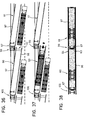
- This bogie interface is intended for serve as a common connecting piece for two structures successive wagons 60 and 61 of the same type in accordance with present invention ( Figures 36 to 38), for example removable and removable, comprising one end open rear 62 used for loading access autonomous, for example the road unit.
- This end rear is bordered by two arms 63 and 64 similar to arms 33 and 34 each terminated by a joining means 65, 66.
- the wagon structure also includes a front end 67 shaped like a "V" with two branches 68 and 69 converging along a point 70 which serves as pivot center 71.
- the bogie interface in question is present in the form of an interface crosspiece pivoting 72 mounted on the bogie 41 comprising a articulated central unit 73 common to the two structures successive wagons 60 and 61.
- This crosspiece 72 comprises at each of its ends a receiving support, for example centering pins 74 and 75 or erasable means or retractable, for example retractable fingers, it will be discussed later, for example of form conical, intended to receive in a dissociable way each of arms 63 and 64 of the open rear end 62 of one of the wagon structures supported by the bogie common.
- These receiving supports are aligned with the center of the sleeper. Next to these pawns or associates or integrated into them are provided locks additional to ensure coupling safety (not shown).
- reception supports constitute means of joining with complementary shapes provided at the ends 63 and 64 of the arms of the end open rear 62 of the wagon structure.
- the interface crosspiece 72 presented by elsewhere, on the underside, symmetrically in part and on either side of its articulated central assembly 73, a support area for example in the form of inserts 76, 77 opposite each of the reader 58 and 59, these plates serving as surface support and contact at the crosspiece 72.
- the interface cross member 72 can present on its upper side on either side of its central part two friction-bearing plates 78 and 79 for two pads opposite 80 and 81 mounted on springs 82 and 83 intended to make the contact support during roll movements and thereby even provide roll stability.
- the interface cross member 72 rests on the bogie, on the one hand, in its center in an articulated way, and on the other hand, laterally by its support surfaces on each of the sideboards thus offering the deflections according to the three degrees of freedom required between a wagon structure and a bogie.
- the articulated central assembly 73 turns out complex.
- the articulated central assembly 73 comprises also an upper articulation 86 resting or mounted on a mechanical element or structure 87 secured to the interface cross member 72.
- This upper articulation 86 is coaxial at the lower joint 84. These two joints therefore have the same geometric axis 88.
- the upper articulation 86 receives so separable or not the pivot center 71 of the front end at point 70 of the wagon structure constituting with it a means of articulation.
- the upper articulation 86 allows at least the pivoting movements in a horizontal plane referred to in the mode of loading / unloading using lateral offset in oblique.
- this ball joint function additional to the swivel function, can be filled simultaneously at the joint upper 86 as in the upper joint mixed described below.
- upper joint 86 is a spherical bearing 89 mounted on a pivot cylinder 90 secured to the central part of the cross member and coaxial with the axis vertical pivot of the basket.
- This spherical bearing develops around the pivot cylinder 90 and inside a cage 91 cylindrical with conical outer side surface 92 integral with or detachable from the front end 67 in tip of the wagon structure.
- the point 70 in "V" of the front end of the wagon structure is presented as a simple through bore, either cylindrical, either conical, coming to fit on the outer wall of the cage 91 of the spherical bearing.
- the front end 67 of the wagon structure is mounted directly on the when the interface cross member 72 is articulated above on an extension, an axis crossing end 67 or in any other way.
- Flank pieces 96 and 97 extend backward to a higher level by both arms parallel 63 and 64, like a stretcher delimiting with the adjacent edges flank pieces and the transverse end of the bottom the access opening 62 for the charge.
- the general conformation of the extremity rear 62 visible in the figures is such that the opening plan 101 thereof is located largely in withdrawal from the ends of arms 63 and 64.
- Flank pieces 96 and 97 extend forward by the two converging branches 68 and 69 arranged at approximately the same upper level as the arms 63 and 64 of the rear end 62. They have a general "V" shape whose tip is directed forward in a determined median zone by the general median vertical plane of the structure wagon and an upper horizontal plane which can be the one bounded by the two upper parallel edges flank pieces 96 and 97.
- the point 70 constituting the union of the two converging branches 68 and 69 is shaped so as to present an opening for example a bore end 102 intended to allow it to come mount in a dissociable way or not, but preferably not dissociable, on the upper part of the double joint 73.
- the rear end arms 63 and 64 62 are terminated by technical forms adapted to the end structures of the pivoting cross member bogie interface to form the joining means 65 and 66.
- the wagon structure When the end cones are fitted and locked, the wagon structure has a connection rigid transverse mechanical end incorporated by the bogie interface cross member.
- the 105,106 retractable fingers present at the two ends of the bogie interface are arranged in alignment with the central joint.
- end cones 103 and 104 each preceded, according to this variant, by a inclined ramp 111 and 112 on two successive slopes of penetration at the entrance of an opening 113 and 114 for backward erasure and upward release during the longitudinal movements of engagement and clearance of the ends of the arms 63 and 64.
- This coupling link can be blocked by additional end locks (not represented).
- the wagon structure has so optional near its ends of the means individual lifting possibly with rolling integrated or not, preferably autonomous, for example a crutch 115,116 similar to crutches 37 and 38 to each of the ends of each flank piece 96 and 97 (figure 35) and this at one end of the wagon structure or at both ends at the same time.
- a crutch 115,116 similar to crutches 37 and 38 to each of the ends of each flank piece 96 and 97 (figure 35) and this at one end of the wagon structure or at both ends at the same time.
- crutches targeted is that of a retractable and extendable stand for example telescopic, manual or hydraulic.
- each stand 115 and 116 of rolling means such as 117 and 118 with directional or fixed axis.
- Means can also be provided for bearings separated from the stands.
- means are provided for initial guidance over the side pieces 96 and 97, at the arms of the rear end.
- rollers such as 119 and 120 with vertical axis intended to ensure the centering then guiding the load along its flanks, for example along the lower edges 121,122 of the body of a 123 semi-trailer ( Figure 39).
- integrated means are provided load securing: semi-trailer, container, swap body etc ..., for example in the form of support on the upper or lateral arms or edges of flank pieces.
- the fixing is done by means conventional, for example twistlocks standardized or not.
- association and dissociation of successive wagon structures with the unique interface of bogie are carried out by nesting or dislocation of connecting means at the rear and possibly articulation means at the front.
- tapered bores 103 and 104 that have the ends of arms 63 and 64 of the rear end 62 of the wagon structure come fit onto the end centering pins of the crosspiece 72 interface with lock closure additional or get rid of them by simple vertical movements or without requiring the slightest lifting in the case of retractable fingers.
- the front end of the structure wagon carrying the spherical bearing is mounted on the pivot cylinder 90 or disengage from it in the case of a detachable variant according to which the conical central opening at the front end or bore can just as easily be mounted on the conical bearing head or extract from it by simple vertical movements.
- This overall lifting allows to extract in its whole and with its loading the unit of rail transport of the convoy, drop it off somewhere else pending, or insert it with its load in a another rail convoy.
- Figures 13 to 16 show the structure loaded by a semi-trailer separated from the convoy by lifting using a crane or gantry.
- the second mode concerns loading / unloading in line or longitudinal ( Figures 17 to 22). The movements are indicated by arrows.
- This loading / unloading mode requires a loading area called rails integrated in the ground.
- the transport unit rail is joined or separated by a vertical lifting or traveling movement or two handsets from its open cross end, solidarity-decoupling movement brought by the integrated lifting means, for example the extendable crutches for support and / or by means exteriors.
- the separation makes it possible to free the axle block (s) or bogie on whose interface the ends of the flank pieces were fitted.
- the road unit is loaded or unloaded, either directly along the load-bearing linear structures of displacement integrated into the Wagon, either indirectly, through one or more structure (s) transverse carrier (s) mobile (s) along the wagon structure on which or on which rests the undercarriage of the road unit.
- This road unit is coupled or secured or vice versa to a motor assembly 44, in view of its supply or evacuation in line on the quay, following the general direction of the convoy rail.
- a rear end having a deep and remote opening allows the whole engine 44 to stay on the ground during supply maneuvers or recovery of the semi-trailer.
- Loading / unloading takes place in bringing the front end oblique after detachment from the axle block (s) or bogie before by any means, for example by crutches, then offset obliquely by rolling on the quay loading, operation during which the structure carrier as a whole pivots around its rear end by pivoting support on the axle block (s) or rear bogie.
- the running gear of the unit road to be loaded is carried by the structures linear internal carriers 23 and 24 or mounted on transverse load-bearing structures, cradles or carts. Moving along the flank pieces 8 and 9 or 96 and 97, to or from its position of transport, is provided by integrated motor means or preferably by the road motor vehicle.
- the supporting structure is then moved laterally towards the axle block (x) or bogie by a overall pivoting movement in the same way as previously, but in reverse order.
- Lifting means for example integrated in the form of crutches, raise the front ends flank pieces, and come to place them opposite securing-locking means provided on the interface of the axle block (x) or bogie.
- the supporting structure After coupling and locking, the supporting structure is ready in the convoy with its re-loading for rail transport.
- Means for lifting the rear end integrated into the wagon or exterior structure will allow, after opening additional locks, to separate the joining means and obtain the dissociation of the wagon structure from the interface of bogie.
- a rotational movement around the end front will ensure the clearance of the rear end by an oblique offset.
- Lifting means at both ends allow the removal of the wagon structure by transverse or longitudinal shift.
- the means described above will provide the possibility to choose and carry out the loading / unloading best suited to the load (container, road unit or other) and at the configuration of the station handling area, train and constraints and peculiarities of the sorting operation.
Landscapes
- Engineering & Computer Science (AREA)
- Transportation (AREA)
- Mechanical Engineering (AREA)
- Handcart (AREA)
- Chain Conveyers (AREA)
- Loading Or Unloading Of Vehicles (AREA)
- Body Structure For Vehicles (AREA)
Abstract
Description
La présente invention se rapporte à une unité de transport ferroviaire dissociable porteuse d'un chargement routier consistant notamment en une unité routière totalement ou partiellement constituée.The present invention relates to a unit of dissociable rail transport carrying a road loading consisting in particular of a unit road wholly or partially incorporated.
Cette unité de transport ferroviaire comporte une structure porteuse dite structure wagon reposant de façon amovible par l'une et l'autre ou l'une ou l'autre de ses extrémités sur deux blocs d'essieu(x) ou bogies par l'intermédiaire d'interfaces.This rail transport unit includes a load-bearing structure called a wagon structure resting on removably by either or both of its ends on two axle blocks (x) or bogies through interfaces.
Elle permet le chargement rapide notamment d'une ou de plusieurs unités routières tractées, portées ou semi-portées, caisses mobiles, conteneurs ou autres.It allows fast loading in particular one or more towed road units, carried or semi-carried, swap bodies, containers or other.
On connaít le transport des conteneurs et des semi-remorques sur des structures porteuses ferroviaires reliant deux blocs d'essieu(x) ou bogie(s).We know the transport of containers and semi-trailers on load-bearing structures railway connecting two axle blocks (x) or bogie (s).
D'abord, en ce qui concerne les conteneurs, ils sont arrimés sur ces structures par l'intermédiaire de leurs pièces de coin normalisées ISO sur des supports latéraux saillants portant chacun un verrou tournant.First, with regard to containers, they are secured to these structures via of their ISO standard corner pieces on protruding side supports each carrying a lock turning.
Ces conteneurs sont chargés et déchargés à l'aide de pinces portées et mises en oeuvre par des grues, portiques, engins roulants tels qu'élévateurs ou autres moyens de manutention.These containers are loaded and unloaded at by means of pliers carried and implemented by cranes, gantries, rolling machines such as elevators or other means of handling.
Concernant les remorques et semi-remorques, des structures réceptrices transversales portent le train roulant à l'arrière, alors que le pivot d'attelage est maintenu à l'avant par un support analogue ou constituant un équivalent du support d'articulation appelé classiquement sellette dans les ensembles routiers articulés à semi-remorque.Regarding trailers and semi-trailers, transverse receiving structures carry the undercarriage at the rear, while the pivot hitch is held in front by a support analog or constituting an equivalent of the support articulation classically called harness in articulated tractor-trailer combinations.
Si le maintien de la charge est correctement assuré, la mise en oeuvre des opérations de chargement et de déchargement ne s'avère guère aisée en raison des moyens lourds utilisés et de la relative précision de coïncidence à observer pour l'arrimage.If the charge is maintained correctly assured, the implementation of loading operations and unloading is not very easy due to the heavy means used and the relative precision of coincidence to observe for stowage.
On a également réalisé les opérations de chargement/déchargement par translation latérale d'une plate-forme de wagon entre un quai de chargement et une structure ferroviaire réceptrice ou wagon.We also carried out the operations of loading / unloading by lateral translation of a wagon platform between a loading dock and a receiving railway structure or wagon.
On peut citer à titre illustratif la structure wagon décrite dans le brevet allemand n° DE 3139220 dont les deux extrémités de la plate-forme sont des coulisses latérales par rapport aux blocs d'essieu(x) ou bogie(s).We can cite by way of illustration the wagon structure described in German patent n ° DE 3139220 with both ends of the platform side slides in relation to the blocks axle (s) or bogie (s).
Pour amener cette structure wagon dans sa position de chargement ou de déchargement, il est nécessaire de l'arrêter le long d'un plan de chargement extérieur spécialement aménagé, puis de translater la plate-forme transversalement au châssis, et de la faire reposer sur le plan de chargement.To bring this wagon structure into its loading or unloading position it is necessary to stop it along a loading plan specially landscaped exterior, then translate the platform transversely to the chassis, and make it rest on the loading surface.
Selon cette invention, le plan de chargement est spécialement surélevé pour venir au niveau de la plate-forme.According to this invention, the loading plan is specially raised to come to the level of the platform.
Selon cette invention également, seule la plate-forme porteuse est déplacée, et non la totalité de la structure.According to this invention also, only the carrier platform is moved, not all of the structure.
Les réalisations conformes à cette invention présentent l'inconvénient de nécessiter une structure wagon complexe, spécialement adaptée au transbordement.The achievements according to this invention have the disadvantage of requiring a structure complex wagon, specially adapted for transhipment.
Ces moyens onéreux et non universels ne conviennent pas à tous les types de charges.These expensive and non-universal means do not not suitable for all types of loads.
Un autre inconvénient réside dans la hauteur du plan de chargement dont l'accès n'est pas nécessairement compatible avec le niveau de la plate-forme wagon.Another disadvantage is the height of the loading plan whose access is not necessarily compatible with the level of the platform car.
La présente invention a pour but de pallier les inconvénients ci-dessus en proposant une structure ferroviaire porteuse facile à fabriquer, permettant des opérations de chargement/déchargement rapides et aisées.The object of the present invention is to alleviate the above disadvantages by proposing a structure carrier rail easy to manufacture, allowing fast loading / unloading operations and easy.
De plus, en vue de faciliter le désaccouplement et la mise en place du chargement en position désalignée, on prévoit de l'équiper, au moins à l'une de ses extrémités, d'un moyen de levage associé à des moyens de roulement en vue d'un déplacement latéral par pivotement autour de l'extrémité opposée.In addition, in order to facilitate uncoupling and placing the load in position misaligned, we plan to equip it, at least in one of its ends, of a lifting means associated with rolling means for lateral movement by pivot around the opposite end.
A cet effet, l'unité de transport ferroviaire selon l'invention comprend une structure porteuse reliant deux blocs d'essieu(x) ou bogie(s) pour le transport d'une charge ou d'un chargement de type routier, notamment une unité routière totalement ou partiellement constituée, et se particularise en ce que la structure porteuse est montée sur chacun des blocs d'essieu(x) ou bogie(s) par l'intermédiaire d'une interface composite transmettant les efforts de traction et les chocs, et en ce qu'au moins une extrémité de la structure porteuse est ouverte pour délimiter un passage d'accès, ladite structure porteuse étant montée directement ou indirectement dissociable dans son ensemble de l'interface d'au moins un bloc d'essieu(x) ou bogie(s) en vue de dégager totalement le passage de la charge ou du chargement routier pour son accès sur ou dans la structure porteuse par l'ouverture d'accès.To this end, the rail transport unit according to the invention comprises a supporting structure connecting two axle blocks (x) or bogie (s) for the transport of a load or type load road, in particular a road unit totally or partially incorporated, and is particular in that the supporting structure is mounted on each of the blocks axle (s) or bogie (s) via a composite interface transmitting the forces of traction and shock, and in that at least one end of the supporting structure is open for delimit an access passage, said supporting structure being mounted directly or indirectly separable as a whole the interface of at least one block axle (s) or bogie (s) in order to fully release the passage of the load or the road loading for its access to or in the supporting structure through the opening access.
Les avantages de l'invention se montrent nombreux. On peut citer notamment :
- possibilité de déchargement même sur des quais ne comportant pas d'installation de manutention ;
- possibilité de chargement/déchargement quel que soit le niveau du quai ;
- rapidité des opérations de mise en oeuvre et de chargement/déchargement ;
- aptitude à recevoir tous types de chargement.
- possibility of unloading even on quays without a handling facility;
- possibility of loading / unloading whatever the level of the quay;
- speed of implementation and loading / unloading operations;
- ability to receive all types of cargo.
Par ailleurs, en raison du caractère dissociable de la structure porteuse selon l'invention, et en fonction du mode de réalisation particulier, à l'avant et à l'arrière, on peut envisager son enlèvement à l'état vide ou chargé, par le simple mouvement vertical d'un engin de levage extérieur, pour l'extraire d'un convoi ferroviaire, afin de l'insérer directement dans un autre convoi à proximité, ou de déposer la structure porteuse sur un quai en vue d'un chargement ou déchargement.Furthermore, due to the character separable from the supporting structure according to the invention, and depending on the particular embodiment, to front and rear, we can consider its removal in empty or loaded state, by simple vertical movement of an external lifting device, for extract it from a train convoy, in order to insert it directly in another convoy nearby, or deposit the supporting structure on a quay for a loading or unloading.
Les moyens spécifiques d'un mode de réalisation particulier lui permettent de viser deux autres façons de procéder aux opérations de chargement/déchargement : en ligne et en oblique. Cette dernière solution procure un gain de temps notable sur la durée totale de chargement d'un convoi ferroviaire.The specific means of a particular achievement allow him to target two other ways to do loading / unloading: online and oblique. This last solution saves significant time on the total loading time of a rail convoy.
On décrira ci-après plus en détail plusieurs modes de réalisation non limitatifs de la structure de wagon dissociable conforme à l'invention, en référence aux dessins accompagnants dans lesquels :
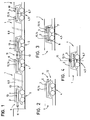
- la figure 1 est une vue schématique de profil d'une succession composite de plusieurs unités de transport ferroviaire ;
- les figures 2, 3 et 4 sont des vues schématiques de
profil montrant trois types d'extrémités de l'unité
routière selon l'invention, respectivement :
- avec tampon et crochet d'attelage sur l'interface,
- avec bloc d'essieu(x) ou bogie commun à deux extrémités,
- avec bloc d'essieu(x) ou bogie commun, interface commune et axe de pivotement commun ;
- les figures 5, 6 et 7 sont des vues de profil illustrant des exemples d'applications respectivement aux structures routières porte-voitures, à une remorque semi-portée et à des conteneurs ;
- la figure 8 est une vue en coupe transversale illustrant un des moyens de levage intégré sous la forme de béquilles avec représentation du gabarit en traits mixtes ;
- la figure 9 est une vue en coupe transversale montrant des structures de soutien d'un ou de plusieurs conteneurs avec représentation du gabarit en traits mixtes ;
- la figure 10 est une vue en coupe transversale illustrant les moyens de déplacement-soutien longitudinaux avec représentation du gabarit en traits mixtes ;
- la figure 11 est une vue en coupe transversale illustrant un exemple de réalisation à fond plat ;
- la figure 12 est une vue schématique en perspective de la structure porteuse vue d'une de ses extrémités dans sa version à fond plat ;
- les figures 13 à 16 sont des vues successives de profil, puis en plan, montrant le chargement/déchargement par levage ;
- les figures 17 à 22 sont des vues schématiques de profil illustrant une séquence de déchargement selon le mode en ligne ;
- les figures 23 à 28 sont des vues de profil puis en plan montrant les différentes phases d'une séquence de chargement selon le mode en oblique.
- la figure 29 est une vue générale en perspective de l'ensemble de la structure wagon selon l'invention ;
- la figure 30 est une vue en perspective de l'extrémité avant et de l'interface de bogie sur laquelle elle est montée ;
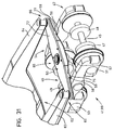
- la figure 31 est une vue en perspective de l'extrémité avant et de l'interface de bogie sur laquelle elle est destinée à être montée ;
- les figures 32 et 33 sont des vues en coupe longitudinale de la traverse avant et après dissociation ;
- la figure 34 est une vue en perspective de l'extrémité d'un des bras arrière coopérant avec un doigt rétractable ;
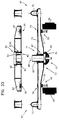
- la figure 35 est une vue simplifiée en perspective de la structure wagon montrant des moyens de levage vertical et de roulage latéral intégrés ;
- les figures 36, 37 et 38 sont des vues schématiques en plan illustrant un chargement en épi dans le cas d'une application à une unité routière du type semi-remorque ;
- la figure 39 est une vue simplifiée en élévation de l'arrière de la structure wagon chargée par une semi-remorque.
- Figure 1 is a schematic profile view of a composite succession of several rail transport units;
- Figures 2, 3 and 4 are schematic side views showing three types of ends of the road unit according to the invention, respectively:
- with buffer and towing hook on the interface,
- with axle block (x) or bogie common at both ends,
- with common axle block (s) or bogie, common interface and common pivot axis;
- Figures 5, 6 and 7 are side views illustrating examples of applications respectively to car transporter road structures, a semi-trailer and containers;
- Figure 8 is a cross-sectional view illustrating one of the integrated lifting means in the form of crutches with representation of the template in phantom;
- Figure 9 is a cross-sectional view showing support structures of one or more containers with representation of the template in phantom;
- Figure 10 is a cross-sectional view illustrating the longitudinal displacement-support means with representation of the template in phantom;
- Figure 11 is a cross-sectional view illustrating an embodiment with a flat bottom;
- Figure 12 is a schematic perspective view of the support structure seen from one of its ends in its flat bottom version;
- Figures 13 to 16 are successive side views, then in plan, showing loading / unloading by lifting;
- Figures 17 to 22 are schematic side views illustrating an unloading sequence according to the online mode;
- Figures 23 to 28 are side views then in plan showing the different phases of a loading sequence according to the oblique mode.
- Figure 29 is a general perspective view of the entire wagon structure according to the invention;
- Figure 30 is a perspective view of the front end and the bogie interface on which it is mounted;
- FIG. 31 is a perspective view of the front end and of the bogie interface on which it is intended to be mounted;
- Figures 32 and 33 are views in longitudinal section of the cross member before and after dissociation;
- Figure 34 is a perspective view of the end of one of the rear arms cooperating with a retractable finger;
- FIG. 35 is a simplified perspective view of the wagon structure showing integrated vertical lifting and lateral rolling means;
- Figures 36, 37 and 38 are schematic plan views illustrating a spike loading in the case of an application to a road unit of the semi-trailer type;
- FIG. 39 is a simplified view in elevation of the rear of the wagon structure loaded by a semi-trailer.
Pour rendre la description plus claire et supprimer toute ambiguïté, nous précisons ci-après la définition du terme "bloc d'essieu(x)" par rapport au terme "bogie".To make the description clearer and remove any ambiguity, we specify below the definition of the term "axle block (s)" in relation to term "bogie".
Un bloc d'essieu(x) ou bogie(s) doit être considéré dans ce qui suit comme un support roulant ferroviaire quelconque, c'est-à-dire un ensemble roulant sur une voie ferrée formé d'au moins un essieu et d'une structure mécanique porteuse minimale incluant les roulements. Dans le cas d'un bloc à deux essieux, cette structure comprend le châssis mécanique reliant les deux essieux.An axle block (s) or bogie (s) must be considered in the following as a rolling support any railroad, i.e. a set running on a railway track formed by at least one axle and a minimum load-bearing mechanical structure including the bearings. In the case of a two-axle unit, this structure includes the mechanical chassis connecting both axles.
La notion de bogie doit être comprise dans ce qui suit comme une unité roulante ferroviaire plus complète. Elle est formée d'un bloc d'essieu(x) et de divers moyens mécaniques intermédiaires assurant la liaison entre le châssis du wagon et ledit bloc d'essieu(x).The concept of bogie must be understood in this which follows as a rail rolling unit plus complete. It consists of an axle block (x) and various intermediate mechanical means ensuring the connection between the chassis of the wagon and said block axle (x).
Les moyens mécaniques intermédiaires sont appelés "interface".The intermediate mechanical means are called "interface".
On décrira tout d'abord l'unité ferroviaire selon l'invention dans ses moyens généraux.We will first describe the railway unit according to the invention in its general means.
L'unité de transport ferroviaire selon
l'invention se compose d'une structure porteuse de
liaison 1 présentant deux extrémités longitudinales
avant 2 et arrière 3, par lesquelles elle se trouve
montée directement ou indirectement articulée sur deux
blocs d'essieu(x) ferroviaires respectivement avant 4
et arrière 5 par l'intermédiaire d'une interface
composite adaptée avant 6 et arrière 7. The rail transport unit according to
the invention consists of a supporting structure of
La structure porteuse 1 présente au moins
deux pièces de flancs parallèles 8 et 9 se terminant
selon les extrémités longitudinales avant 2 et arrière
3 distinctes ou réunies entre elles.The supporting
Selon une variante principale, l'interface
composite 6 ou 7 est solidaire du bloc d'essieu(x)
correspondant 4 ou 5.According to a main variant, the
Pour remplir les conditions générales de roulage, il doit exister entre chaque bloc d'essieu(x) 4 ou 5 et les extrémités correspondantes de la structure porteuse de liaison au moins une articulation de roulage 10.To fulfill the general conditions of driving, there must be between each axle block (x) 4 or 5 and the corresponding ends of the supporting structure for connecting at least one articulation driving 10.
Les interfaces composites d'extrémité 6 ou 7
comportent isolément ou simultanément, à l'une de leurs
extrémités, des tampons tels que 11 et un crochet
d'attelage 12 pour l'amortissement des chocs et la
transmission de l'effort de traction au bloc
d'essieu(x) ou bogie(s).
La structure porteuse 1 est libre au moins à
l'une de ses extrémités longitudinales, par exemple
arrière 3, selon une ouverture d'accès 13 partielle ou
totale mais suffisante pour le passage de la charge ou
du chargement routier dans le cas d'un chargement par
pénétration longitudinale ou en oblique.The supporting
Pour ce faire, au moins l'extrémité longitudinale
arrière 3 libre selon l'ouverture 13 est
montée dissociable du bloc d'essieu(x) adjacent, au
niveau de l'interface avant 6 par des moyens
d'accouplement-verrouillage.To do this, at least the longitudinal end
rear 3 free according to opening 13 east
dissociable rise from the adjacent axle block (s), at
De tels moyens d'accouplement-verrouillage
peuvent exister sur l'autre interface composite avant
7.Such coupling-locking means
can exist on the other front
D'autres moyens spécifiques d'accouplement-verrouillage
peuvent également exister de façon
alternative sur l'interface composite avant 7.Other specific means of coupling-locking
can also exist in a way
alternative on the front
Pour réaliser le mode de chargement dit en oblique, au moins une des interfaces composites, de préférence l'interface composite avant 7, présentera une articulation de pivotement de chargement/déchargement 14 permettant de la faire pivoter dans son ensemble.To achieve the loading mode known as oblique, at least one of the composite interfaces, of preferably the composite interface before 7, will present a loading / unloading pivot joint 14 allowing it to rotate in its together.
Selon diverses variantes, les deux articulations de pivotement, d'une part de roulage 10, et d'autre part de chargement/déchargement 14, sont juxtaposées ou confondues, ou distinctes, mais à axes confondus.According to various variants, the two pivot joints, on the one hand of rolling 10, and on the other hand loading / unloading 14, are juxtaposed or combined, or distinct, but with axes confused.
La présente invention couvre aussi bien deux articulations simples qu'une articulation double de pivotement selon un axe commun.The present invention covers two single joints than a double joint of pivoting along a common axis.
Afin de permettre plusieurs modes de chargement/déchargement, notamment le chargement/déchargement par levage, la structure porteuse de liaison est désolidarisable des deux interfaces composites.In order to allow several modes of loading / unloading, in particular loading / unloading by lifting, the load-bearing connecting structure can be separated from the two composite interfaces.
Elle peut être désolidarisable de l'interface composite avant par l'articulation de chargement-pivotement 14.It can be separated from the interface composite front by load-pivot joint 14.
Selon une autre variante représentée sur la
figure 4, l'articulation de chargement-pivotement 14,
éventuellement confondue avec l'articulation de roulage
10 d'une extrémité de la structure porteuse de liaison
1, est commune ou présente un axe commun 15 avec
l'articulation de chargement-pivotement de l'extrémité
de la structure porteuse de liaison 1 immédiatement
suivante.According to another variant represented on the
FIG. 4, the loading-pivoting articulation 14,
possibly confused with the rolling joint
10 from one end of the connecting
Concernant le mode de chargement/déchargement
par levage, il est prévu, au niveau de la structure
porteuse de liaison 1, des éléments adaptés destinés à
coopérer avec les moyens de levage classiques
disponibles sur les aires de chargement/déchargement :
gares de marchandises, zones portuaires...Regarding the loading / unloading mode
by lifting, it is planned, at the level of the
Les moyens intégrés de levage 16 de l'une ou de l'autre extrémité, ou des deux, permettent de créer un mouvement vertical de dégagement suffisant pour réaliser la dissociation de l'une ou de l'autre extrémité, ou des deux, du bloc d'essieu(x) adjacent, ou de sa structure d'interface composite associée.The integrated lifting means 16 of one or on the other end, or both, create sufficient vertical release movement to realize the dissociation of one or the other end, or both, of the adjacent axle block (s), or its associated composite interface structure.
Des moyens de déplacement latéral, par exemple de roulage transversaux 17 sur le sol, associés ou non aux moyens intégrés de levage 16, ont pour but de permettre, en association avec les moyens de levage, le déboítement de la structure porteuse de liaison par un mouvement vertical puis latéral en vue de décentrer l'ouverture transversale d'accès 13 et de la dégager totalement de l'interface composite correspondante (figures 8 et 12).Lateral displacement means, for example of transverse running 17 on the ground, associated or not to the integrated lifting means 16, are intended to allow, in association with the lifting means, the dislocation of the load-bearing connecting structure by a vertical then lateral movement in order to decentralize the transverse access opening 13 and release it totally from the corresponding composite interface (Figures 8 and 12).
Les modes de chargement/déchargement en
oblique et en ligne sont facilités grâce aux
caractéristiques précitées, concernant l'ouverture
transversale d'accès 13 présente à l'une des
extrémités, par exemple arrière, le pivotement
d'ensemble, mais aussi la présence de structures
linéaires porteuses dont il sera question ci-après.The loading / unloading modes in
oblique and online are facilitated by
aforementioned characteristics, concerning the opening
La structure porteuse de liaison 1 est
destinée à porter diverses charges, notamment des
charges routières entièrement ou partiellement
constituées.The supporting
Il s'agit par exemple, comme représenté sur
les figures 5, 6 et 7, d'un ensemble routier articulé
18 porte-véhicules transportant des voitures telles que
19 ou d'une semi-remorque 20, ou bien encore d'un ou de
deux conteneurs ou caisses mobiles 21 et 22 normalisés
ISO, fixés sur leur base routière ou soutenus de
différentes façons, par exemple au niveau de leurs
classiques pièces de coin.For example, as shown in
Figures 5, 6 and 7, of an articulated
La charge routière est portée par différents moyens.The road load is carried by different means.
On décrira ci-après, à titre d'exemple non limitatif, quelques moyens particuliers.We will describe below, by way of example not limiting, some specific means.
De façon générale, il s'agit de structures
linéaires porteuses intérieures 23 et 24 présentes le
long des pièces de flanc 8 et 9 qui maintiennent le
plan de soutien du chargement à un niveau dit
surbaissé, c'est-à-dire en dessous du niveau supérieur
du bloc d'essieu(x) ou bogie(s).Generally speaking, these are structures
linear
Selon une première variante, ces structures
porteuses inférieures sont réalisées sous la forme de
moyens de déplacement selon des chemins 25 et 26 de
roulement, de glissement ou de guidage, pour les roues
ou des éléments de roulement additionnels aux roues
(figure 10), ou pour des structures mobiles
transversales porteuses mobiles accueillant les roues
ou les trains de roues de la charge routière à
transporter. Il peut s'agir, par exemple, dans ce
dernier cas, de chariots ou de berceaux mobiles le long
des chemins ci-dessus ( non représentés ).According to a first variant, these structures
lower carriers are produced in the form of
means of movement along
Selon une autre variante, la structure
porteuse de liaison présente un fond 27, par exemple
plat, sous la forme d'une plaque 28 réunissant les
bords inférieurs de chacune des pièces de flanc 8 et 9,
afin de former une rampe d'accès et un plan porteur
pour la charge routière (figure 11).According to another variant, the structure
link carrier has a bottom 27, for example
flat, in the form of a
Selon les caractéristiques ci-dessus, le fond 27 constituant également la rampe d'accès est le plan porteur du chargement et se trouve situé à un niveau dit surbaissé.According to the above characteristics, the bottom 27 also constituting the access ramp is the plan load carrier and is located at a level said lowered.
Par ailleurs, l'unité de transport ferroviaire peut être ouverte ou couverte, et dans ce dernier cas, présenter une couverture fixe ou amovible.In addition, the rail transport unit can be opened or covered, and in this last case, present a fixed or removable cover.
De plus, elle comportera des moyens de support, par exemple des consoles, fixes ou effaçables, supérieures 29,30 ou latérales 31,32 équipées de verrous tournants pour le soutien d'un ou de deux conteneurs ou caisses mobiles par leurs pièces de coin, ceux-ci étant susceptibles de chargement ou de déchargement par un mouvement vertical de pose ou d'enlèvement (figure 9).In addition, it will include means of support, for example consoles, fixed or erasable, upper 29.30 or lateral 31.32 fitted with twistlocks for supporting one or two containers or swap bodies by their corner pieces, these being susceptible of loading or unloading by a vertical laying movement or removal (Figure 9).
Selon une autre forme de réalisation, les
deux pièces de flanc 8 et 9 de la structure porteuse de
liaison 1 se prolongent longitudinalement au-delà de
chacune de leurs extrémités par des extensions
parallèles en forme de bras tels que 33 et 34, par
exemple rectilignes, venant en relation d'appui avec
l'interface composite correspondante montée sur son
bloc d'essieu(x) ou bogie(s) (figures 12 à 28).According to another embodiment, the
two
On distingue une extrémité arrière présentant l'ouverture transversale d'accès 13, conformée comme indiquée ci-dessus, par laquelle pénètre le chargement en mode longitudinal, et une extrémité avant montée de façon pivotante sur le bloc d'essieu(x) avant 4 par l'intermédiaire de l'interface composite correspondante.There is a rear end with the transverse access opening 13, shaped as indicated above, through which the load enters in longitudinal mode, and a front end mounted swivel on the front axle block (s) 4 by through the corresponding composite interface.
Selon une autre variante, les extrémités des pièces de flanc avant et arrière sont, par exemple, reliées entre elles par une traverse de liaison avant et arrière telles que 35 et 36 (figures 12 à 28).According to another variant, the ends of the front and rear flank pieces are, for example, interconnected by a front link cross member and rear such as 35 and 36 (Figures 12 to 28).
Comme déjà indiqué, elles peuvent également être réunies à leur partie inférieure par une plaque de fond formant le plancher, utilisable comme rampe d'accès et de soutien.As already indicated, they can also be joined at their bottom by a plate of bottom forming the floor, usable as a ramp access and support.
Comme déjà indiqué, les pièces de flanc 8 et
9 peuvent être équipées chacune le long de leur face
interne d'un chemin de roulement, de glissement ou de
guidage, destiné à servir de support de déplacement aux
roues d'un véhicule, à une prolongation du moyeu ou à
un chariot porteur d'un support accueillant les roues
de l'unité routière à transporter.As already indicated, the
L'extrémité avant comporte en outre au niveau
des extrémités arrière des pièces de flanc, les moyens
de levage intégrés 16 sous la forme de béquilles
extensibles 37,38 à semelle d'appui (figures 8 et 12).The front end further comprises at the level
rear ends of the flank pieces, the means
integrated lifting
Les moyens de roulement sont constitués par
des rouleaux inférieurs 39 et 40 représentés
schématiquement sur la figure 12.The rolling means consist of
Sous cette forme, l'unité de transport
ferroviaire selon l'invention peut venir se monter par
chacune de ses extrémités sur un bogie 41 de type
universel, comprenant classiquement un train de
roulage, un châssis porteur et une crapaudine 42 dans
laquelle viendra s'engager à rotation un support
pivotant 43 commun à chacune des traverses de liaison
35 et 36 ou deux supports pivotants indépendants,
traverses portant chacune, à chacune de leurs
extrémités, des moyens d'accouplement à verrou
d'immobilisation dans deux ou trois directions
coopérant avec des moyens adaptés. Ces traverses,
pivotantes de liaison sont prévues chacune pour relier
et supporter les extrémités de chacun des bras bordant
l'extrémité avant comme représenté sur les
figures de 13 à 28.In this form, the rail transport unit according to the invention can be mounted at each of its ends on a
the front end as shown in Figures 13 to 28.
Un pivot unique peut être utilisé pour réaliser, d'une part le pivotement de roulage et en plus la fonction de pivotement de chargement/déchargement de la structure porteuse de liaison immédiatement voisine dans le cas d'articulations à axe commun avec celui du pivot de bogie.A single pivot can be used to on the one hand, the rolling pivoting and plus the swivel function of loading / unloading of the load-bearing structure immediately neighboring link in the case articulations with a common axis with that of the pivot of bogie.
On décrira maintenant plus en détail la variante ci-dessus à pivot unique en se référant aux figures 29 à 39.We will now describe in more detail the above variant with single pivot referring to Figures 29 to 39.
Cette variante est déjà représentée schématiquement sur la figure 4 montrant un bloc d'essieu(x) commun avec une interface commune et un axe de pivotement commun.This variant is already shown schematically in Figure 4 showing a block common axle (s) with a common interface and an axis joint pivot.
Le but du développement descriptif supplémentaire ci-après est d'illustrer cette variante par un mode de réalisation mettant en oeuvre des moyens particuliers d'articulation et d'accouplement.The purpose of descriptive development to illustrate this variant below by an embodiment using means joint and coupling individuals.
La structure wagon est une structure porteuse répondant aux normes ferroviaires. Elle est destinée à venir s'accoupler de façon dissociable par l'une ou l'autre de ses extrémités sur une interface de bogie commune à deux structures adjacentes successives et identiques pour tous les bogies d'un même convoi.The wagon structure is a load-bearing structure meeting railway standards. It is intended for come to mate in a dissociable way by one or the other of its ends on a bogie interface common to two successive adjacent structures and identical for all the bogies of the same convoy.
L'interface de bogie est identique pour tous les bogies d'un même convoi ferroviaire.Bogie interface is the same for everyone the bogies of the same rail convoy.
L'invention vise, mais de façon non limitative, l'utilisation des bogies classiques et universels.The invention aims, but not limiting, the use of classic bogies and universal.
De façon non limitative et non restrictive dans l'application, on décrira tout d'abord ci-après pour des raisons de clarté et de suffisance de description un exemple du moyen d'interface de bogie susceptible de recevoir de façon dissociable par ses extrémités la structure wagon.Without limitation and without limitation in the application, we will first describe below for reasons of clarity and adequacy of description an example of the bogie interface means liable to be severed by its wagon structure ends.
En référence aux figures 30 et 31, le bogie
universel 41 se compose de façon traditionnelle de deux
essieux 45 et 46 qui portent, le cas échéant, des
disques de frein, par exemple 47, 48, 49 et 50.With reference to Figures 30 and 31, the bogie
universal 41 traditionally consists of two
Les extrémités des essieux sont montées dans
des boítes de roulement 51, 52, 53 et 54 supportant des
blocs de jumelage 55 et 56 constituant avec divers
autres éléments mécaniques un châssis non représenté en
détail. Ce châssis supporte au moins une articulation à
rotule appelée classiquement crapaudine 57.The ends of the axles are mounted in
bearing
Cette rotule reçoit communément à pivotement la structure inférieure d'extrémité du wagon supporté par le bogie.This ball joint commonly receives pivoting the lower end structure of the supported car by the bogie.
Pour des raisons de stabilité et de
débattement lors des inclinaisons en courbe, il existe
à proximité des blocs de jumelage 55 et 56 entre les
roues adjacentes des supports annexes appelés lisoirs
58 et 59 associés à une suspension à débattement
vertical montée par exemple sur chacun des blocs de
jumelage des essieux.For reasons of stability and
travel during inclines in curves, there are
near twinning
Pour des raisons de clarté du dessin, il n'a été représenté que les structures principales du bogie. Ainsi, certains supports mécaniques de liaison existants sont invisibles.For reasons of clarity of the drawing, it has not been shown as the main structures of the bogie. Thus, certain mechanical connection supports existing are invisible.
Cette interface commune de bogie adaptable à toutes les bases roulantes ferroviaires courantes appelées bogies, permet d'articuler et de relier simultanément les extrémités avant et arrière de deux structures wagon successives conformes à l'invention sur et par un même bogie.This common bogie interface adaptable to all common railway rolling bases called bogies, allows to articulate and connect simultaneously the front and rear ends of two successive wagon structures according to the invention on and by the same bogie.
Ainsi, deux structures wagon successives, sont reliées par une interface commune à un même bogie.So, two successive wagon structures, are connected by a common interface to the same bogie.
Cette interface de bogie est prévue pour
servir de pièce de liaison commune à deux structures
wagon successives 60 et 61 de même type conformes à la
présente invention (figures 36 à 38), par exemple
amovibles et déboítables, comprenant une extrémité
arrière ouverte 62 utilisée pour l'accès du chargement
autonome, par exemple l'unité routière. Cette extrémité
arrière est bordée de deux bras 63 et 64 analogues aux
bras 33 et 34 terminés chacun par un moyen de jonction
65, 66. La structure wagon comporte également une
extrémité avant 67 conformée en "V" à deux branches 68
et 69 convergeant selon une pointe 70 qui sert de
centre de pivotement 71.This bogie interface is intended for
serve as a common connecting piece for two structures
L'interface de bogie dont il s'agit, se
présente sous la forme d'une traverse d'interface
pivotante 72 montée sur le bogie 41 comportant un
ensemble central articulé 73 commun aux deux structures
wagon successives 60 et 61.The bogie interface in question is
present in the form of an interface crosspiece
pivoting 72 mounted on the
Cette traverse 72 comporte à chacune de ses
extrémités un support de réception, par exemple des
pions de centrage 74 et 75 ou des moyens effaçables ou
escamotables, par exemple des doigts rétractables dont
il sera question plus loin, par exemple de forme
conique, destinés à recevoir de façon dissociable
chacun des bras 63 et 64 de l'extrémité arrière ouverte
62 de l'une des structures wagon supportée par le bogie
commun. Ces supports de réception sont alignés avec le
centre de la traverse. A côté de ces pions ou associés
ou intégrés à ceux-ci sont prévus des verrous
additionnels pour assurer la sécurité de l'accouplement
(non représentés).This
Ces supports de réception constituent des
moyens de jonction avec des formes complémentaires
prévues aux extrémités 63 et 64 des bras de l'extrémité
arrière ouverte 62 de la structure wagon.These reception supports constitute
means of joining with complementary shapes
provided at the
La traverse 72 d'interface présente par
ailleurs, en sous-face, symétriquement de part et
d'autre de chaque côté de son ensemble central articulé
73, une plage d'appui par exemple sous la forme de
platines rapportées 76, 77 en regard de chacun des
lisoirs 58 et 59, ces platines servant de surface
d'appui et de contact à la traverse 72.The
De plus, la traverse 72 d'interface peut
présenter sur sa face supérieure de part et d'autre de
sa partie centrale deux platines d'appui-frottement 78
et 79 pour deux patins en regard 80 et 81 montés sur
des ressorts 82 et 83 destinés à rendre moins brutal le
contact d'appui lors des mouvements de roulis et par là
même assurer la stabilité en roulis.In addition, the
La traverse 72 d'interface repose sur le
bogie, d'une part, en son centre de façon articulée, et
d'autre part, latéralement par ses plages d'appui sur
chacun des lisoirs offrant ainsi les débattements selon
les trois degrés de liberté nécessaires entre une
structure wagon et un bogie.The
L'ensemble central articulé 73 s'avère
complexe.The articulated
Il comporte une articulation inférieure 84,
portant mécaniquement la traverse 72, articulation
inférieure constituée par la crapaudine 57, c'est-à-dire
une rotule s'emboítant dans le réceptacle d'un
corps inférieur semi-sphérique 85 existant sur chaque
bogie, rotule qui autorise des débattements dans toutes
les directions, c'est-à-dire selon les trois degrés de
liberté nécessaires entre une structure wagon et son
bogie.It has a
L'ensemble central articulé 73 comporte
également une articulation supérieure 86 s'appuyant ou
montée sur un élément ou une structure mécanique 87
solidaire de la traverse 72 d'interface.The articulated
Cette articulation supérieure 86 est coaxiale
à l'articulation inférieure 84. Ces deux articulations
présentent donc un même axe géométrique 88.This
L'articulation supérieure 86 reçoit de façon
dissociable ou non le centre de pivotement 71 de
l'extrémité avant en pointe 70 de la structure wagon
constituant avec celui-ci un moyen d'articulation.The
Il importe que l'articulation supérieure 86
permette au moins les mouvements de pivotement dans un
plan horizontal visés dans le mode de
chargement/déchargement utilisant le déport latéral en
oblique.It is important that the
Ainsi, seule la fonction de pivotement est indispensable pour l'articulation supérieure.So only the swivel function is essential for the upper joint.
La compensation du faible débattement provoqué par les mouvements de roulis et de tangage peut être assurée soit par la légère déformation élastique des structures wagon en association avec les moyens additionnels de suspension : lisoirs et/ou autres, soit par une fonction rotule ou de déformation élastique au niveau des supports de réception ou doigts rétractables, soit encore par la conjonction des moyens ci-dessus.Compensation for low travel caused by roll and pitch movements can be ensured either by slight deformation elastic of wagon structures in association with additional means of suspension: reading tables and / or others, either by a patella or deformation function elastic at the receiving supports or fingers retractable, or again by the conjunction of the means above.
Bien entendu, cette fonction rotule additionnelle à la fonction de pivotement, peut être remplie simultanément au niveau de l'articulation supérieure 86 comme dans l'articulation supérieure mixte décrite ci-après.Of course, this ball joint function additional to the swivel function, can be filled simultaneously at the joint upper 86 as in the upper joint mixed described below.
On peut ainsi envisager différentes formes techniques pour cette articulation supérieure dont la fonction générale est celle d'un pivot avec éventuellement une fonction complémentaire de rotule autorisant des mouvements de pivotement autour de l'axe commun 88 avec celui de la crapaudine, et éventuellement de faibles débattements en inclinaison.We can thus consider different forms techniques for this upper joint including the general function is that of a pivot with possibly a complementary function of ball joint allowing pivoting movements around the axis common 88 with that of the toad, and possibly small deflections in inclination.
On décrira ci-après à titre d'exemple une forme de réalisation de ce type d'articulation mixte pivot-rotule, mais il peut en exister d'autres équivalentes.An example will be described below. embodiment of this type of mixed joint pivot-patella, but there may be others equivalent.
Selon une réalisation particulière,
l'articulation supérieure 86 est un roulement à rotule
89 monté sur un cylindre-pivot 90 solidaire de la
partie centrale de la traverse et coaxial à l'axe
vertical de pivotement de la crapaudine.According to a particular realization,
upper joint 86 is a
Ce roulement à rotule se développe autour du
cylindre-pivot 90 et à l'intérieur d'une cage 91
cylindrique à surface latérale extérieure conique 92
solidaire ou déboítable de l'extrémité avant 67 en
pointe de la structure wagon.This spherical bearing develops around the
On ne vise pas particulièrement la désolidarisation
de l'extrémité avant 67 en pointe de la
structure wagon d'avec le bogie. Toutefois, on prévoit
éventuellement de la dissocier avec ou sans la cage 91
du roulement à rotule.We are not particularly targeting decoupling
from the
A cet effet, la pointe 70 en "V" de
l'extrémité avant de la structure wagon se présente
sous la forme d'un simple alésage traversant, soit
cylindrique, soit conique, venant s'emboíter sur la
paroi extérieure de la cage 91 du roulement à rotule.For this purpose, the
Pour remplir simultanément les fonctions de
pivotement et de rotule, l'exemple de roulement dont il
s'agit est un roulement du type à rotule 93 sur
rouleaux étagés 94 et 95 disposés en tonneau lui
conférant un profil biconique, comme représenté sur les
figures 32 et 33.To simultaneously perform the functions of
swivel and ball joint, the example of bearing
this is a ball
D'autres formes équivalentes de cette articulation s'avèrent possibles.Other equivalent forms of this articulation is possible.
On peut également imaginer d'inverser les liaisons articulées.We can also imagine reversing the articulated links.
Dans cette configuration, l'extrémité avant
67 de la structure wagon est montée directement sur la
crapaudine alors que la traverse 72 d'interface est
articulée au-dessus sur une prolongation, un axe
traversant l'extrémité 67 ou de toute autre façon.In this configuration, the
Bien entendu, conformément à l'esprit général inventif, les articulations restent superposées et coaxiales, c'est-à-dire que les axes de pivotement en position verticale sont confondus.Of course, in keeping with the general spirit inventive, the joints remain superimposed and coaxial, i.e. the pivot axes in vertical position are confused.
Par l'exposé ci-dessus, il faut comprendre
que l'extrémité avant 67 de la structure wagon peut
tout aussi bien être articulée au-dessus de la traverse
72 d'interface qu'en-dessous. Ainsi, une des variantes
concerne la position des articulations par rapport à la
traverse qui est inverse à celle représentée sur les
figures.By the above statement, we must understand
that the
On décrira maintenant plus en détail la structure wagon déjà décrite de façon générale.We will now describe in more detail the wagon structure already described in general.
Elle se compose de deux pièces de flancs 96
et 97 analogues aux pièces de flancs 8 et 9 réunies
entre elles au niveau de leur base par un fond
surbaissé 98, de l'extrémité arrière 62 ouverte et
libre assurant la liaison par les moyens de jonction 65
et 66 de la structure wagon avec un bogie aval 99 et de
l'extrémité avant 67 accouplant par les moyens
d'articulation en un seul endroit par la pointe 70 la
structure wagon à un bogie amont 100 identique au
premier.It consists of two pieces of
Les pièces de flanc 96 et 97 se prolongent
vers l'arrière à un niveau supérieur par les deux bras
parallèles 63 et 64, à la manière d'un brancard
délimitant avec les bords adjacents des pièces de flanc
et l'extrémité transversale du fond l'ouverture d'accès
62 pour la charge.
La conformation générale de l'extrémité
arrière 62 visible sur les figures est telle que le
plan d'ouverture 101 de celle-ci est situé largement en
retrait par rapport aux extrémités des bras 63 et 64.The general conformation of the extremity
rear 62 visible in the figures is such that the
Les pièces de flanc 96 et 97 se prolongent
vers l'avant par les deux branches convergentes 68 et
69 disposées approximativement au même niveau supérieur
que les bras 63 et 64 de l'extrémité arrière 62. Elles
affectent une forme générale en "V" dont la pointe est
dirigée vers l'avant dans une zone médiane déterminée
par le plan vertical général médian de la structure
wagon et un plan horizontal supérieur pouvant être
celui délimité par les deux bords parallèles supérieurs
des pièces de flanc 96 et 97.
La pointe 70 constituant la réunion des deux
branches convergentes 68 et 69 est conformée de façon à
présenter une ouverture par exemple un alésage
d'extrémité 102 destiné à lui permettre de venir se
monter de façon dissociable ou non, mais de préférence
non dissociable, sur la partie supérieure de
l'articulation double 73.The
Les bras 63 et 64 d'extrémité arrière 62 sont
terminés par des formes techniques venant s'adapter sur
les structures d'extrémité de la traverse pivotante
d'interface de bogie pour former les moyens de jonction
65 et 66.The
Il s'agit par exemple des cônes d'extrémité
ou des alésages coniques 103 et 104 venant s'emboíter
sur les pions de centrage que la traverse d'interface
possède à chacune de ses extrémités.These are for example the end cones
or tapered
Lorsque les cônes d'extrémité sont emboítés et verrouillés, la structure wagon présente une liaison mécanique rigide transversale d'extrémité constituée par la traverse d'interface de bogie.When the end cones are fitted and locked, the wagon structure has a connection rigid transverse mechanical end incorporated by the bogie interface cross member.
Il peut s'agir aussi de moyens de jonction à doigts rétractables tels que 105,106 montés chacun en rappel élastique par un ressort tel que 107,108 sur une base mécanique 109,110 comme représenté schématiquement sur la figure 34.It can also be means of connection to retractable fingers such as 105,106 each mounted in elastic return by a spring such as 107.108 on a mechanical base 109,110 as shown diagrammatically in Figure 34.
Les doigts rétractables 105,106 présents aux deux extrémités de l'interface de bogie sont disposés en alignement avec l'articulation centrale. The 105,106 retractable fingers present at the two ends of the bogie interface are arranged in alignment with the central joint.
Ils présentent une forme générale tronconique avec en partie supérieure des surfaces d'engagement en pans obliques pour permettre leur effacement progressif.They have a general frustoconical shape with upper engagement surfaces in oblique sections to allow their erasure progressive.
Ils coopèrent avec les cônes d'extrémités 103
et 104 précédés chacun, selon cette variante, d'une
rampe inclinée 111 et 112 à deux pentes successives
d'enfoncement à l'entrée d'une ouverture 113 et 114
pour l'effacement en retrait et la libération en montée
lors des mouvements longitudinaux d'engagement et de
dégagement des extrémités des bras 63 et 64.They cooperate with the
Cette liaison d'accouplement peut être bloquée par des verrous additionnels d'extrémité (non représentés).This coupling link can be blocked by additional end locks (not represented).
Afin de permettre la dissociation autonome
par levage par l'une ou l'autre extrémité ou les deux
simultanément, la structure wagon comporte de façon
optionnelle au voisinage de ses extrémités des moyens
individuels de levage éventuellement avec roulage
intégrés ou non, de préférence autonomes, par exemple
une béquille 115,116 analogues aux béquilles 37 et 38 à
chacune des extrémités de chaque pièce de flancs 96 et
97 (figure 35) et ceci à une seule extrémité de la
structure wagon ou aux deux extrémités à la fois.In order to allow autonomous dissociation
by lifting from either or both ends
simultaneously, the wagon structure has so
optional near its ends of the means
individual lifting possibly with rolling
integrated or not, preferably autonomous, for example
a crutch 115,116 similar to
Le type de béquilles visé est celui d'une béquille escamotable et extensible par exemple télescopique, manuelle ou hydraulique.The type of crutches targeted is that of a retractable and extendable stand for example telescopic, manual or hydraulic.
En vue de permettre de façon totalement autonome le débattement de la structure wagon du convoi par mouvement transversal en oblique, on équipe la base de chaque béquille 115 et 116 de moyens de roulement tels que 117 et 118 à axe directionnel ou fixe.In order to allow totally autonomous travel of the wagon structure of the convoy by transverse movement in oblique, we equip the base of each stand 115 and 116 of rolling means such as 117 and 118 with directional or fixed axis.
Dans le cas d'un axe fixe, la direction
générale constante de celui-ci est radiale c'est-à-dire
passant par le centre de pivotement 71.In the case of a fixed axis, the direction
constant general of it is radial that is to say
passing through the
On peut également prévoir des moyens de roulement séparés des béquilles. Means can also be provided for bearings separated from the stands.
Afin de faciliter les opérations de
chargement/déchargement, on prévoit des moyens de
guidage initial au-dessus des pièces de flanc 96 et 97,
au niveau des bras de l'extrémité arrière.In order to facilitate the operations of
loading / unloading, means are provided for
initial guidance over the
Il s'agit par exemple de rouleaux tels que 119 et 120 à axe vertical destinés à assurer le centrage puis le guidage de la charge le long de ses flancs, par exemple le long des bordures inférieures 121,122 de caisse d'une semi-remorque 123 (figure 39).These are for example rollers such as 119 and 120 with vertical axis intended to ensure the centering then guiding the load along its flanks, for example along the lower edges 121,122 of the body of a 123 semi-trailer (Figure 39).
Dans le cas d'une semi-remorque, le centrage
est amélioré par la forme particulière de coupe
transversale du fond surbaissé, par exemple celle
représentée sur la figure 39. Sur cette figure apparaít
clairement le guidage des pneus 124 et 125 par la
concavité puis la remontée des bords longitudinaux
relevés 126 et 127 du fond surbaissé 98 délimitant un
plan support central longitudinal 128 de largeur
sensiblement égale à la largeur de voie de la semi-remorque.In the case of a semi-trailer, the centering
is improved by the particular cut shape
transverse of the lowered bottom, for example that
shown in Figure 39. In this figure appears
clearly guide the
Par ailleurs, on prévoit des moyens intégrés d'arrimage pour la charge : semi-remorque, conteneur, caisse mobile etc..., par exemple sous la forme d'appui sur les bras ou les chants supérieurs ou latéraux des pièces de flanc.In addition, integrated means are provided load securing: semi-trailer, container, swap body etc ..., for example in the form of support on the upper or lateral arms or edges of flank pieces.
La fixation s'effectue par des moyens classiques, par exemple des verrous tournants normalisés ou non.The fixing is done by means conventional, for example twistlocks standardized or not.
L'association et la dissociation des structures wagon successives avec l'interface unique de bogie s'effectuent par emboítement ou déboítement des moyens de jonction à l'arrière et éventuellement des moyens d'articulation à l'avant.The association and dissociation of successive wagon structures with the unique interface of bogie are carried out by nesting or dislocation of connecting means at the rear and possibly articulation means at the front.
Il suffit de mouvements par exemple verticaux pour engager ou monter les éléments des moyens d'articulation à l'avant ou de jonction à l'arrière les uns dans les autres ou les uns sur les autres sur la même interface de bogie. Just vertical movements for example to engage or mount the elements of the means hinge at the front or at the rear within each other or over each other on the same bogie interface.
Ainsi, les alésages coniques 103 et 104 que
présentent les extrémités des bras 63 et 64 de
l'extrémité arrière 62 de la structure wagon viennent
s'emboíter sur les pions de centrage d'extrémité de la
traverse 72 d'interface avec fermeture des verrous
additionnels ou se déboíter de ceux-ci par de simples
mouvements verticaux ou sans nécessiter le moindre
levage dans le cas de doigts rétractables.Thus, the tapered bores 103 and 104 that
have the ends of
De même, l'extrémité avant de la structure
wagon portant le roulement à rotule vient se monter sur
le cylindre-pivot 90 ou se dégager de celui-ci dans le
cas d'une variante déboítable selon laquelle
l'ouverture centrale conique d'extrémité avant ou
alésage peut tout aussi bien venir se monter sur la
tête conique de roulement ou s'extraire de celle-ci par
de simples mouvements verticaux.Likewise, the front end of the structure
wagon carrying the spherical bearing is mounted on
the
On expliquera maintenant le fonctionnement général en chargement/déchargement de l'unité de transport ferroviaire qui diffère peu d'une variante à l'autre.We will now explain how it works general loading / unloading of the unit rail transport which differs little from one variant to the other.
De façon générale, plusieurs façons de procéder aux opérations de chargement/déchargement s'avèrent possibles avec l'unité de transport ferroviaire selon l'invention.Generally speaking, several ways to load / unload operations are possible with the transport unit railroad according to the invention.
On distingue les modes de chargement/déchargement suivants.We distinguish the modes of subsequent loading / unloading.
Il s'agit tout d'abord du chargement/déchargement vertical par un moyen de manutention extérieur.First of all, vertical loading / unloading by means of exterior handling.
Il s'agit ensuite du chargement/déchargement en ligne ou longitudinal, selon lequel le train d'unités de transport ferroviaire est dissocié au niveau du bloc d'essieu(x) ou bogie sur lequel est montée l'extrémité ouverte de la structure porteuse sans autre mouvement que celui de solidarisation et de désolidarisation d'avec le bloc d'essieu(x) ou bogie.Then it's loading / unloading in line or longitudinal, depending on which train of rail transport units is unbundled at level of the axle block (x) or bogie on which is mounted the open end of the supporting structure with no other movement than that of solidarity and detachment from the axle block (x) or bogie.
Il s'agit finalement du chargement/déchargement en oblique, dit en épi, selon lequel les extrémités avant des structures ferroviaires porteuses sont dégagées du bloc d'essieu(x) correspondant par un mouvement composé de levage puis de rotation jusqu'à une position décalée en oblique permettant la pénétration longitudinale dans la structure porteuse par son ouverture arrière d'extrémité.It is ultimately the oblique loading / unloading, called on the cob, according to which the front ends of the railway structures carriers are released from the axle block (x) corresponding by a compound lifting movement then of rotation to a position offset obliquely allowing longitudinal penetration into the supporting structure through its rear opening end.
On décrira ci-après plus en détail les différents modes de chargement/déchargement, plus particulièrement en référence aux figures de 13 à 28.The following will be described in more detail. different loading / unloading modes, plus particularly with reference to Figures 13-28.
Le mode le plus simple et le plus classique concerne la désolidarisation verticale et le transport par un engin extérieur de levage (figures 13 à 16).The simplest and most classic mode concerns vertical decoupling and transport by an external lifting device (Figures 13 to 16).
Il suffit de libérer les éventuels blocages ou verrouillages de sécurité suivant la direction verticale, de lever l'ensemble par un engin de levage dont les éléments et organes de préhension prennent appui sur des formes techniques et structures spécialement prévues à cet effet.Just release any blockages or safety interlocks depending on the direction vertical, to lift the assembly by a lifting machine whose gripping elements and bodies take support on technical forms and structures specially provided for this purpose.
Ce levage d'ensemble permet d'extraire dans son ensemble et avec son chargement l'unité de transport ferroviaire du convoi, de la déposer ailleurs en attente, ou de l'insérer avec son chargement dans un autre convoi ferroviaire.This overall lifting allows to extract in its whole and with its loading the unit of rail transport of the convoy, drop it off somewhere else pending, or insert it with its load in a another rail convoy.
Les figures de 13 à 16 montrent la structure chargée par une semi-remorque dissociée du convoi par levage à l'aide d'une grue ou d'un portique.Figures 13 to 16 show the structure loaded by a semi-trailer separated from the convoy by lifting using a crane or gantry.
Ceci permet de changer aisément un chargement de destination, remplaçant avantageusement le triage.This allows you to easily change a load destination, advantageously replacing sorting.
Le deuxième mode concerne le chargement/déchargement en ligne ou longitudinal (figures 17 à 22). Les mouvements sont matérialisés par des flèches.The second mode concerns loading / unloading in line or longitudinal (Figures 17 to 22). The movements are indicated by arrows.
Ce mode de chargement/déchargement requiert une aire de chargement dite à rails intégrés dans le sol.This loading / unloading mode requires a loading area called rails integrated in the ground.
Conformément à ce mode, l'unité de transport ferroviaire est solidarisée ou désolidarisée par un mouvement vertical de levage ou de translation ou les deux combinés de son extrémité transversale ouverte, mouvement de solidarisation-désolidarisation apporté par le moyen intégré de levage, par exemple les béquilles extensibles de soutien et/ou par des moyens extérieurs. La désolidarisation permet de libérer le bloc d'essieu(x) ou bogie sur l'interface duquel étaient montées les extrémités des pièces de flanc. L'unité routière est chargée ou déchargée, soit directement le long des structures linéaires porteuses de déplacement intégrées au Wagon, soit indirectement, par l'intermédiaire d'une ou de plusieurs structure(s) transversale(s) porteuse(s) mobile(s) le long de la structure wagon sur laquelle ou sur lesquelles repose le train roulant de l'unité routière.In accordance with this mode, the transport unit rail is joined or separated by a vertical lifting or traveling movement or two handsets from its open cross end, solidarity-decoupling movement brought by the integrated lifting means, for example the extendable crutches for support and / or by means exteriors. The separation makes it possible to free the axle block (s) or bogie on whose interface the ends of the flank pieces were fitted. The road unit is loaded or unloaded, either directly along the load-bearing linear structures of displacement integrated into the Wagon, either indirectly, through one or more structure (s) transverse carrier (s) mobile (s) along the wagon structure on which or on which rests the undercarriage of the road unit.
Cette unité routière est attelée ou
solidarisée ou inversement à un ensemble moteur 44, en
vue de son amenée ou de son évacuation en ligne sur le
quai, suivant la direction générale du convoi
ferroviaire.This road unit is coupled or
secured or vice versa to a
Une extrémité arrière présentant une
ouverture profonde et reculée permet à l'ensemble
moteur 44 de rester au sol lors des manoeuvres d'amenée
ou de reprise de la semi-remorque.A rear end having a
deep and remote opening allows the
On examinera maintenant les opérations de chargement/déchargement en oblique dit en épi, permettant d'effectuer toutes ces opérations sans aucunement modifier le convoi ferroviaire, c'est-à-dire indépendamment des autres unités ferroviaires pouvant le constituer (figures 23 à 28). Les mouvements sont matérialisés par des flèches.We will now examine the operations of oblique loading / unloading said on the cob, allowing to carry out all these operations without in no way modify the rail convoy, i.e. independently of other railway units which may build it up (Figures 23 to 28). The movements are materialized by arrows.
Le chargement/déchargement s'effectue en
amenant l'extrémité avant en oblique après
désolidarisation d'avec le bloc d'essieu(x) ou bogie
avant par tous moyens, par exemple par les béquilles,
puis décalage en oblique par roulement sur le quai de
chargement, opération au cours de laquelle la structure
porteuse pivote dans son ensemble autour de son
extrémité arrière en prenant appui de pivotement sur le
bloc d'essieu(x) ou bogie arrière. On abaisse la
structure wagon jusqu'à contact de l'extrémité de
chargement avec le sol. Le train de roulage de l'unité
routière à charger est porté par les structures
linéaires porteuses intérieures 23 et 24 ou monté sur
les structures transversales porteuses, berceaux ou
chariots. Le déplacement le long des pièces de flanc 8
et 9 ou 96 et 97, vers ou depuis sa position de
transport, est assuré par des moyens moteurs intégrés
ou de préférence par le véhicule routier moteur.Loading / unloading takes place in
bringing the front end oblique after
detachment from the axle block (s) or bogie
before by any means, for example by crutches,
then offset obliquely by rolling on the quay
loading, operation during which the structure
carrier as a whole pivots around its
rear end by pivoting support on the
axle block (s) or rear bogie. We lower the
wagon structure until contact with the end of
loading with soil. The running gear of the unit
road to be loaded is carried by the structures
linear
La structure porteuse est ensuite déplacée latéralement vers le bloc d'essieu(x) ou bogie par un mouvement pivotant d'ensemble de la même façon que précédemment, mais en ordre inverse.The supporting structure is then moved laterally towards the axle block (x) or bogie by a overall pivoting movement in the same way as previously, but in reverse order.
Les moyens de levage, par exemple intégrés sous forme de béquilles, soulèvent les extrémités avant des pièces de flanc, et viennent les placer en regard des moyens de solidarisation-verrouillage prévus sur l'interface du bloc d'essieu(x) ou bogie.Lifting means, for example integrated in the form of crutches, raise the front ends flank pieces, and come to place them opposite securing-locking means provided on the interface of the axle block (x) or bogie.
Après accouplement et verrouillage, la structure porteuse est prête dans le convoi avec son nouveau chargement en vue de son transport ferroviaire.After coupling and locking, the supporting structure is ready in the convoy with its re-loading for rail transport.
Toutes les opérations de déchargement s'effectuent en ordre inverse des opérations de chargement.All unloading operations are carried out in reverse order of the operations of loading.
Des moyens de levage de l'extrémité arrière intégrés à la structure wagon ou extérieurs permettront, après ouverture des verrous additionnels, de désolidariser les moyens de jonction et d'obtenir la dissociation de la structure wagon de l'interface de bogie. Un mouvement de rotation autour de l'extrémité avant assurera le dégagement de l'extrémité arrière par un décalage en oblique.Means for lifting the rear end integrated into the wagon or exterior structure will allow, after opening additional locks, to separate the joining means and obtain the dissociation of the wagon structure from the interface of bogie. A rotational movement around the end front will ensure the clearance of the rear end by an oblique offset.
Des moyens de levage des deux extrémités permettront la dépose de la structure wagon par décalage transversal ou longitudinal.Lifting means at both ends allow the removal of the wagon structure by transverse or longitudinal shift.
Les trois modes de chargement/déchargement suivants pourront être pratiqués sans aucune difficulté pour la variante à plots de centrage :
- mode en oblique dit "en épi" par déverrouillage puis désaccouplement de l'extrémité arrière et pivotement en oblique autour de l'extrémité avant ;
- mode vertical par déverrouillage puis mouvements verticaux de désaccouplement simultané des deux extrémités à l'aide d'un engin de levage extérieur ou intégré et dépose par levage d'ensemble ;
- mode horizontal par déverrouillage puis
désaccouplement de l'une ou l'autre des deux
extrémités avant et arrière, et l'une ou l'autre des
phases de décalage suivantes :
- décalage latéral par les deux extrémités et avec des moyens extérieurs,
- décalage longitudinal par dissociation de l'extrémité arrière et avec l'aide de moyens intégrés.
- oblique mode called "spike" by unlocking then uncoupling of the rear end and pivoting obliquely around the front end;
- vertical mode by unlocking then vertical movements of simultaneous uncoupling of the two ends using an external or integrated lifting device and removal by overall lifting;
- horizontal mode by unlocking then uncoupling one or other of the two front and rear ends, and one or other of the following shift phases:
- lateral offset by the two ends and with external means,
- longitudinal shift by dissociation of the rear end and with the help of integrated means.
Bien que la dernière variante décrite soit plus particulièrement orientée vers le chargement/déchargement en ligne ou en oblique, on peut envisager dans le cas d'une désolidarisation verticale possible de l'extrémité avant un chargement/déchargement en mode vertical.Although the last variant described is more particularly oriented towards loading / unloading online or oblique, we can consider in the case of a possible vertical separation from the end before loading / unloading in mode vertical.
Les moyens décrits ci-dessus offriront la possibilité de choisir et de réaliser le mode de chargement/déchargement le mieux adapté à la charge (conteneur, unité routière ou autre) et à la configuration de l'aire de manutention de la gare, du train et des contraintes et particularités de l'opération de triage.The means described above will provide the possibility to choose and carry out the loading / unloading best suited to the load (container, road unit or other) and at the configuration of the station handling area, train and constraints and peculiarities of the sorting operation.
Claims (40)
- Railway transport unit, connecting two axle blocks or two bogie(s) comprising a wagon structure open at one of its ends, formed of two side pieces and a low bottom, the side pieces terminating at one of their ends in the manner of a stretcher and delimiting with the bottom a set back access opening for the load or a road haulage type loading, especially a complete or partial road haulage unit, characterized in that the wagon structure is mounted on each of the axle blocks or bogie(s) by way of a composite interface transmitting the traction forces and the shocks, by means of the end of the side pieces being coupled to the bogie composite interface, and in that the said load-bearing structure is mounted separably from the composite interface of at least one axle block or of a corresponding bogie by at least its end including the access opening in order to completely disengage the passage for the load or the road haulage loading for its access onto or into the load-bearing structure through the access opening and its exit therefrom, and in that it can be deposited straight onto the ground by at least the access end for direct access of the load from the ground.
- Transport unit according to Claim 1, characterized in that the composite interface is formed integral with the axle block or bogie(s).
- Transport unit according to Claim 1 or 2, characterized in that the two side pieces terminating on one side in two separate ends terminate on the opposite side in two merging ends.
- Transport unit according to any one of the preceding claims, characterized in that each composite interface comprises at least one running pivoting means, means for coupling/locking to the ends of the wagon structure, means for transmission of the traction force and shock-absorbing means.
- Transport unit according to any one of the preceding claims, characterized in that the means for transmission of the traction force is the mechanical structure of the interface.
- Transport unit according to any one of the preceding claims, characterized in that at least one interface includes buffers and a tow-hook.
- Transport unit according to any one of the preceding claims, characterized in that it has, facing along each inner face of each side piece, displacement/support means used for supporting, positioning or discharging the road haulage loading.
- Transport unit according to Claim 7, characterized in that the road haulage displacement means are paths for the rolling, sliding or guiding of the wheels, or running elements additional to the wheels, or load-bearing transverse structures for the wheels, or sets of wheels of the road haulage unit to be transported, transverse structures movable longitudinally along the side pieces.
- Transport unit according to Claims 7 and 8, characterized in that the loading support plane formed by the displacement/support means is lowered.
- Transport unit according to any one of the preceding claims, characterized in that at least one of the composite interfaces comprises a double pivot linkage formed of a running linkage and a loading/unloading linkage.
- Transport unit according to Claims 1 and 10, characterized in that the double pivot linkage is common to two successive wagon structures on the same axle block or bogie.
- Transport unit according to any one of the preceding claims, characterized in that the end of the wagon structure connected to the composite interface having the double pivot linkage is separable from the said composite interface.
- Transport unit according to any one of the preceding claims, characterized in that the wagon structure has, at its opposite end from the open end, means for pivoting with respect to the interface making it possible to pivot it as a whole for the purpose of the loading/unloading operations.
- Transport unit according to any one of the preceding claims, characterized in that the wagon structure has means allowing it to be grasped vertically.
- Transport unit according to any one of the preceding claims, characterized in that the wagon structure has, on each of its side pieces, means for supporting at least one movable case or a container or a road haulage body.
- Transport unit according to Claims 1 to 5, characterized in that the wagon structure is separable from the composite interface of the axle block or bogie(s) adjacent to the open rear end by pivoting or by raising then pivoting of its corresponding end for the purpose of the lateral pulling out relative to oblique loading/unloading.
- Transport unit according to any one of the preceding claims, characterized in that the wagon structure includes, in the vicinity of its open rear end, integrated lifting means and/or means for running on the ground for its overall pivoting movement for the purpose of the lateral pulling out during oblique loading/unloading.
- Transport unit according to Claim 1 or 11, characterized in that the bottom is used as a ramp for access from the ground.
- Transport unit including a connecting wagon structure resting on two axle blocks or bogie(s) for the loading/unloading and the transport by rail of a load or of a partial or complete road haulage unit, characterized in that the two longitudinal side pieces are extended in their upper part on the one hand at the rear of the wagon structure by two limbs joined to each other at the end by a support/pivot joint on an axle block or bogie load-bearing structure, and on the other hand at the front by two parallel arms, the ends of which are separate and bear separably on the ends of an axle block or bogie load-bearing transverse support, and in that the said side pieces are joined in their lower part by a load-bearing transverse structure carrying the running gear of a road haulage assembly, in that vertical lifting means mounted on transverse running means equip at least the front end for the purpose of lowering the access opening to the ground then lifting it up again, and in that the side pieces include along each of their opposed faces supports for supporting a road haulage transport container or a road haulage body.
- Transport unit according to Claim 19, characterized in that the two parallel side pieces extended longitudinally by the parallel arms delimit downwardly an open bottom, and at the end a completely open front end extended longitudinally by a front extension formed by the two parallel arms and a rear end extended longitudinally by a rear support/pivot extension, each extension being mounted so as to be detachable from a pivoting load-bearing support possessed by each axle block or bogie(s).
- Transport unit according to Claim 19 or 20, characterized in that the lifting means are extensible props each equipping the base of the front end of each of the side pieces.
- Transport unit according to Claim 21, characterized in that the props are coupled in pairs by a detachable access ramp.
- Transport unit according to Claim 18 or 20, characterized in that the running means are rollers equipping each of the lower bases of the front ends of the side pieces.
- Transport unit according to Claim 19 or 20, characterized in that the pivoting axle block or bogie(s) load-bearing cross member carries the linkage pivot for the rear extension.
- Transport unit according to Claim 24, characterized in that the pivoting cross member is a single pivoting part common to two successive structures.
- Transport unit according to Claims 19 to 23, characterized in that the pivoting of the axle block or bogie(s) support with respect to the axle block or bogie(s) is independent of the pivoting of the wagon structure with respect to the axle block or bogie(s).
- Transport unit according to Claim 24, characterized in that the pivoting cross member mounted on each axle block or bogie(s) is a stud and bolt assembly.
- Transport unit according to Claim 23 or 25, characterized in that the pivoting cross member of the axle block or of the bogie is symmetrical on either side of a central pivot point.
- Transport unit according to Claims 26 to 28, characterized in that the pivoting support of each axle block or bogie(s) is a pivoting cross member mounted on the step bearing of the axle block or bogie(s).
- Transport unit according to Claim 29, characterized in that the interface pivoting cross member and the point of the front end of a wagon structure are connected to the step bearing of the bogie by a common articulated pivot assembly and in that the point of the V-shaped front end of the wagon structure is separable from the common articulated assembly by vertical movements, and the opposed end of the following wagon structure is separable from the ends of the pivoting cross member by vertical and/or horizontal movements.
- Method for loading/unloading and constituting a section of a railway train by means of the railway transport unit according to any one of the preceding claims for the purpose of the transport by rail of loads, partial or complete road haulage units, or of road trains which are themselves loaded, according to which the load-bearing structure is separated by one of its ends and it is pivoted by this end in order to move it away transversely from the alignment of the railway train, characterized in that the railway transport unit according to any one of the preceding claims is used, mounted, that it is separated by one or other of its ends from one or other of the two axle blocks or bogie(s), that this load-bearing structure is lowered by the said end used for effecting the pivoting until in contact with the ground, while the other end remains attached to the opposed axle block or bogie(s) after having pivoted on the latter, that the vehicle is brought into the inner space between the side pieces through the access opening, that the road haulage unit is mounted by means of its running gear on the linear load-bearing displacement structures or on the load-bearing transverse structures, in that the lorry connected to the road haulage unit leaves the unit carried and/or hauled, removable body, semi-trailer or other, in that the railway unit is reconstituted by lifting or raising up again the free end, then, that by pivoting it, it is brought close to the axle block or bogie(s) in order to replace it on, and then connect it to, the interface of the axle block or bogie(s).
- Method for loading/unloading and constituting a railway train according to the preceding claim, characterized in that the wheels of the road haulage unit to be transported are introduced into load-bearing transverse structures movable by pushing or pulling, along linear load-bearing displacement structures into the transport position.
- Method for loading/unloading and constituting a railway unit by means of the transport unit according to any one of Claims 1 to 30, for the purpose of the transport by rail of vehicles or of road trains which are themselves loaded, characterized in that the railway structure is used, separably mounted, in that the railway structure is lifted or raised or translated by its open end until it is separated from the axle block or bogie(s), in that the wagon structure is lowered to the ground, in that the road haulage unit is displaced in order to allow it to be brought through the open end and placed with its running gear on the load-bearing transverse structures for its final positioning on the load-bearing structure, in that the lorry leaves the unit carried and/or hauled, removable body, semi-trailer or other, in that the railway unit is reconstituted by lifting up or raising again or translating the free end in the opposite direction, then that it is replaced on, and connected to, the axle block or bogie (s).
- Method for loading/unloading and constituting a railway transport unit according to any one of Claims 1 to 33, characterized in that the wagon structure is lifted as a whole, is simultaneously separated from both of the axle blocks or bogie(s), is displaced laterally as a whole in order to be placed on the ground or on a loading quay by a lifting device, then is loaded or unloaded and replaced in reverse order of the operations.
- Method for loading/unloading according to Claim 34, characterized in that the wagon structure is lifted as a whole, is simultaneously separated from both of the axle blocks or bogie(s), and is displaced as a whole in order to be inserted into another railway train.
- Method for loading/unloading and constituting a railway transport unit by means of the transport unit according to any one of Claims 1 to 35, characterized in that the load-bearing structure is connected on a composite interface of an axle block or bogie(s) common to two successive load-bearing structures, allowing them to be respectively coupled/uncoupled independently.
- Method for loading/unloading according to Claims 34 to 36, characterized in that the interface of the same axle block or bogie(s) is fitted to a single load-bearing structure and carries buffers.
- Method for loading/unloading according to any one of Claims 34 to 47, characterized in that the road haulage load is supported by the wagon structure and moves along the latter on linear structures in the form of running or sliding paths integral with the load-bearing structure.
- Method for loading/unloading according to Claim 38, characterized in that the road haulage load is supported by the wagon structure and moves along the latter on detachable load-bearing transverse structures along the wagon structure.
- Application of the method for loading/unloading and constituting a railway transport unit according to any one of Claims 1 to 39, for the purpose of the transport by rail of vehicles and of road trains which are themselves loaded.
Applications Claiming Priority (6)
| Application Number | Priority Date | Filing Date | Title |
|---|---|---|---|
| FR9110590A FR2680492B1 (en) | 1991-08-21 | 1991-08-21 | RAIL TRANSPORT UNIT CARRYING A ROAD LOAD. |
| FR9110590 | 1991-08-21 | ||
| FR9202764 | 1992-03-04 | ||
| FR9202764A FR2688179B1 (en) | 1992-03-04 | 1992-03-04 | DEPOSITABLE WAGON STRUCTURE ARTICULATED TO A COMMON BOGIE INTERFACE WITH TWO ADJACENT STRUCTURES. |
| FR9202763A FR2688180B1 (en) | 1992-03-04 | 1992-03-04 | UNIQUE PIVOTING INTERFACE BETWEEN A COMMON BOGIE AND TWO ADJACENT WAGON STRUCTURES. |
| FR9202763 | 1992-03-04 |
Publications (2)
| Publication Number | Publication Date |
|---|---|
| EP0528741A1 EP0528741A1 (en) | 1993-02-24 |
| EP0528741B1 true EP0528741B1 (en) | 1998-07-08 |
Family
ID=27252502
Family Applications (1)
| Application Number | Title | Priority Date | Filing Date |
|---|---|---|---|
| EP92440097A Expired - Lifetime EP0528741B1 (en) | 1991-08-21 | 1992-08-21 | Separable freight train unit, particularly for the transport of road vehicles |
Country Status (7)
| Country | Link |
|---|---|
| US (1) | US6095055A (en) |
| EP (1) | EP0528741B1 (en) |
| AT (1) | ATE168083T1 (en) |
| AU (1) | AU670756B2 (en) |
| CA (1) | CA2116006A1 (en) |
| DE (1) | DE69226138T2 (en) |
| WO (1) | WO1993003945A1 (en) |
Families Citing this family (15)
| Publication number | Priority date | Publication date | Assignee | Title |
|---|---|---|---|---|
| SE9403544D0 (en) * | 1994-10-18 | 1994-10-18 | Lars Berglund | Method and apparatus for loading and unloading freight trains |
| SE503925C2 (en) * | 1995-05-26 | 1996-09-30 | Jan Eriksson | Railway wagon |
| DE19546300C1 (en) * | 1995-10-04 | 1997-04-30 | Matthias Gradenwitz | Loading and unloading freight vehicles from a railway train |
| AU740384B2 (en) * | 1997-11-05 | 2001-11-01 | Daimlerchrysler Ag | Rail vehicle system |
| DE10104005A1 (en) * | 2001-01-31 | 2002-08-01 | Werner Haag | Method and low-floor vehicle for transporting road vehicles by rail |
| US6546878B1 (en) | 2001-10-12 | 2003-04-15 | Gunderson, Inc. | Multi-unit railroad freight car for carrying cargo containers |
| US6510800B1 (en) | 2001-10-12 | 2003-01-28 | Gunderson, Inc. | Multi-unit railroad freight car for carrying cargo containers between container well units |
| US20090151596A1 (en) * | 2007-12-12 | 2009-06-18 | William Harvey Sproat | Fastload rail carrier for motor vehicles, freight and passengers |
| US7757610B2 (en) | 2008-07-30 | 2010-07-20 | Gunderson Llc | Shortened container well |
| US8667902B2 (en) | 2009-04-16 | 2014-03-11 | K Technology Ab | Railway wagon and a method of its loading |
| US8616564B2 (en) * | 2009-12-07 | 2013-12-31 | Paceco Corp. | Cargo container handling cart and system using same |
| US8291592B2 (en) * | 2010-03-17 | 2012-10-23 | Gunderson Llc | Method of lengthening a container well of a railcar |
| US8177461B2 (en) | 2010-04-09 | 2012-05-15 | Gunderson Llc | Transport and storage of wheelsets |
| CN104494612A (en) * | 2015-01-05 | 2015-04-08 | 齐齐哈尔轨道交通装备有限责任公司 | Railway wagon |
| PL237854B1 (en) * | 2018-03-15 | 2021-06-14 | Inst Pojazdow Szynowych Tabor | Railway carriage for the rail-road combined transport system |
Family Cites Families (10)
| Publication number | Priority date | Publication date | Assignee | Title |
|---|---|---|---|---|
| US2246543A (en) * | 1938-11-28 | 1941-06-24 | Jay C Smith | Railroad car for transporting vehicles |
| DE3234374C2 (en) * | 1982-09-16 | 1985-04-25 | Waggonfabrik Talbot, 5100 Aachen | Rail freight wagons for transporting road vehicles |
| US4653966A (en) * | 1986-01-08 | 1987-03-31 | Trailer Rail Partners | Drop-deck intermodal bogie |
| EP0293359B1 (en) * | 1987-05-14 | 1990-07-18 | Austria Metall Aktiengesellschaft | Low-loading wagon for pick-a-back traffic |
| US4961676A (en) * | 1987-12-11 | 1990-10-09 | Intermotra | Goods transport systems which are transformable into rail vehicles, and rail bogies for use therewith |
| NL8901499A (en) * | 1989-06-13 | 1991-01-02 | Alpha Engineering Ingenieurs E | RAILWAY SYSTEM AND BRUSH, FINISH, VEHICLE FRAME, CARRIAGE AND TRAILER FOR THAT. |
| FR2663896B1 (en) * | 1990-06-29 | 1993-07-02 | Sambre & Meuse Usines | RAIL-ROAD TRANSPORTATION SYSTEM FOR TRAILERS OR CONTAINERS. |
| US5216956A (en) * | 1990-10-12 | 1993-06-08 | Adams Jr George W | Truck train system having a removable first truck and a second truck with a load platform and an extendable center sill |
| US5222443A (en) * | 1992-05-13 | 1993-06-29 | Knorr Brake Holding Corporation | Railway ramp car |
| FR2694913B1 (en) * | 1992-08-20 | 1994-09-23 | Lohr Ind | Coupling assembly between two successive wagon structures and a common bogie. |
-
1992
- 1992-08-21 US US08/193,203 patent/US6095055A/en not_active Expired - Fee Related
- 1992-08-21 AU AU25043/92A patent/AU670756B2/en not_active Ceased
- 1992-08-21 WO PCT/FR1992/000816 patent/WO1993003945A1/en active Application Filing
- 1992-08-21 AT AT92440097T patent/ATE168083T1/en not_active IP Right Cessation
- 1992-08-21 DE DE69226138T patent/DE69226138T2/en not_active Expired - Lifetime
- 1992-08-21 EP EP92440097A patent/EP0528741B1/en not_active Expired - Lifetime
- 1992-08-21 CA CA002116006A patent/CA2116006A1/en not_active Abandoned
Also Published As
| Publication number | Publication date |
|---|---|
| AU670756B2 (en) | 1996-08-01 |
| DE69226138D1 (en) | 1998-08-13 |
| CA2116006A1 (en) | 1993-03-04 |
| DE69226138T2 (en) | 1999-02-18 |
| ATE168083T1 (en) | 1998-07-15 |
| EP0528741A1 (en) | 1993-02-24 |
| US6095055A (en) | 2000-08-01 |
| AU2504392A (en) | 1993-03-16 |
| WO1993003945A1 (en) | 1993-03-04 |
Similar Documents
| Publication | Publication Date | Title |
|---|---|---|
| EP0528741B1 (en) | Separable freight train unit, particularly for the transport of road vehicles | |
| EP0320420B1 (en) | Vehicles and transport systems convertible into rail-cars, and bogies therefor | |
| EP2598392B1 (en) | Universal system for the loading/unloading and rail transport of road semitrailers | |
| EP0584026B1 (en) | Coupling assembly between two successive wagons and a common bogie | |
| EP1292476B1 (en) | System for transporting and skew loading/unloading of cars in a combined railway/road transport railway station and method for using same | |
| EA036512B1 (en) | Method for loading/unloading a road semi-trailer on a pocket wagon and pocket wagon suitable for this method | |
| HU221835B1 (en) | Railway waggon | |
| WO2002055359A1 (en) | Railway unit with pivoting bearing structure for combined rail/road transport of either a semi-trailer or two motor vehicles | |
| EP1874584B1 (en) | Railcar for transporting road vehicles with platforms mobile between a transporting postion and a postion for moving between railcars and train consisting of such railcars | |
| EP0672566B1 (en) | Method and system for loading and unloading of wagons for the transport of road vehicles and rail car therefore | |
| EP0112778B1 (en) | Loading platform for carrying a truck or a goods container with adapting means for road, rail and oversea transport | |
| EP0426589A1 (en) | Road vehicle transporter trailer convertible to a rail wagon | |
| EP0032471B1 (en) | Dismountable wagon for the technical coordination of road-rail transport | |
| FR2680492A1 (en) | Railway transport unit carrying a road-going load | |
| FR2624445A1 (en) | Hybrid rail/road transport vehicles | |
| EP0265398B1 (en) | Rail-highway semitrailer | |
| FR2666767A1 (en) | TRANSVERSAL END STRUCTURE FOR RAIL-ROAD TRANSFORMATION OF A ROAD UNIT. | |
| FR2534870A1 (en) | Semi-trailer for the coordination of rail-road technique and waggon loaded with this semi-trailer | |
| FR2482031A2 (en) | Transfer of containers from rail to road vehicles - uses two-part wagon with hooks connecting parts and hydraulic jacks to raise and lower them | |
| FR2688179A1 (en) | Removable wagon structure articulated to a bogie interface common to two adjacent structures | |
| FR2516029A1 (en) | DEVICE FOR THE ROAD TRANSPORT OF RAILWAY RAILWAYS | |
| FR2743537A1 (en) | Transfer system for combined traffic | |
| FR2688180A1 (en) | Single pivoting interface between a common bogie and two adjacent wagon structures | |
| BE538724A (en) | ||
| FR2638414A1 (en) | Transport vehicles and devices which can be converted into waggons |
Legal Events
| Date | Code | Title | Description |
|---|---|---|---|
| PUAI | Public reference made under article 153(3) epc to a published international application that has entered the european phase |
Free format text: ORIGINAL CODE: 0009012 |
|
| AK | Designated contracting states |
Kind code of ref document: A1 Designated state(s): AT BE CH DE DK ES GB GR IT LI LU MC NL PT SE |
|
| 17P | Request for examination filed |
Effective date: 19930724 |
|
| R17P | Request for examination filed (corrected) |
Effective date: 19930816 |
|
| 17Q | First examination report despatched |
Effective date: 19950220 |
|
| GRAG | Despatch of communication of intention to grant |
Free format text: ORIGINAL CODE: EPIDOS AGRA |
|
| GRAG | Despatch of communication of intention to grant |
Free format text: ORIGINAL CODE: EPIDOS AGRA |
|
| GRAH | Despatch of communication of intention to grant a patent |
Free format text: ORIGINAL CODE: EPIDOS IGRA |
|
| GRAH | Despatch of communication of intention to grant a patent |
Free format text: ORIGINAL CODE: EPIDOS IGRA |
|
| GRAA | (expected) grant |
Free format text: ORIGINAL CODE: 0009210 |
|
| AK | Designated contracting states |
Kind code of ref document: B1 Designated state(s): AT BE CH DE DK ES GB GR IT LI LU MC NL PT SE |
|
| PG25 | Lapsed in a contracting state [announced via postgrant information from national office to epo] |
Ref country code: GR Free format text: LAPSE BECAUSE OF FAILURE TO SUBMIT A TRANSLATION OF THE DESCRIPTION OR TO PAY THE FEE WITHIN THE PRESCRIBED TIME-LIMIT Effective date: 19980708 Ref country code: ES Free format text: THE PATENT HAS BEEN ANNULLED BY A DECISION OF A NATIONAL AUTHORITY Effective date: 19980708 |
|
| REF | Corresponds to: |
Ref document number: 168083 Country of ref document: AT Date of ref document: 19980715 Kind code of ref document: T |
|
| REG | Reference to a national code |
Ref country code: CH Ref legal event code: EP |
|
| REF | Corresponds to: |
Ref document number: 69226138 Country of ref document: DE Date of ref document: 19980813 |
|
| PG25 | Lapsed in a contracting state [announced via postgrant information from national office to epo] |
Ref country code: PT Free format text: LAPSE BECAUSE OF FAILURE TO SUBMIT A TRANSLATION OF THE DESCRIPTION OR TO PAY THE FEE WITHIN THE PRESCRIBED TIME-LIMIT Effective date: 19981008 Ref country code: DK Free format text: LAPSE BECAUSE OF FAILURE TO SUBMIT A TRANSLATION OF THE DESCRIPTION OR TO PAY THE FEE WITHIN THE PRESCRIBED TIME-LIMIT Effective date: 19981008 |
|
| GBT | Gb: translation of ep patent filed (gb section 77(6)(a)/1977) |
Effective date: 19981008 |
|
| PG25 | Lapsed in a contracting state [announced via postgrant information from national office to epo] |
Ref country code: MC Free format text: LAPSE BECAUSE OF NON-PAYMENT OF DUE FEES Effective date: 19990228 |
|
| PLBE | No opposition filed within time limit |
Free format text: ORIGINAL CODE: 0009261 |
|
| STAA | Information on the status of an ep patent application or granted ep patent |
Free format text: STATUS: NO OPPOSITION FILED WITHIN TIME LIMIT |
|
| 26N | No opposition filed | ||
| PGFP | Annual fee paid to national office [announced via postgrant information from national office to epo] |
Ref country code: GB Payment date: 20010713 Year of fee payment: 10 |
|
| PGFP | Annual fee paid to national office [announced via postgrant information from national office to epo] |
Ref country code: BE Payment date: 20010717 Year of fee payment: 10 |
|
| PGFP | Annual fee paid to national office [announced via postgrant information from national office to epo] |
Ref country code: LU Payment date: 20010725 Year of fee payment: 10 |
|
| PGFP | Annual fee paid to national office [announced via postgrant information from national office to epo] |
Ref country code: SE Payment date: 20010823 Year of fee payment: 10 |
|
| PGFP | Annual fee paid to national office [announced via postgrant information from national office to epo] |
Ref country code: AT Payment date: 20010829 Year of fee payment: 10 |
|
| REG | Reference to a national code |
Ref country code: GB Ref legal event code: IF02 |
|
| PG25 | Lapsed in a contracting state [announced via postgrant information from national office to epo] |
Ref country code: LU Free format text: LAPSE BECAUSE OF NON-PAYMENT OF DUE FEES Effective date: 20020821 Ref country code: GB Free format text: LAPSE BECAUSE OF NON-PAYMENT OF DUE FEES Effective date: 20020821 Ref country code: AT Free format text: LAPSE BECAUSE OF NON-PAYMENT OF DUE FEES Effective date: 20020821 |
|
| PG25 | Lapsed in a contracting state [announced via postgrant information from national office to epo] |
Ref country code: SE Free format text: LAPSE BECAUSE OF NON-PAYMENT OF DUE FEES Effective date: 20020822 |
|
| PGFP | Annual fee paid to national office [announced via postgrant information from national office to epo] |
Ref country code: NL Payment date: 20020830 Year of fee payment: 11 |
|
| PG25 | Lapsed in a contracting state [announced via postgrant information from national office to epo] |
Ref country code: BE Free format text: LAPSE BECAUSE OF NON-PAYMENT OF DUE FEES Effective date: 20020831 |
|
| BERE | Be: lapsed |
Owner name: *LOHR INDUSTRIE Effective date: 20020831 |
|
| EUG | Se: european patent has lapsed | ||
| GBPC | Gb: european patent ceased through non-payment of renewal fee |
Effective date: 20020821 |
|
| PG25 | Lapsed in a contracting state [announced via postgrant information from national office to epo] |
Ref country code: NL Free format text: LAPSE BECAUSE OF NON-PAYMENT OF DUE FEES Effective date: 20040301 |
|
| NLV4 | Nl: lapsed or anulled due to non-payment of the annual fee |
Effective date: 20040301 |
|
| PGFP | Annual fee paid to national office [announced via postgrant information from national office to epo] |
Ref country code: CH Payment date: 20110711 Year of fee payment: 20 |
|
| PGFP | Annual fee paid to national office [announced via postgrant information from national office to epo] |
Ref country code: DE Payment date: 20110827 Year of fee payment: 20 |
|
| PGFP | Annual fee paid to national office [announced via postgrant information from national office to epo] |
Ref country code: IT Payment date: 20110825 Year of fee payment: 20 |
|
| REG | Reference to a national code |
Ref country code: DE Ref legal event code: R071 Ref document number: 69226138 Country of ref document: DE |
|
| REG | Reference to a national code |
Ref country code: DE Ref legal event code: R071 Ref document number: 69226138 Country of ref document: DE |
|
| REG | Reference to a national code |
Ref country code: CH Ref legal event code: PL |
|
| PG25 | Lapsed in a contracting state [announced via postgrant information from national office to epo] |
Ref country code: DE Free format text: LAPSE BECAUSE OF EXPIRATION OF PROTECTION Effective date: 20120822 |