EP0526694A1 - Buse avec dispositif actif pour aspirateur - Google Patents
Buse avec dispositif actif pour aspirateur Download PDFInfo
- Publication number
- EP0526694A1 EP0526694A1 EP92105922A EP92105922A EP0526694A1 EP 0526694 A1 EP0526694 A1 EP 0526694A1 EP 92105922 A EP92105922 A EP 92105922A EP 92105922 A EP92105922 A EP 92105922A EP 0526694 A1 EP0526694 A1 EP 0526694A1
- Authority
- EP
- European Patent Office
- Prior art keywords
- sleeve
- locking
- slot
- housing
- intake manifold
- Prior art date
- Legal status (The legal status is an assumption and is not a legal conclusion. Google has not performed a legal analysis and makes no representation as to the accuracy of the status listed.)
- Granted
Links
- 230000000295 complement effect Effects 0.000 claims description 3
- 230000005540 biological transmission Effects 0.000 claims description 2
- 238000000926 separation method Methods 0.000 abstract 1
- 230000000694 effects Effects 0.000 description 6
- 238000012423 maintenance Methods 0.000 description 5
- 238000004140 cleaning Methods 0.000 description 3
- 238000006073 displacement reaction Methods 0.000 description 3
- 239000002245 particle Substances 0.000 description 2
- 238000010521 absorption reaction Methods 0.000 description 1
- 230000004323 axial length Effects 0.000 description 1
- 230000000903 blocking effect Effects 0.000 description 1
- 230000001419 dependent effect Effects 0.000 description 1
- 239000000428 dust Substances 0.000 description 1
- 239000000835 fiber Substances 0.000 description 1
- 239000000463 material Substances 0.000 description 1
- 230000003068 static effect Effects 0.000 description 1
Images


Classifications
-
- A—HUMAN NECESSITIES
- A47—FURNITURE; DOMESTIC ARTICLES OR APPLIANCES; COFFEE MILLS; SPICE MILLS; SUCTION CLEANERS IN GENERAL
- A47L—DOMESTIC WASHING OR CLEANING; SUCTION CLEANERS IN GENERAL
- A47L9/00—Details or accessories of suction cleaners, e.g. mechanical means for controlling the suction or for effecting pulsating action; Storing devices specially adapted to suction cleaners or parts thereof; Carrying-vehicles specially adapted for suction cleaners
- A47L9/02—Nozzles
- A47L9/04—Nozzles with driven brushes or agitators
Definitions
- the invention relates to an active vacuum cleaner nozzle mentioned in the preamble of claim 1.
- the present invention relates specifically to a vacuum cleaner nozzle with an additional, driven brush roller.
- a generic active vacuum cleaner nozzle is known from the unpublished German patent application DE 41 21 130.8, which essentially consists of a two-part housing with an upper housing part and lower housing part, the upper housing part being pivoted about the axis of rotation of the brush roller from a closed position into an open position for maintenance of the housing interior can.
- the housing is locked in the closed position by a housing part of the drive housing which is provided with the intake manifold connecting piece and which is pivotable about the turbine axis of rotation running parallel to the brush axis.
- the opening of the lock and thus the nozzle housing takes place by pivoting the suction pipe and thus via the suction pipe connection piece of the turbine housing part into a maintenance position, while the locking takes place in that the suction pipe is brought into the working or operating position.
- This vacuum cleaner nozzle is quite satisfactory in terms of easy maintenance of the interior of the housing; however, unintentional unlocking and thus opening of the nozzle housing cannot be reliably avoided under all conditions, in particular not when carrying the entire vacuum cleaner with suction pipe and nozzle, the nozzle being lifted off the floor.
- the active vacuum cleaner nozzle has a two-part housing in which at least one brush roller, a drive and a transmission, which transmits the torque of the drive to the brush roller, are arranged.
- the drive can take place both electromotively and pneumatically, for example by a turbine wheel known per se, which is driven by the suction air of the vacuum cleaner.
- Gearbox in the sense of the present invention generally, but by no means exclusively, means a toothed belt drive.
- the upper housing part is pivotally mounted relative to the lower housing part between a first position allowing access to the housing interior and a lockable second position closing the housing, the pivot axis running at least parallel to the axis of rotation of the brush roller, but preferably coinciding therewith. In the last embodiment in particular, optimal access to the housing interior with all of its functional elements is made possible.
- the division joint between the two housing parts extends at least into the area of the intake manifold connection piece.
- “At least” means that in extreme cases the intake manifold connection piece can also be completely axially divided by the dividing joint.
- part of the intake manifold connection piece remains on the upper part of the housing and the second part of the intake pipe connection piece remains on the lower part of the housing.
- There is an axial locking sleeve on the intake manifold connection i.e. in the longitudinal direction of the intake manifold connection, arranged displaceably, wherein the displaceability must be ensured at least between a first position which enables the opening of the housing and a locking position.
- the locking position is characterized in that the locking sleeve in this position both areas of the intake manifold connection, i.e. encompasses both the area on the upper housing part and the area on the lower housing part and thus prevents the housing from being opened.
- At least one of the two housing parts in the area of the intake manifold connection piece has a first locking element, which in the closed position can be brought into releasable engagement with a complementary second locking element of the locking sleeve.
- Locking elements of this type can be arranged on the upper part or lower part of the housing or else on both housing parts.
- the intake manifold connection piece is essentially cylindrical overall.
- the dividing joint can extend over the entire axial length of the intake manifold connection piece.
- the dividing joint preferably runs such that only the axially inner region, that is to say pointing away from the end of the intake manifold connecting piece on the intake manifold side, is divided by the dividing joint in such a way that an essentially cylindrical half-shell-like region of the intake manifold connecting piece is formed which connects to the first of the two housing parts, for example to the
- the upper housing part is integrally formed, while the remaining part of the intake manifold connection piece is part of the second housing part, in this case, for example, the lower housing part.
- the intake manifold connection area on the lower housing part consists of a cylindrical, circularly closed region on the intake manifold side, which is molded onto the lower housing part via a cylindrical half-shell-like region which is open towards the upper housing part.
- the two cylindrical half-shell regions on the upper housing part and lower housing part add up again to form a cylindrically closed region of the intake manifold connection piece.
- the first locking element is preferably designed as a resilient latching tongue on the cylinder half-shell-like region of the first housing part, which, or the blocking region thereof, can be brought into releasable engagement in a recess in the locking sleeve.
- the recess of the locking sleeve thus represents the second locking element complementary to the first locking element.
- the latching tongue can be formed in the simplest manner by two slit-like incisions in the end of the cylinder half-shell-like area on the intake manifold side; the actual locking element is formed by a locking button, which is arranged on the free end of the locking tongue projecting radially outward.
- the recess of the locking sleeve which receives the latching button of the latching spring tongue can be designed in any way as long as the locking effect is reliably ensured.
- this recess is designed as a circular arc-shaped, elongated, slot-like sleeve slot, which on the one hand reliably locks the locking action in the axial direction and thus the locking action against pulling down the locking sleeve, and on the other hand enables a limited rotation of the locking sleeve on the intake manifold connection piece. The rotatability takes place through an angle limited depending on the length of the sleeve slot.
- Such rotatability of the locking sleeve in relation to the suction pipe connection piece and thus in relation to the vacuum cleaner nozzle is particularly advantageous if the locking sleeve serves in addition to its locking effect to simultaneously connect the nozzle to the suction pipe of a vacuum cleaner, since then the locking sleeve acts as a known swivel joint which Manageability of the vacuum cleaner improved.
- the second housing part that is to say the housing part which has no locking element, has a stop element which is arranged essentially at the end of the intake manifold connection piece on the intake pipe side and engages in a second slot-like sleeve slot in the locking sleeve which runs essentially in the direction of the intake pipe connection piece.
- the stop element and the second slot-like sleeve slot are preferably, but by no means exclusively, essentially diametrically opposite the locking element, for example the detent spring.
- This pairing of the stop element - second sleeve slot enables the locking sleeve to be guided axially on the intake manifold connection piece, the length of this sleeve slot limiting the axial displacement of the locking sleeve after release by the resilient latching tongue.
- the stop element together with the second sleeve slot, acts as a safeguard against inadvertent sliding down of the locking sleeve from the intake manifold connection piece.
- the locking sleeve In order to enable the locking sleeve to be rotated on the intake manifold connection piece in the closed position and thus in the working position despite the axial guidance and securing, the locking sleeve preferably has a third slot-like, circular arc-shaped sleeve slot in the circumferential direction in the locking sleeve, which is connected to the second sleeve slot in a T-shape , wherein its length corresponds at least to the length of the first sleeve slot, which cooperates with the resilient locking tongue.
- the stop element on the second housing part acts as a safeguard against inadvertent falling or pulling off the locking sleeve from the intake manifold connection piece.
- the locking sleeve has in its inner wall a radially outwardly closed groove running essentially parallel to the second sleeve slot.
- This groove runs from the third sleeve slot to the nozzle-side end of the sleeve and opens there. In other words, this groove creates a continuous connection between the third sleeve slot and the environment.
- the stop element has a radial height which is at least slightly less than the radial depth of the groove. The width of the groove is of course to be chosen so that the stop element can slide at least with little lateral play in the groove.
- the locking sleeve is removed from the intake manifold connection in the following way: First the locking latch button is actuated and thus releases the recess of the locking sleeve. This enables the locking sleeve to be moved in the axial direction, the locking sleeve sliding with the second axially extending sleeve slot along the stop element. The axial displacement takes place up to the stop of the stop element at the end of the second sleeve slot, the suction tube region of the housing part having the locking element being released in this position and the opening of the housing being made possible.
- the locking sleeve After opening, the locking sleeve is again axially displaced towards the nozzle body until the stop element comes into engagement with the third sleeve slot running in the circumferential direction. In this position, the locking sleeve on the intake manifold connection piece is rotated into a position in which the stop element can slide into the groove in the inner wall of the sleeve, which enables the sleeve to be pulled off the intake pipe connection piece.
- the locking sleeve itself can be designed in the simplest way as a single-walled sleeve which surrounds the intake manifold connecting piece on the outside.
- the inner diameter of the suction pipe connection piece must correspond to the outer diameter of the suction pipe onto which the vacuum cleaner nozzle is to be attached.
- the locking sleeve is designed as a double-walled sleeve, the inside diameter of which corresponds essentially to the outside diameter of the suction pipe to be connected, the wall of the suction pipe connection piece being encompassed by the inner wall and the outside by the outer wall of the locking sleeve with little radial play, and the sleeve slots and / or the groove are provided in the sleeve outer wall.
- the vacuum cleaner nozzle can also be easily adapted to different suction pipe diameters in that, with the nozzle unchanged, only the removable locking sleeve is replaced or replaced by a sleeve with a corresponding inner diameter needs to be.
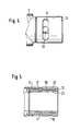
- FIG. 1 an embodiment according to the invention is shown in the open position.
- the active vacuum cleaner nozzle has a two-part housing, consisting of a lower housing part 1 and an upper housing part 2.
- a drive 3 in the form of a turbine wheel, shown only schematically, a gear 4 in the form of a pinion 4 and a brush roller 5.
- the upper housing part 2 can be pivoted relative to the lower housing part 1 about the axis of rotation 6 of the brush roller 5 between a closed position and the open position shown here.
- an intake manifold connection piece 8, 9, 10 is integrally formed on the housing, the intake pipe connection piece 8, 9, 10 through the dividing joint 7 between the upper housing part 2 and the lower housing part part 3 is separated into two areas.
- the intake manifold connection piece 8, 9, 10 has an overall cylindrical shape in cross section.
- a cylinder half-shell-like area 8 of the intake manifold connection piece 8, 9, 10 is part of the upper housing part 2; the remaining area of the intake manifold connection piece 8, 9, 10 is part of the lower housing part 1 and consists of an axially inner cylindrical half-shell-like region 9, which in the closed position is supplemented again with the cylindrical half-shell-like region 8 of the upper housing part 1 to form an overall cylindrically closed region, and an axially outer region cylindrical circular closed region 10.
- the cylindrical half-shell-like area 8 of the upper housing part 2 has a locking element in the form of a resilient latching tongue 11, which has a radially outwardly projecting latching button 12 on its free end on its radial outside.
- the resilient latching tongue 11 is formed in the simplest manner by two slot-like incisions extending in the axial direction in the intake pipe-side end of the cylinder half-shell-like region 8. The spring action of the locking tongue 11 takes place through the elastic restoring force of the material of the housing parts 1, 2, which preferably consist of plastic.
- a locking sleeve 13 is slipped onto the intake manifold connection piece 8, 9, 10. This locking sleeve 13 can be moved between the open position, as shown in FIG. 1, and the locking position, as can be seen, for example, from FIG. 2, in the axial direction on the intake manifold connection piece 8, 9, 10.
- the locking sleeve 13 has a recess in the form of an elongated circular slot-like sleeve slot 14 extending in the circumferential direction.
- the width of this sleeve slot 14 corresponds essentially to the diameter of the locking button 12.
- the locking button 12 and the sleeve slot 14 are brought into axial alignment, so that the locking button 12 snaps radially outward into the sleeve slot 14 due to the elastic restoring force of the resilient locking tongue 11.
- the locking sleeve 13 is secured against axial sliding down from the intake manifold connector 8,9,10, while a reliable locking effect with respect to the housing parts 1 and 2 is achieved.
- the locking sleeve 13 can be rotated by a limited angle in relation to the housing of the vacuum cleaner nozzle in the locking position shown in FIG. 2. This can be seen in particular from the illustration in FIG. 4.
- the lower housing part has a stop element in the form of a radially projecting pin 15 at the intake-pipe end of the intake-pipe connection piece 8, 9, 10.
- the pin 15 is in engagement with two T-shaped sleeve slots 16 and 17 of the locking sleeve 13.
- the arc length of the sleeve slot 17 is dimensioned at least as much as the arc length of the first sleeve slot 14 so as not to impede the rotatability of the locking sleeve 13.
- the axially extending sleeve slot 16 in cooperation with the pin 15 when unlocking and thus axially pushing back the locking sleeve 13, constitutes a stop which reliably prevents the locking sleeve from being inadvertently released from the intake manifold connection piece.
- the length of the sleeve slot 16 is to be chosen in each case that in the end position both the release of the resilient locking tongue 11 and the cylinder half-shell-like area 8 of the intake manifold connection piece of the housing top 2 takes place.
- the locking sleeve After unlocking the housing, the locking sleeve is on the intake manifold connection in the position shown in Fig. 1. In this position, rotation of the locking sleeve is not possible due to the axially extending sleeve slot 16.
- the locking sleeve 13 can be moved axially inwards into a position which corresponds approximately to the locking position; this position is brought about by the axial abutment of the pin 15 on the axially outer longitudinal wall 18 of the sleeve slot 17. In this position, the locking sleeve 13 can now be rotated by an angle corresponding to the arc length of the sleeve slot 17.
- the locking sleeve 13 has in its inner wall a radially closed groove 19 which extends essentially parallel to the sleeve slot 16, as indicated by the broken line in the illustration according to FIG. 3.
- the groove 19 is connected with its axially outer end to the sleeve slot 17 and opens with its axially opposite end at the nozzle-side end 20 of the locking sleeve 13.
- the height of the pin 15 and the radial depth of the groove 19 are so coordinated that the pin 15 is movable in the groove 19 without hindrance.
- the locking sleeve 13 By turning the locking sleeve 13 with the housing open, the locking sleeve 13 can now be brought into a position with respect to the pin 15 in which the locking sleeve 13 can be completely removed from the intake manifold connection piece 8, 9, 10. Since pulling requires a conscious rotation of the locking sleeve, accidental sliding down is practically impossible.
- the locking sleeve 13 is designed as a double-walled sleeve with an inner wall 21 and an outer wall 22.
- the slot-like sleeve slots 14, 16, 17 and the groove 19 are formed in the sleeve outer wall 22.
- the locking sleeve 13 is attached to the intake manifold connector 8,9,10, the wall of the intake manifold connector being encompassed inside by the inner wall 21 and outside by the outer wall 22 of the locking sleeve 13 with little radial play.
- the inside diameter d of the locking sleeve 13 corresponds essentially to the outside diameter of the suction tube, not shown, of a vacuum cleaner to which the vacuum cleaner nozzle is to be connected.
- the inner diameter d of the locking sleeve 13 can decrease conically inwards.
Landscapes
- Engineering & Computer Science (AREA)
- Mechanical Engineering (AREA)
- Nozzles For Electric Vacuum Cleaners (AREA)
- Electric Vacuum Cleaner (AREA)
- Jet Pumps And Other Pumps (AREA)
- Organic Low-Molecular-Weight Compounds And Preparation Thereof (AREA)
Applications Claiming Priority (2)
| Application Number | Priority Date | Filing Date | Title |
|---|---|---|---|
| DE9109809U | 1991-08-07 | ||
| DE9109809U DE9109809U1 (fr) | 1991-08-07 | 1991-08-07 |
Publications (2)
| Publication Number | Publication Date |
|---|---|
| EP0526694A1 true EP0526694A1 (fr) | 1993-02-10 |
| EP0526694B1 EP0526694B1 (fr) | 1998-02-04 |
Family
ID=6870092
Family Applications (1)
| Application Number | Title | Priority Date | Filing Date |
|---|---|---|---|
| EP92105922A Expired - Lifetime EP0526694B1 (fr) | 1991-08-07 | 1992-04-06 | Buse avec dispositif actif pour aspirateur |
Country Status (4)
| Country | Link |
|---|---|
| US (1) | US5351362A (fr) |
| EP (1) | EP0526694B1 (fr) |
| AT (1) | ATE162939T1 (fr) |
| DE (2) | DE9109809U1 (fr) |
Cited By (3)
| Publication number | Priority date | Publication date | Assignee | Title |
|---|---|---|---|---|
| US6513190B1 (en) | 2000-04-21 | 2003-02-04 | The Hoover Company | Turbine powered vacuum cleaner nozzle |
| EP1537815A2 (fr) * | 2003-12-05 | 2005-06-08 | Samsung Gwangju Electronics Co., Ltd. | Ensemble brosse pour un aspirateur |
| CN105595909A (zh) * | 2015-12-27 | 2016-05-25 | 天津达瑞福科技有限公司 | 一种智能控制的吸尘器 |
Families Citing this family (22)
| Publication number | Priority date | Publication date | Assignee | Title |
|---|---|---|---|---|
| DE19517700A1 (de) * | 1995-05-13 | 1996-11-14 | Vorwerk Co Interholding | Aufnahmevorrichtung für eine oder mit einer Bürste für ein Bodenreinigungsgerät |
| DE10238880A1 (de) * | 2002-08-24 | 2004-03-04 | Vorwerk & Co. Interholding Gmbh | Vorsatzgerät für einen Staubsauger |
| GB0228152D0 (en) * | 2002-12-03 | 2003-01-08 | Techtronic Ind Co Ltd | Cyclonic separators for suction cleaners |
| GB0228148D0 (en) * | 2002-12-03 | 2003-01-08 | Techtronic Ind Co Ltd | Dust separator and collector arrangement for suction cleaner |
| GB0228153D0 (en) * | 2002-12-03 | 2003-01-08 | Techtronic Ind Co Ltd | Suction cleaners |
| GB0228481D0 (en) * | 2002-12-06 | 2003-01-08 | Techtronic Ind Co Ltd | Head for a suction cleaner |
| MXPA05006097A (es) * | 2002-12-06 | 2006-05-25 | Techtronic Ind Co Ltd | Cabeza para una limpiadora de succion. |
| KR100531224B1 (ko) * | 2003-06-09 | 2005-11-28 | 삼성광주전자 주식회사 | 터빈브러시 |
| GB2416482B (en) * | 2004-07-22 | 2007-12-05 | Techtronic Ind Co Ltd | Hose assembly for suction cleaner |
| KR20060019739A (ko) * | 2004-08-30 | 2006-03-06 | 엘지전자 주식회사 | 진공 청소기의 흡입 노즐 구조 |
| GB2417674B (en) * | 2004-09-02 | 2007-12-19 | Techtronic Ind Co Ltd | Suction cleaners |
| GB2422090B (en) * | 2005-01-12 | 2008-07-02 | Techtronic Ind Co Ltd | Head for a suction cleaner |
| GB2423037A (en) * | 2005-02-15 | 2006-08-16 | Techtronic Ind Co Ltd | Cyclonic separator for suction cleaner |
| GB2425246B (en) * | 2005-04-21 | 2008-07-23 | Vax Ltd | Dust separator/collector assembly for suction cleaner |
| AU2006201894B2 (en) * | 2005-05-05 | 2010-09-16 | Bissell Inc. | Vacuum accessory tool |
| KR100730232B1 (ko) * | 2006-03-06 | 2007-06-19 | 삼성광주전자 주식회사 | 진공청소기의 흡입브러쉬 |
| WO2012105627A1 (fr) * | 2011-02-03 | 2012-08-09 | 株式会社湯山製作所 | Dispositif d'emballage de médicaments |
| WO2017117898A1 (fr) * | 2016-01-04 | 2017-07-13 | 江苏美的清洁电器股份有限公司 | Brosse à planchers pour aspirateur et aspirateur comprenant cette dernière |
| CA2971301A1 (fr) * | 2016-01-04 | 2017-07-04 | Jiangsu Midea Cleaning Appliances Co., Ltd. | Brosse de sol pour aspirateur et aspirateur dote de ladite brosse |
| CN205433565U (zh) * | 2016-01-04 | 2016-08-10 | 江苏美的清洁电器股份有限公司 | 地刷和吸尘器 |
| CN110786779B (zh) * | 2018-08-03 | 2022-04-19 | 添可智能科技有限公司 | 地刷控制系统及地刷 |
| CN110558712A (zh) * | 2019-10-21 | 2019-12-13 | 宁波恩邦工具有限公司 | 一种多功能刷 |
Citations (5)
| Publication number | Priority date | Publication date | Assignee | Title |
|---|---|---|---|---|
| DE1040849B (de) * | 1952-06-17 | 1958-10-09 | Electrolux Ab | Klemmvorrichtung zur Verbindung teleskopartig ineinander einsetzbarer und/oder verschiebbarer Teile, insbesondere von Staubsaugerrohren |
| DE1243346B (de) * | 1959-03-06 | 1967-06-29 | Preco Inc | Luftturbine fuer den Antrieb eines Reinigungswerkzeuges in einem Staubsaugermundstueck |
| EP0061826A1 (fr) * | 1981-03-26 | 1982-10-06 | Black & Decker Inc. | Buse d'aspirateur pour utilisation sur surfaces horizontales et verticales |
| DE3643498A1 (de) * | 1986-12-19 | 1988-06-30 | Vorwerk Co Interholding | Rastverbindung fuer staubsauger und deren zubehoer |
| DE3722961A1 (de) * | 1987-07-11 | 1989-01-19 | Licentia Gmbh | Teleskoprohr |
Family Cites Families (18)
| Publication number | Priority date | Publication date | Assignee | Title |
|---|---|---|---|---|
| US2016158A (en) * | 1935-03-13 | 1935-10-01 | Vartanian Martin | Spray device |
| US2706826A (en) * | 1949-10-04 | 1955-04-26 | Martin Parry Corp | Suction cleaner floor tool |
| US2672643A (en) * | 1950-03-27 | 1954-03-23 | Singer Mfg Co | Vacuum cleaner dust brush supporting means |
| US3005224A (en) * | 1958-10-23 | 1961-10-24 | Preco Inc | Air flow operated brush devices for vacuum cleaners |
| US2997729A (en) * | 1959-01-20 | 1961-08-29 | Royal Appliance Mfg Company | Suction cleaner nozzle construction |
| US2974347A (en) * | 1959-09-08 | 1961-03-14 | Scovill Manufacturing Co | Suction cleaner nozzle |
| US3071799A (en) * | 1960-07-11 | 1963-01-08 | Sunbeam Corp | Cleaning attachment |
| NL134452C (fr) * | 1966-02-18 | |||
| GB1301324A (fr) * | 1969-03-10 | 1972-12-29 | ||
| US3614705A (en) * | 1970-01-07 | 1971-10-19 | Cons Foods Corp | System and apparatus for electrically connecting a vacuum cleaner and a remote motor driven brush tool |
| US3872539A (en) * | 1973-02-12 | 1975-03-25 | John S Doyel | Hand-held cleaning device utilizing air flow and broom action |
| US3936905A (en) * | 1974-06-03 | 1976-02-10 | Whirlpool Corporation | Vacuum cleaner suction tool |
| US4306330A (en) * | 1979-09-04 | 1981-12-22 | Black & Decker Inc. | Air-powered vacuum cleaner floor tool |
| US4841594A (en) * | 1986-11-07 | 1989-06-27 | Black & Decker, Inc. | Cordless vacuum cleaner with power brush |
| US5101534A (en) * | 1989-04-17 | 1992-04-07 | Hitachi, Ltd. | Suction nozzle with rotary brush for vacuum cleaner |
| US4980945A (en) * | 1989-11-27 | 1991-01-01 | Whirlpool Corporation | Safety interlock device for a vacuum cleaner |
| US5031266A (en) * | 1989-12-21 | 1991-07-16 | Whirlpool Corporation | Vacuum cleaner wand seal |
| US5088149A (en) * | 1990-08-06 | 1992-02-18 | Tennant Company | Vacuum powered scrub head |
-
1991
- 1991-08-07 DE DE9109809U patent/DE9109809U1/de not_active Expired - Lifetime
-
1992
- 1992-04-06 AT AT92105922T patent/ATE162939T1/de not_active IP Right Cessation
- 1992-04-06 EP EP92105922A patent/EP0526694B1/fr not_active Expired - Lifetime
- 1992-04-06 DE DE59209178T patent/DE59209178D1/de not_active Expired - Fee Related
- 1992-07-22 US US07/918,413 patent/US5351362A/en not_active Expired - Fee Related
Patent Citations (5)
| Publication number | Priority date | Publication date | Assignee | Title |
|---|---|---|---|---|
| DE1040849B (de) * | 1952-06-17 | 1958-10-09 | Electrolux Ab | Klemmvorrichtung zur Verbindung teleskopartig ineinander einsetzbarer und/oder verschiebbarer Teile, insbesondere von Staubsaugerrohren |
| DE1243346B (de) * | 1959-03-06 | 1967-06-29 | Preco Inc | Luftturbine fuer den Antrieb eines Reinigungswerkzeuges in einem Staubsaugermundstueck |
| EP0061826A1 (fr) * | 1981-03-26 | 1982-10-06 | Black & Decker Inc. | Buse d'aspirateur pour utilisation sur surfaces horizontales et verticales |
| DE3643498A1 (de) * | 1986-12-19 | 1988-06-30 | Vorwerk Co Interholding | Rastverbindung fuer staubsauger und deren zubehoer |
| DE3722961A1 (de) * | 1987-07-11 | 1989-01-19 | Licentia Gmbh | Teleskoprohr |
Cited By (4)
| Publication number | Priority date | Publication date | Assignee | Title |
|---|---|---|---|---|
| US6513190B1 (en) | 2000-04-21 | 2003-02-04 | The Hoover Company | Turbine powered vacuum cleaner nozzle |
| EP1537815A2 (fr) * | 2003-12-05 | 2005-06-08 | Samsung Gwangju Electronics Co., Ltd. | Ensemble brosse pour un aspirateur |
| EP1537815A3 (fr) * | 2003-12-05 | 2006-06-21 | Samsung Gwangju Electronics Co., Ltd. | Ensemble brosse pour un aspirateur |
| CN105595909A (zh) * | 2015-12-27 | 2016-05-25 | 天津达瑞福科技有限公司 | 一种智能控制的吸尘器 |
Also Published As
| Publication number | Publication date |
|---|---|
| EP0526694B1 (fr) | 1998-02-04 |
| DE9109809U1 (fr) | 1991-10-31 |
| US5351362A (en) | 1994-10-04 |
| DE59209178D1 (de) | 1998-03-12 |
| ATE162939T1 (de) | 1998-02-15 |
Similar Documents
| Publication | Publication Date | Title |
|---|---|---|
| EP0526694B1 (fr) | Buse avec dispositif actif pour aspirateur | |
| DE69813944T2 (de) | Staubsauger mit schwenkbarem Schaftrohr | |
| DE10200070B4 (de) | Klappbehälter mit einem Behälterboden und vier klappbaren Seitenwänden | |
| EP0263456A1 (fr) | Appareil manuel de nettoyage de surfaces planes, notamment pour des vitres | |
| DE1775302B2 (de) | Schlauchkupplung | |
| EP0277628A2 (fr) | Dispositif de nettoyage par succion | |
| DE60124266T2 (de) | Staubsaugermundstück | |
| DE2621631B2 (de) | Schlauchkupplung fur Staubsauger | |
| DE3302297A1 (de) | Staubsauger | |
| EP0681444A1 (fr) | Appareil pour l'entretien de sols, notamment aspirateur, pourvu de poils de brosserie disposes de preference sur le bord exterieur et diriges vers le bas | |
| EP0975506B1 (fr) | Articulation pour le guidon d'un petit vehicule | |
| EP0803225B1 (fr) | Dispositif pour accoupler de façon amovible un embout d'aspirateur à l'ouie d'aspiration d'un aspirateur | |
| DE7837444U1 (de) | Staubsauger | |
| DE19623690A1 (de) | Transport- und Lagerbehälter | |
| WO2004097132A1 (fr) | Dispositif de fixation d'une paroi coulissante | |
| EP0556420B1 (fr) | Manuelle d'entraînement pour partie mobile d'un toit de véhicule | |
| EP0234215B1 (fr) | Index pour une scie de table et d'onglets | |
| EP0520175B1 (fr) | Buse avec dispositif auxiliaire pour aspirateur | |
| EP0677270A1 (fr) | Aspirateur avec sac à poussières | |
| DE10037082B4 (de) | Hochdruckreinigungsgerät für im wesentlichen ebene Flächen | |
| DE102005010983B3 (de) | Luftstromregler für Staubsauger | |
| DE2829439C2 (de) | Staubsauger mit einem Saugschlauch, an dem ein Anschlußstutzen vorgesehen ist | |
| DE102007011320B4 (de) | Fluidische Steckkupplungsvorrichtung | |
| EP0916031B1 (fr) | Articulation pour pieces pivotantes d'une poussette, d'une tondeuse a gazon ou d'un petit vehicule similaire | |
| DE3643478C2 (fr) |
Legal Events
| Date | Code | Title | Description |
|---|---|---|---|
| PUAI | Public reference made under article 153(3) epc to a published international application that has entered the european phase |
Free format text: ORIGINAL CODE: 0009012 |
|
| AK | Designated contracting states |
Kind code of ref document: A1 Designated state(s): AT DE ES FR GB IT NL SE |
|
| 17P | Request for examination filed |
Effective date: 19930806 |
|
| GRAG | Despatch of communication of intention to grant |
Free format text: ORIGINAL CODE: EPIDOS AGRA |
|
| GRAG | Despatch of communication of intention to grant |
Free format text: ORIGINAL CODE: EPIDOS AGRA |
|
| GRAH | Despatch of communication of intention to grant a patent |
Free format text: ORIGINAL CODE: EPIDOS IGRA |
|
| 17Q | First examination report despatched |
Effective date: 19970626 |
|
| GRAH | Despatch of communication of intention to grant a patent |
Free format text: ORIGINAL CODE: EPIDOS IGRA |
|
| GRAA | (expected) grant |
Free format text: ORIGINAL CODE: 0009210 |
|
| AK | Designated contracting states |
Kind code of ref document: B1 Designated state(s): AT DE ES FR GB IT NL SE |
|
| PG25 | Lapsed in a contracting state [announced via postgrant information from national office to epo] |
Ref country code: IT Free format text: LAPSE BECAUSE OF FAILURE TO SUBMIT A TRANSLATION OF THE DESCRIPTION OR TO PAY THE FEE WITHIN THE PRE;WARNING: LAPSES OF ITALIAN PATENTS WITH EFFECTIVE DATE BEFORE 2007 MAY HAVE OCCURRED AT ANY TIME BEFORE 2007. THE CORRECT EFFECTIVE DATE MAY BE DIFFERENT FROM THE ONE RECORDED.SCRIBED TIME-LIMIT Effective date: 19980204 Ref country code: GB Free format text: LAPSE BECAUSE OF FAILURE TO SUBMIT A TRANSLATION OF THE DESCRIPTION OR TO PAY THE FEE WITHIN THE PRESCRIBED TIME-LIMIT Effective date: 19980204 Ref country code: ES Free format text: THE PATENT HAS BEEN ANNULLED BY A DECISION OF A NATIONAL AUTHORITY Effective date: 19980204 Ref country code: NL Free format text: LAPSE BECAUSE OF FAILURE TO SUBMIT A TRANSLATION OF THE DESCRIPTION OR TO PAY THE FEE WITHIN THE PRESCRIBED TIME-LIMIT Effective date: 19980204 |
|
| REF | Corresponds to: |
Ref document number: 162939 Country of ref document: AT Date of ref document: 19980215 Kind code of ref document: T |
|
| REF | Corresponds to: |
Ref document number: 59209178 Country of ref document: DE Date of ref document: 19980312 |
|
| PG25 | Lapsed in a contracting state [announced via postgrant information from national office to epo] |
Ref country code: AT Free format text: LAPSE BECAUSE OF NON-PAYMENT OF DUE FEES Effective date: 19980406 |
|
| ET | Fr: translation filed | ||
| NLV1 | Nl: lapsed or annulled due to failure to fulfill the requirements of art. 29p and 29m of the patents act | ||
| GBV | Gb: ep patent (uk) treated as always having been void in accordance with gb section 77(7)/1977 [no translation filed] |
Effective date: 19980204 |
|
| PLBE | No opposition filed within time limit |
Free format text: ORIGINAL CODE: 0009261 |
|
| STAA | Information on the status of an ep patent application or granted ep patent |
Free format text: STATUS: NO OPPOSITION FILED WITHIN TIME LIMIT |
|
| 26N | No opposition filed | ||
| PGFP | Annual fee paid to national office [announced via postgrant information from national office to epo] |
Ref country code: DE Payment date: 20090610 Year of fee payment: 18 Ref country code: SE Payment date: 20090427 Year of fee payment: 18 Ref country code: FR Payment date: 20090420 Year of fee payment: 18 |
|
| EUG | Se: european patent has lapsed | ||
| REG | Reference to a national code |
Ref country code: FR Ref legal event code: ST Effective date: 20101230 |
|
| PG25 | Lapsed in a contracting state [announced via postgrant information from national office to epo] |
Ref country code: FR Free format text: LAPSE BECAUSE OF NON-PAYMENT OF DUE FEES Effective date: 20100430 |
|
| PG25 | Lapsed in a contracting state [announced via postgrant information from national office to epo] |
Ref country code: DE Free format text: LAPSE BECAUSE OF NON-PAYMENT OF DUE FEES Effective date: 20101103 |
|
| PG25 | Lapsed in a contracting state [announced via postgrant information from national office to epo] |
Ref country code: SE Free format text: LAPSE BECAUSE OF NON-PAYMENT OF DUE FEES Effective date: 20100407 |