EP0526694A1 - Active vacuum cleaner nozzle - Google Patents
Active vacuum cleaner nozzle Download PDFInfo
- Publication number
- EP0526694A1 EP0526694A1 EP92105922A EP92105922A EP0526694A1 EP 0526694 A1 EP0526694 A1 EP 0526694A1 EP 92105922 A EP92105922 A EP 92105922A EP 92105922 A EP92105922 A EP 92105922A EP 0526694 A1 EP0526694 A1 EP 0526694A1
- Authority
- EP
- European Patent Office
- Prior art keywords
- sleeve
- locking
- slot
- housing
- intake manifold
- Prior art date
- Legal status (The legal status is an assumption and is not a legal conclusion. Google has not performed a legal analysis and makes no representation as to the accuracy of the status listed.)
- Granted
Links
- 230000000295 complement effect Effects 0.000 claims description 3
- 230000005540 biological transmission Effects 0.000 claims description 2
- 238000000926 separation method Methods 0.000 abstract 1
- 230000000694 effects Effects 0.000 description 6
- 238000012423 maintenance Methods 0.000 description 5
- 238000004140 cleaning Methods 0.000 description 3
- 238000006073 displacement reaction Methods 0.000 description 3
- 239000002245 particle Substances 0.000 description 2
- 238000010521 absorption reaction Methods 0.000 description 1
- 230000004323 axial length Effects 0.000 description 1
- 230000000903 blocking effect Effects 0.000 description 1
- 230000001419 dependent effect Effects 0.000 description 1
- 239000000428 dust Substances 0.000 description 1
- 239000000835 fiber Substances 0.000 description 1
- 239000000463 material Substances 0.000 description 1
- 230000003068 static effect Effects 0.000 description 1
Images


Classifications
-
- A—HUMAN NECESSITIES
- A47—FURNITURE; DOMESTIC ARTICLES OR APPLIANCES; COFFEE MILLS; SPICE MILLS; SUCTION CLEANERS IN GENERAL
- A47L—DOMESTIC WASHING OR CLEANING; SUCTION CLEANERS IN GENERAL
- A47L9/00—Details or accessories of suction cleaners, e.g. mechanical means for controlling the suction or for effecting pulsating action; Storing devices specially adapted to suction cleaners or parts thereof; Carrying-vehicles specially adapted for suction cleaners
- A47L9/02—Nozzles
- A47L9/04—Nozzles with driven brushes or agitators
Definitions
- the invention relates to an active vacuum cleaner nozzle mentioned in the preamble of claim 1.
- the present invention relates specifically to a vacuum cleaner nozzle with an additional, driven brush roller.
- a generic active vacuum cleaner nozzle is known from the unpublished German patent application DE 41 21 130.8, which essentially consists of a two-part housing with an upper housing part and lower housing part, the upper housing part being pivoted about the axis of rotation of the brush roller from a closed position into an open position for maintenance of the housing interior can.
- the housing is locked in the closed position by a housing part of the drive housing which is provided with the intake manifold connecting piece and which is pivotable about the turbine axis of rotation running parallel to the brush axis.
- the opening of the lock and thus the nozzle housing takes place by pivoting the suction pipe and thus via the suction pipe connection piece of the turbine housing part into a maintenance position, while the locking takes place in that the suction pipe is brought into the working or operating position.
- This vacuum cleaner nozzle is quite satisfactory in terms of easy maintenance of the interior of the housing; however, unintentional unlocking and thus opening of the nozzle housing cannot be reliably avoided under all conditions, in particular not when carrying the entire vacuum cleaner with suction pipe and nozzle, the nozzle being lifted off the floor.
- the active vacuum cleaner nozzle has a two-part housing in which at least one brush roller, a drive and a transmission, which transmits the torque of the drive to the brush roller, are arranged.
- the drive can take place both electromotively and pneumatically, for example by a turbine wheel known per se, which is driven by the suction air of the vacuum cleaner.
- Gearbox in the sense of the present invention generally, but by no means exclusively, means a toothed belt drive.
- the upper housing part is pivotally mounted relative to the lower housing part between a first position allowing access to the housing interior and a lockable second position closing the housing, the pivot axis running at least parallel to the axis of rotation of the brush roller, but preferably coinciding therewith. In the last embodiment in particular, optimal access to the housing interior with all of its functional elements is made possible.
- the division joint between the two housing parts extends at least into the area of the intake manifold connection piece.
- “At least” means that in extreme cases the intake manifold connection piece can also be completely axially divided by the dividing joint.
- part of the intake manifold connection piece remains on the upper part of the housing and the second part of the intake pipe connection piece remains on the lower part of the housing.
- There is an axial locking sleeve on the intake manifold connection i.e. in the longitudinal direction of the intake manifold connection, arranged displaceably, wherein the displaceability must be ensured at least between a first position which enables the opening of the housing and a locking position.
- the locking position is characterized in that the locking sleeve in this position both areas of the intake manifold connection, i.e. encompasses both the area on the upper housing part and the area on the lower housing part and thus prevents the housing from being opened.
- At least one of the two housing parts in the area of the intake manifold connection piece has a first locking element, which in the closed position can be brought into releasable engagement with a complementary second locking element of the locking sleeve.
- Locking elements of this type can be arranged on the upper part or lower part of the housing or else on both housing parts.
- the intake manifold connection piece is essentially cylindrical overall.
- the dividing joint can extend over the entire axial length of the intake manifold connection piece.
- the dividing joint preferably runs such that only the axially inner region, that is to say pointing away from the end of the intake manifold connecting piece on the intake manifold side, is divided by the dividing joint in such a way that an essentially cylindrical half-shell-like region of the intake manifold connecting piece is formed which connects to the first of the two housing parts, for example to the
- the upper housing part is integrally formed, while the remaining part of the intake manifold connection piece is part of the second housing part, in this case, for example, the lower housing part.
- the intake manifold connection area on the lower housing part consists of a cylindrical, circularly closed region on the intake manifold side, which is molded onto the lower housing part via a cylindrical half-shell-like region which is open towards the upper housing part.
- the two cylindrical half-shell regions on the upper housing part and lower housing part add up again to form a cylindrically closed region of the intake manifold connection piece.
- the first locking element is preferably designed as a resilient latching tongue on the cylinder half-shell-like region of the first housing part, which, or the blocking region thereof, can be brought into releasable engagement in a recess in the locking sleeve.
- the recess of the locking sleeve thus represents the second locking element complementary to the first locking element.
- the latching tongue can be formed in the simplest manner by two slit-like incisions in the end of the cylinder half-shell-like area on the intake manifold side; the actual locking element is formed by a locking button, which is arranged on the free end of the locking tongue projecting radially outward.
- the recess of the locking sleeve which receives the latching button of the latching spring tongue can be designed in any way as long as the locking effect is reliably ensured.
- this recess is designed as a circular arc-shaped, elongated, slot-like sleeve slot, which on the one hand reliably locks the locking action in the axial direction and thus the locking action against pulling down the locking sleeve, and on the other hand enables a limited rotation of the locking sleeve on the intake manifold connection piece. The rotatability takes place through an angle limited depending on the length of the sleeve slot.
- Such rotatability of the locking sleeve in relation to the suction pipe connection piece and thus in relation to the vacuum cleaner nozzle is particularly advantageous if the locking sleeve serves in addition to its locking effect to simultaneously connect the nozzle to the suction pipe of a vacuum cleaner, since then the locking sleeve acts as a known swivel joint which Manageability of the vacuum cleaner improved.
- the second housing part that is to say the housing part which has no locking element, has a stop element which is arranged essentially at the end of the intake manifold connection piece on the intake pipe side and engages in a second slot-like sleeve slot in the locking sleeve which runs essentially in the direction of the intake pipe connection piece.
- the stop element and the second slot-like sleeve slot are preferably, but by no means exclusively, essentially diametrically opposite the locking element, for example the detent spring.
- This pairing of the stop element - second sleeve slot enables the locking sleeve to be guided axially on the intake manifold connection piece, the length of this sleeve slot limiting the axial displacement of the locking sleeve after release by the resilient latching tongue.
- the stop element together with the second sleeve slot, acts as a safeguard against inadvertent sliding down of the locking sleeve from the intake manifold connection piece.
- the locking sleeve In order to enable the locking sleeve to be rotated on the intake manifold connection piece in the closed position and thus in the working position despite the axial guidance and securing, the locking sleeve preferably has a third slot-like, circular arc-shaped sleeve slot in the circumferential direction in the locking sleeve, which is connected to the second sleeve slot in a T-shape , wherein its length corresponds at least to the length of the first sleeve slot, which cooperates with the resilient locking tongue.
- the stop element on the second housing part acts as a safeguard against inadvertent falling or pulling off the locking sleeve from the intake manifold connection piece.
- the locking sleeve has in its inner wall a radially outwardly closed groove running essentially parallel to the second sleeve slot.
- This groove runs from the third sleeve slot to the nozzle-side end of the sleeve and opens there. In other words, this groove creates a continuous connection between the third sleeve slot and the environment.
- the stop element has a radial height which is at least slightly less than the radial depth of the groove. The width of the groove is of course to be chosen so that the stop element can slide at least with little lateral play in the groove.
- the locking sleeve is removed from the intake manifold connection in the following way: First the locking latch button is actuated and thus releases the recess of the locking sleeve. This enables the locking sleeve to be moved in the axial direction, the locking sleeve sliding with the second axially extending sleeve slot along the stop element. The axial displacement takes place up to the stop of the stop element at the end of the second sleeve slot, the suction tube region of the housing part having the locking element being released in this position and the opening of the housing being made possible.
- the locking sleeve After opening, the locking sleeve is again axially displaced towards the nozzle body until the stop element comes into engagement with the third sleeve slot running in the circumferential direction. In this position, the locking sleeve on the intake manifold connection piece is rotated into a position in which the stop element can slide into the groove in the inner wall of the sleeve, which enables the sleeve to be pulled off the intake pipe connection piece.
- the locking sleeve itself can be designed in the simplest way as a single-walled sleeve which surrounds the intake manifold connecting piece on the outside.
- the inner diameter of the suction pipe connection piece must correspond to the outer diameter of the suction pipe onto which the vacuum cleaner nozzle is to be attached.
- the locking sleeve is designed as a double-walled sleeve, the inside diameter of which corresponds essentially to the outside diameter of the suction pipe to be connected, the wall of the suction pipe connection piece being encompassed by the inner wall and the outside by the outer wall of the locking sleeve with little radial play, and the sleeve slots and / or the groove are provided in the sleeve outer wall.
- the vacuum cleaner nozzle can also be easily adapted to different suction pipe diameters in that, with the nozzle unchanged, only the removable locking sleeve is replaced or replaced by a sleeve with a corresponding inner diameter needs to be.
- FIG. 1 an embodiment according to the invention is shown in the open position.
- the active vacuum cleaner nozzle has a two-part housing, consisting of a lower housing part 1 and an upper housing part 2.
- a drive 3 in the form of a turbine wheel, shown only schematically, a gear 4 in the form of a pinion 4 and a brush roller 5.
- the upper housing part 2 can be pivoted relative to the lower housing part 1 about the axis of rotation 6 of the brush roller 5 between a closed position and the open position shown here.
- an intake manifold connection piece 8, 9, 10 is integrally formed on the housing, the intake pipe connection piece 8, 9, 10 through the dividing joint 7 between the upper housing part 2 and the lower housing part part 3 is separated into two areas.
- the intake manifold connection piece 8, 9, 10 has an overall cylindrical shape in cross section.
- a cylinder half-shell-like area 8 of the intake manifold connection piece 8, 9, 10 is part of the upper housing part 2; the remaining area of the intake manifold connection piece 8, 9, 10 is part of the lower housing part 1 and consists of an axially inner cylindrical half-shell-like region 9, which in the closed position is supplemented again with the cylindrical half-shell-like region 8 of the upper housing part 1 to form an overall cylindrically closed region, and an axially outer region cylindrical circular closed region 10.
- the cylindrical half-shell-like area 8 of the upper housing part 2 has a locking element in the form of a resilient latching tongue 11, which has a radially outwardly projecting latching button 12 on its free end on its radial outside.
- the resilient latching tongue 11 is formed in the simplest manner by two slot-like incisions extending in the axial direction in the intake pipe-side end of the cylinder half-shell-like region 8. The spring action of the locking tongue 11 takes place through the elastic restoring force of the material of the housing parts 1, 2, which preferably consist of plastic.
- a locking sleeve 13 is slipped onto the intake manifold connection piece 8, 9, 10. This locking sleeve 13 can be moved between the open position, as shown in FIG. 1, and the locking position, as can be seen, for example, from FIG. 2, in the axial direction on the intake manifold connection piece 8, 9, 10.
- the locking sleeve 13 has a recess in the form of an elongated circular slot-like sleeve slot 14 extending in the circumferential direction.
- the width of this sleeve slot 14 corresponds essentially to the diameter of the locking button 12.
- the locking button 12 and the sleeve slot 14 are brought into axial alignment, so that the locking button 12 snaps radially outward into the sleeve slot 14 due to the elastic restoring force of the resilient locking tongue 11.
- the locking sleeve 13 is secured against axial sliding down from the intake manifold connector 8,9,10, while a reliable locking effect with respect to the housing parts 1 and 2 is achieved.
- the locking sleeve 13 can be rotated by a limited angle in relation to the housing of the vacuum cleaner nozzle in the locking position shown in FIG. 2. This can be seen in particular from the illustration in FIG. 4.
- the lower housing part has a stop element in the form of a radially projecting pin 15 at the intake-pipe end of the intake-pipe connection piece 8, 9, 10.
- the pin 15 is in engagement with two T-shaped sleeve slots 16 and 17 of the locking sleeve 13.
- the arc length of the sleeve slot 17 is dimensioned at least as much as the arc length of the first sleeve slot 14 so as not to impede the rotatability of the locking sleeve 13.
- the axially extending sleeve slot 16 in cooperation with the pin 15 when unlocking and thus axially pushing back the locking sleeve 13, constitutes a stop which reliably prevents the locking sleeve from being inadvertently released from the intake manifold connection piece.
- the length of the sleeve slot 16 is to be chosen in each case that in the end position both the release of the resilient locking tongue 11 and the cylinder half-shell-like area 8 of the intake manifold connection piece of the housing top 2 takes place.
- the locking sleeve After unlocking the housing, the locking sleeve is on the intake manifold connection in the position shown in Fig. 1. In this position, rotation of the locking sleeve is not possible due to the axially extending sleeve slot 16.
- the locking sleeve 13 can be moved axially inwards into a position which corresponds approximately to the locking position; this position is brought about by the axial abutment of the pin 15 on the axially outer longitudinal wall 18 of the sleeve slot 17. In this position, the locking sleeve 13 can now be rotated by an angle corresponding to the arc length of the sleeve slot 17.
- the locking sleeve 13 has in its inner wall a radially closed groove 19 which extends essentially parallel to the sleeve slot 16, as indicated by the broken line in the illustration according to FIG. 3.
- the groove 19 is connected with its axially outer end to the sleeve slot 17 and opens with its axially opposite end at the nozzle-side end 20 of the locking sleeve 13.
- the height of the pin 15 and the radial depth of the groove 19 are so coordinated that the pin 15 is movable in the groove 19 without hindrance.
- the locking sleeve 13 By turning the locking sleeve 13 with the housing open, the locking sleeve 13 can now be brought into a position with respect to the pin 15 in which the locking sleeve 13 can be completely removed from the intake manifold connection piece 8, 9, 10. Since pulling requires a conscious rotation of the locking sleeve, accidental sliding down is practically impossible.
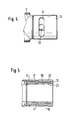
- the locking sleeve 13 is designed as a double-walled sleeve with an inner wall 21 and an outer wall 22.
- the slot-like sleeve slots 14, 16, 17 and the groove 19 are formed in the sleeve outer wall 22.
- the locking sleeve 13 is attached to the intake manifold connector 8,9,10, the wall of the intake manifold connector being encompassed inside by the inner wall 21 and outside by the outer wall 22 of the locking sleeve 13 with little radial play.
- the inside diameter d of the locking sleeve 13 corresponds essentially to the outside diameter of the suction tube, not shown, of a vacuum cleaner to which the vacuum cleaner nozzle is to be connected.
- the inner diameter d of the locking sleeve 13 can decrease conically inwards.
Abstract
Description
Die Erfindung betrifft eine aktive Staubsaugerdüse der im Oberbegriff des Patentanspruchs 1 genannten Art.The invention relates to an active vacuum cleaner nozzle mentioned in the preamble of claim 1.
Gegenüber sogenannten statischen Staubsaugerdüsen, d.h. Düsen, die ohne Hilfselemente lediglich saugend reinigen, haben sich sog. aktive Staubsaugerdüsen, d.h. Düsen durchgesetzt, die innerhalb der Düse selbst zusätzlich zur Saugwirkung eine aktiv reinigende Wirkung erzeugen. Verbreitet sind zu diesem Zweck elektromotorisch oder pneumatisch angetriebene Bürstenwalzen im Einsatz.Compared to so-called static vacuum cleaner nozzles, i.e. Nozzles that only vacuum clean without auxiliary elements have so-called active vacuum cleaner nozzles, i.e. Nozzles enforced, which generate an active cleaning effect in addition to the suction effect within the nozzle. Electromotive or pneumatically driven brush rollers are widely used for this purpose.
In diesem Sinne betrifft die vorliegende Erfindung speziell eine Staubsaugerdüse mit zusätzlicher, angetriebener Bürstenwalze.In this sense, the present invention relates specifically to a vacuum cleaner nozzle with an additional, driven brush roller.
Bei aktiven Staubsaugerdüsen dieser Art muß für den Komfort einer verbesserten Reinigungswirkung die Unbequemlichkeit einer Wartung der Düse hingenommen werden. Durch die verbesserte Aufnahmefähigkeit der Düse gelangen nicht nur feinste Staubpartikel, sondern auch gröbere Partikel, Fäden und verfilzte Fasern in die Düse, die insbesondere im Bürstenbereich und, insbesondere bei Turbinenantrieben, auch im Turbinenbereich zu einer Beeinträchtigung der freien Drehbarkeit der Walze bzw. der Turbinenräder führen können.With active vacuum cleaner nozzles of this type, the inconvenience of maintenance of the nozzle must be accepted for the convenience of an improved cleaning effect. Due to the improved absorption capacity of the nozzle, not only the finest dust particles, but also coarser particles, threads and matted fibers get into the nozzle, which in particular in the brush area and, in particular in the case of turbine drives, also in the turbine area impair the free rotation of the roller or the turbine wheels being able to lead.
Aus der nicht vorveröffentlichten deutschen Patentanmeldung DE 41 21 130.8 ist eine gattungsgemäße aktive Staubsaugerdüse bekannt, die im wesentlichen aus einem zweiteiligen Gehäuse mit Gehäuseoberteil und Gehäuseunterteil besteht, wobei zwecks Wartung des Gehäuseinnenraumes das Gehäuseoberteil um die Drehachse der Bürstenwalze aus einer Schließstellung in eine Offenstellung geschwenkt werden kann. Die Verriegelung des Gehäuses in Schließstellung erfolgt dabei durch ein mit dem Saugrohranschlußstutzen versehenes Gehäuseteil des Antriebsgehäuses, das um die zur Bürstenachse parallel verlaufende Turbinendrehachse schwenkbar ist. Dabei erfolgt die Öffnung der Verriegelung und damit des Düsengehäuses durch Verschwenken des Saugrohrs und damit über den Saugrohranschlußstutzen des Turbinengehäuseteils in eine Wartungsstellung, während die Verriegelung dadurch erfolgt, daß das Saugrohr in die Arbeits- oder Betriebsstellung gebracht wird.A generic active vacuum cleaner nozzle is known from the unpublished German patent application DE 41 21 130.8, which essentially consists of a two-part housing with an upper housing part and lower housing part, the upper housing part being pivoted about the axis of rotation of the brush roller from a closed position into an open position for maintenance of the housing interior can. The housing is locked in the closed position by a housing part of the drive housing which is provided with the intake manifold connecting piece and which is pivotable about the turbine axis of rotation running parallel to the brush axis. The opening of the lock and thus the nozzle housing takes place by pivoting the suction pipe and thus via the suction pipe connection piece of the turbine housing part into a maintenance position, while the locking takes place in that the suction pipe is brought into the working or operating position.
Diese Staubsaugerdüse ist zwar hinsichtlich der leichten Wartung des Gehäuseinnenraums durchaus befriedigend; jedoch ist ein ungewolltes Entriegeln und damit Öffnen des Düsengehäuses nicht unter allen Bedingungen, insbesondere nicht beim Tragen des gesamten Staubsaugers mit Saugrohr und Düse, wobei die Düse vom Boden abgehoben wird, zuverlässig zu vermeiden.This vacuum cleaner nozzle is quite satisfactory in terms of easy maintenance of the interior of the housing; however, unintentional unlocking and thus opening of the nozzle housing cannot be reliably avoided under all conditions, in particular not when carrying the entire vacuum cleaner with suction pipe and nozzle, the nozzle being lifted off the floor.
Ausgehend von diesem Stand der Technik ist es die Aufgabe der vorliegenden Erfindung, eine aktive Staubsaugerdüse der eingangs genannten Art zu schaffen, die neben einer bequemen, benutzerfreundlichen Wartung und Zugänglichkeit des gesamten Düseninnenraums gleichzeitig eine absolut sichere Verriegelung des Gehäuses und damit einen zuverlässigen Schutz gegen ungewolltes Öffnen bietet.Based on this prior art, it is the object of the present invention to provide an active vacuum cleaner nozzle of the type mentioned which, in addition to convenient, user-friendly maintenance and accessibility of the entire interior of the nozzle, also provides an absolutely secure locking of the housing and thus reliable protection against unwanted Open offers.
Diese Aufgabe wird durch eine aktive Staubsaugerdüse gemäß der Lehre des Patentanspruchs 1 gelöst.This object is achieved by an active vacuum cleaner nozzle according to the teaching of claim 1.
Vorteilhafte Ausgestaltungen der Erfindung sind Gegenstand der Unteransprüche.Advantageous embodiments of the invention are the subject of the dependent claims.
Die aktive Staubsaugerdüse gemäß der vorliegenden Erfindung weist ein zweiteiliges Gehäuse auf, in dem mindestens eine Bürstenwalze, ein Antrieb und ein Getriebe, das das Drehmoment des Antriebs auf die Bürstenwalze überträgt, angeordnet sind. Der Antrieb kann dabei sowohl elektromotorisch als auch pneumatisch, beispielsweise durch ein an sich bekanntes Turbinenrad, das durch die Saugluft des Staubsaugers angetrieben wird, erfolgen. Getriebe im Sinn der vorliegenden Erfindung bedeutet dabei im Regelfalle, jedoch keineswegs ausschließlich, einen Zahnriementrieb. Das Gehäuseoberteil ist gegenüber dem Gehäuseunterteil zwischen einer den Zugang zum Gehäuseinnenraum erlaubenden ersten Stellung und einer verriegelbaren, das Gehäuse verschließenden zweiten Stellung verschwenkbar gelagert, wobei die Schwenkachse zumindest parallel zur Drehachse der Bürstenwalze verläuft, jedoch vorzugsweise mit dieser zusammenfällt. Insbesondere bei der letzten Ausführungsform wird ein optimaler Zugang zum Gehäuseinnenraum mit allen seinen Funktionselementen ermöglicht.The active vacuum cleaner nozzle according to the present invention has a two-part housing in which at least one brush roller, a drive and a transmission, which transmits the torque of the drive to the brush roller, are arranged. The drive can take place both electromotively and pneumatically, for example by a turbine wheel known per se, which is driven by the suction air of the vacuum cleaner. Gearbox in the sense of the present invention generally, but by no means exclusively, means a toothed belt drive. The upper housing part is pivotally mounted relative to the lower housing part between a first position allowing access to the housing interior and a lockable second position closing the housing, the pivot axis running at least parallel to the axis of rotation of the brush roller, but preferably coinciding therewith. In the last embodiment in particular, optimal access to the housing interior with all of its functional elements is made possible.
Die Teilungsfuge zwischen beiden Gehäuseteilen erstreckt sich gemäß der vorliegenden Erfindung zumindest bis in den Bereich des Saugrohranschlußstutzens. "Zumindest" bedeutet dabei, daß im Extremfall der Saugrohranschlußstutzen durch die Teilungsfuge auch vollständig axial geteilt sein kann. Mit anderen Worten, beim Aufklappen des Düsengehäuses verbleibt ein Teil des Saugrohranschlußstutzens am Gehäuseoberteil und der zweite Teil des Saugrohranschlußstutzens am Gehäuseunterteil. Auf dem Saugrohranschlußstutzen ist eine Verriegelungshülse axial, d.h. in Längsrichtung des Saugrohranschlußstutzens, verschiebbar angeordnet, wobei die Verschiebbarkeit zumindest zwischen einer ersten, die Öffnung des Gehäuses ermöglichenden Stellung und einer Verriegelungsstellung sichergestellt sein muß. Dabei ist die Verriegelungsstellung dadurch gekennzeichnet, daß die Verriegelungshülse in dieser Stellung beide Bereiche des Saugrohranschlußstutzens, d.h. sowohl den Bereich am Gehäuseoberteil als auch den Bereich am Gehäuseunterteil umgreift und somit ein Aufklappen des Gehäuses verhindert.According to the present invention, the division joint between the two housing parts extends at least into the area of the intake manifold connection piece. "At least" means that in extreme cases the intake manifold connection piece can also be completely axially divided by the dividing joint. In other words, when the nozzle housing is opened, part of the intake manifold connection piece remains on the upper part of the housing and the second part of the intake pipe connection piece remains on the lower part of the housing. There is an axial locking sleeve on the intake manifold connection, i.e. in the longitudinal direction of the intake manifold connection, arranged displaceably, wherein the displaceability must be ensured at least between a first position which enables the opening of the housing and a locking position. The locking position is characterized in that the locking sleeve in this position both areas of the intake manifold connection, i.e. encompasses both the area on the upper housing part and the area on the lower housing part and thus prevents the housing from being opened.
Zur Sicherung gegen ein unbeabsichtigtes axiales Verschieben der Verriegelungshülse aus der Verriegelungsstellung in die Offenstellung und damit zur Sicherung gegen ein ungewolltes Öffnen des Gehäuses weist zumindest eines der beiden Gehäuseteile im Bereich des Saugrohranschlußstutzens ein erstes Verriegelungselement auf, das in der Schließstellung mit einem dazu komplementären zweiten Verriegelungselement der Verriegelungshülse in lösbaren Eingriff bringbar ist. Derartige Verriegelungselemente können dabei am Oberteil oder Unterteil des Gehäuses oder aber auch an beiden Gehäuseteilen angeordnet sein.To secure against unintentional axial displacement of the locking sleeve the locking position in the open position and thus to secure against inadvertent opening of the housing, at least one of the two housing parts in the area of the intake manifold connection piece has a first locking element, which in the closed position can be brought into releasable engagement with a complementary second locking element of the locking sleeve. Locking elements of this type can be arranged on the upper part or lower part of the housing or else on both housing parts.
Gemäß einem bevorzugten Ausführungsbeispiel ist der Saugrohranschlußstutzen insgesamt im wesentlichen zylindrisch ausgebildet. Dabei kann, wie vorstehend erläutert, die Teilungsfuge über die gesamte axiale Länge des Saugrohranschlußstutzens verlaufen. Vorzugsweise jedoch verläuft die Teilungsfuge so, daß lediglich der axial innere, das heißt vom saugrohrseitigen Ende des Saugrohranschlußstutzens wegweisende Bereich durch die Teilungsfuge derart geteilt wird, daß ein im wesentlichen zylinderhalbschalenartiger Bereich des Saugrohranschlußstutzens entsteht, der an das erste der beiden Gehäuseteile, beispielsweise an das Gehäuseoberteil angeformt ist, während der übrige Teil des Saugrohranschlußstutzens Teil des zweiten Gehäuseteils, hier also beispielsweise des Gehäuseunterteils ist. Bei diesem Ausführungsbeispiel besteht der Saugrohranschlußstutzenbereich am Gehäuseunterteil aus einem saugrohrseitigen zylindrischen, kreisförmig geschlossenen Bereich, der über einen zylinderhalbschalenartigen Bereich, der zum Gehäuseoberteil hin offen ist, an das Gehäuseunterteil angeformt ist. Beim Schließen des Gehäuses ergänzen sich die beiden zylinderhalbschalenartigen Bereiche am Gehäuseoberteil und Gehäuseunterteil insgesamt wieder zu einem zylindrisch geschlossenen Bereich des Saugrohranschlußstutzens.According to a preferred embodiment, the intake manifold connection piece is essentially cylindrical overall. As explained above, the dividing joint can extend over the entire axial length of the intake manifold connection piece. However, the dividing joint preferably runs such that only the axially inner region, that is to say pointing away from the end of the intake manifold connecting piece on the intake manifold side, is divided by the dividing joint in such a way that an essentially cylindrical half-shell-like region of the intake manifold connecting piece is formed which connects to the first of the two housing parts, for example to the The upper housing part is integrally formed, while the remaining part of the intake manifold connection piece is part of the second housing part, in this case, for example, the lower housing part. In this exemplary embodiment, the intake manifold connection area on the lower housing part consists of a cylindrical, circularly closed region on the intake manifold side, which is molded onto the lower housing part via a cylindrical half-shell-like region which is open towards the upper housing part. When the housing is closed, the two cylindrical half-shell regions on the upper housing part and lower housing part add up again to form a cylindrically closed region of the intake manifold connection piece.
Bei vorstehendem Ausführungsbeispiel ist das erste Verriegelungselement vorzugsweise als federnde Rastzunge am zylinderhalbschalenartigen Bereich des ersten Gehäuseteils ausgebildet, die, bzw. deren Sperrbereich, in eine Ausnehmung der Verriegelungshülse in lösbaren Eingriff bringbar ist. Die Ausnehmung der Verriegelungshülse stellt damit das zweite, zum ersten Verriegelungselement komplementäre Verriegelungselement dar.In the above exemplary embodiment, the first locking element is preferably designed as a resilient latching tongue on the cylinder half-shell-like region of the first housing part, which, or the blocking region thereof, can be brought into releasable engagement in a recess in the locking sleeve. The recess of the locking sleeve thus represents the second locking element complementary to the first locking element.
Die Rastzunge kann in einfachster Weise durch zwei schlitzartige Einschnitte im saugrohrseitigen Ende des zylinderhalbschalenartigen Bereichs gebildet werden; das eigentliche Sperrelement wird durch einen Rastknopf gebildet, der auf dem freien Ende der Rastzunge nach radial außen vorspringend angeordnet ist.The latching tongue can be formed in the simplest manner by two slit-like incisions in the end of the cylinder half-shell-like area on the intake manifold side; the actual locking element is formed by a locking button, which is arranged on the free end of the locking tongue projecting radially outward.
Die den Rastknopf der Rastfederzunge aufnehmende Ausnehmung der Verriegelungshülse kann in an sich beliebiger Weise ausgestaltet sein, solange die Sperrwirkung zuverlässig gesichert ist. Vorzugsweise jedoch ist diese Ausnehmung als sich in Umfangsrichtung erstreckender kreisbogenförmiger langlochartiger Hülsenschlitz ausgebildet, wodurch einerseits die Sperrwirkung in axialer Richtung und damit die Sperrwirkung gegen ein Herabziehen der Verriegelungshülse zuverlässig gesichert ist und andererseits eine begrenzte Verdrehung der Verriegelungshülse auf dem Saugrohranschlußstutzen ermöglicht wird. Die Verdrehbarkeit erfolgt dabei um einen in Abhängigkeit von der Länge des Hülsenschlitzes begrenzten Winkel. Eine derartige Verdrehbarkeit der Verriegelungshülse gegenüber dem Saugrohranschlußstutzen und damit gegenüber der Staubsaugerdüse ist insbesondere dann von Vorteil, wenn die Verriegelungshülse neben ihrer Verschlußwirkung gleichzeitig zum Anschluß der Düse an das Saugrohr eines Staubsaugers dient, da dann die Verriegelungshülse als an sich bekanntes Drehgelenk wirkt, das die Handhabbarkeit des Staubsaugers verbessert.The recess of the locking sleeve which receives the latching button of the latching spring tongue can be designed in any way as long as the locking effect is reliably ensured. Preferably, however, this recess is designed as a circular arc-shaped, elongated, slot-like sleeve slot, which on the one hand reliably locks the locking action in the axial direction and thus the locking action against pulling down the locking sleeve, and on the other hand enables a limited rotation of the locking sleeve on the intake manifold connection piece. The rotatability takes place through an angle limited depending on the length of the sleeve slot. Such rotatability of the locking sleeve in relation to the suction pipe connection piece and thus in relation to the vacuum cleaner nozzle is particularly advantageous if the locking sleeve serves in addition to its locking effect to simultaneously connect the nozzle to the suction pipe of a vacuum cleaner, since then the locking sleeve acts as a known swivel joint which Manageability of the vacuum cleaner improved.
Gemäß einem weiteren Ausführungsbeispiel der Erfindung weist das zweite Gehäuseteil, also das Gehäuseteil, das kein Verriegelungselement aufweist, ein im wesentlichen am saugrohrseitigen Ende des Saugrohranschlußstutzens angeordnetes Anschlagelement auf, das in einen im wesentlichen in Richtung des Saugrohranschlußstutzens verlaufenden zweiten langlochartigen Hülsenschlitz der Verriegelungshülse eingreift. Anschlagelement und zweiter langlochartiger Hülsenschlitz liegen dabei vorzugsweise, jedoch keineswegs ausschließlich, dem Verriegelungselement, beispielsweise der Rastfeder, im wesentlich diametral gegenüber. Durch diese Paarung Anschlagelement - zweiter Hülsenschlitz wird eine axiale Führung der Verriegelungshülse auf dem Saugrohranschlußstutzen ermöglicht, wobei die Länge dieses Hülsenschlitzes die Axialverschiebbarkeit der Verriegelungshülse nach Freigabe durch die federnde Rastzunge begrenzt. Mit anderen Worten, das Anschlagelement wirkt zusammen mit dem zweiten Hülsenschlitz als Sicherung gegen ein unbeabsichtigtes Heruntergleiten der Verriegelungshülse vom Saugrohranschlußstutzen.According to a further exemplary embodiment of the invention, the second housing part, that is to say the housing part which has no locking element, has a stop element which is arranged essentially at the end of the intake manifold connection piece on the intake pipe side and engages in a second slot-like sleeve slot in the locking sleeve which runs essentially in the direction of the intake pipe connection piece. The stop element and the second slot-like sleeve slot are preferably, but by no means exclusively, essentially diametrically opposite the locking element, for example the detent spring. This pairing of the stop element - second sleeve slot enables the locking sleeve to be guided axially on the intake manifold connection piece, the length of this sleeve slot limiting the axial displacement of the locking sleeve after release by the resilient latching tongue. In other words, the stop element, together with the second sleeve slot, acts as a safeguard against inadvertent sliding down of the locking sleeve from the intake manifold connection piece.
Um trotz der axialen Führung und Sicherung die Verdrehbarkeit der Verriegelungshülse auf dem Saugrohranschlußstutzen in der Schließstellung und damit Arbeitsstellung zu ermöglichen, weist die Verriegelungshülse vorzugsweise einen dritten langlochartigen kreisbogenförmig in Umfangsrichtung verlaufenden Hülsenschlitz in der Verriegelungshülse auf, der mit dem zweiten Hülsenschlitz T-förmig verbunden ist, wobei seine Länge zumindest der Länge des ersten Hülsenschlitzes, der mit der federnden Rastzunge zusammenwirkt, entspricht. Dabei ist die Lage des T-förmig angeordneten Schlitzpaares in der Verriegelungshülse bzw. die Lage des Anschlagelementes so zu wählen, daß der Schnittpunkt der beiden T-förmig angeordneten Hülsenschlitze in Schließstellung, d.h. bei eingerasteter Rastfeder, in axialer Höhe des Anschlagelementes liegt.In order to enable the locking sleeve to be rotated on the intake manifold connection piece in the closed position and thus in the working position despite the axial guidance and securing, the locking sleeve preferably has a third slot-like, circular arc-shaped sleeve slot in the circumferential direction in the locking sleeve, which is connected to the second sleeve slot in a T-shape , wherein its length corresponds at least to the length of the first sleeve slot, which cooperates with the resilient locking tongue. The position of the pair of slots arranged in a T-shape in the locking sleeve or to choose the position of the stop element so that the intersection of the two T-shaped sleeve slots in the closed position, ie with the detent spring engaged, lies at the axial height of the stop element.
Wie vorstehend beschrieben, wirkt das Anschlagelement am zweiten Gehäuseteil als Sicherung gegen ein ungewolltes Herunterfallen bzw. Abziehen der Verriegelungshülse vom Saugrohranschlußstutzen. Um dennoch, sei es zu Reinigungs-oder zu Reparaturzwecken, ein Abnehmen der Verriegelungshülse vom Saugrohranschlußstutzen zu ermöglichen, weist die Verriegelungshülse in ihrer Innenwand eine nach radial außen geschlossene im wesentlichen parallel zum zweiten Hülsenschlitz axial verlaufende Nut auf. Diese Nut verläuft dabei vom dritten Hülsenschlitz zum düsenseitigen Ende der Hülse und mündet dort. Mit anderen Worten, diese Nut stellt eine durchgängige Verbindung zwischen drittem Hülsenschlitz und der Umgebung her. Das Anschlagelement weist bei diesem Ausführungsbeispiel eine radiale Höhe auf, die zumindest geringfügig geringer ist als die radiale Tiefe der Nut. Die Breite der Nut ist dabei selbstverständlich so zu wählen, daß das Anschlagelement zumindest mit geringem seitlichem Spiel in der Nut gleiten kann.As described above, the stop element on the second housing part acts as a safeguard against inadvertent falling or pulling off the locking sleeve from the intake manifold connection piece. In order, nevertheless, for cleaning or repair purposes, to enable the locking sleeve to be removed from the intake manifold connecting piece, the locking sleeve has in its inner wall a radially outwardly closed groove running essentially parallel to the second sleeve slot. This groove runs from the third sleeve slot to the nozzle-side end of the sleeve and opens there. In other words, this groove creates a continuous connection between the third sleeve slot and the environment. In this exemplary embodiment, the stop element has a radial height which is at least slightly less than the radial depth of the groove. The width of the groove is of course to be chosen so that the stop element can slide at least with little lateral play in the groove.
Das Abnehmen der Verriegelungshülse vom Saugrohranschlußstutzen geschieht dabei auf folgende Weise: Zuerst wird der Verriegelungsrastknopf betätigt und gibt somit die Ausnehmung der Verriegelungshülse frei. Dadurch wird ein Verschieben der Verriegelungshülse in axialer Richtung ermöglicht, wobei die Verriegelungshülse mit dem zweiten axial verlaufenden Hülsenschlitz entlang dem Anschlagelement gleitet. Die axiale Verschiebung erfolgt dabei bis zum Anschlag des Anschlagelementes am Ende des zweiten Hülsenschlitzes, wobei in dieser Stellung der Saugrohrbereich des das Verriegelungselement aufweisenden Gehäuseteiles freigegeben und das Aufklappen des Gehäuses ermöglicht wird. Nach dem Aufklappen wird die Verriegelungshülse wieder axial zum Düsenkörper hin verschoben, bis das Anschlagelement mit dem dritten in Umfangsrichtung verlaufenden Hülsenschlitz in Eingriff gelangt. In dieser Stellung erfolgt eine Drehung der Verriegelungshülse auf dem Saugrohranschlußstutzen bis in eine Stellung, in der das Anschlagelement in die Nut in der Hülseninnenwand gleiten kann, wodurch das Abziehen der Hülse vom Saugrohranschlußstutzen ermöglicht wird.The locking sleeve is removed from the intake manifold connection in the following way: First the locking latch button is actuated and thus releases the recess of the locking sleeve. This enables the locking sleeve to be moved in the axial direction, the locking sleeve sliding with the second axially extending sleeve slot along the stop element. The axial displacement takes place up to the stop of the stop element at the end of the second sleeve slot, the suction tube region of the housing part having the locking element being released in this position and the opening of the housing being made possible. After opening, the locking sleeve is again axially displaced towards the nozzle body until the stop element comes into engagement with the third sleeve slot running in the circumferential direction. In this position, the locking sleeve on the intake manifold connection piece is rotated into a position in which the stop element can slide into the groove in the inner wall of the sleeve, which enables the sleeve to be pulled off the intake pipe connection piece.
Die Verriegelungshülse selbst kann in einfachster Weise als einwandige, außen den Saugrohranschlußstutzen umgreifende Hülse ausgebildet sein. Bei diesem Ausführungsbeispiel muß der Innenurchmesser des Saugrohranschlußstutzens dem Außendurchmesser des Saugrohres, auf das die Staubsaugerdüse aufgesteckt werden soll, entsprechen. Gemäß einem bevorzugten Ausführungsbeispiel der Erfindung jedoch ist die Verriegelungshülse als doppelwandige Hülse ausgebildet, deren lichter Innendurchmesser im wesentlichen dem Außendurchmesser des anzuschließenden Saugrohres entspricht, wobei die Wand des Saugrohranschlußstutzens innen von der Innenwand und außen von der Außenwand der Verriegelungshülse mit geringem radialem Spiel umgriffen wird und die Hülsenschlitze und/oder die Nut in der Hülsenaußenwand vorgesehen sind. Dadurch wird insbesondere in Verbindung mit der Abnehmbarkeit der Verriegelungshülse vom Saugrohranschlußstutzen neben dem Vorteil der sicheren Verriegelung des Düsengehäuses auch eine leichte Anpaßbarkeit der Staubsaugerdüse an verschiedene Saugrohrdurchmesser dadurch ermöglicht, daß bei unveränderter Düse lediglich die abnehmbare Verriegelungshülse ausgetauscht bzw. durch eine Hülse mit entsprechendem Innendurchmesser ersetzt zu werden braucht.The locking sleeve itself can be designed in the simplest way as a single-walled sleeve which surrounds the intake manifold connecting piece on the outside. In this embodiment, the inner diameter of the suction pipe connection piece must correspond to the outer diameter of the suction pipe onto which the vacuum cleaner nozzle is to be attached. According to a preferred embodiment of the invention, however, the locking sleeve is designed as a double-walled sleeve, the inside diameter of which corresponds essentially to the outside diameter of the suction pipe to be connected, the wall of the suction pipe connection piece being encompassed by the inner wall and the outside by the outer wall of the locking sleeve with little radial play, and the sleeve slots and / or the groove are provided in the sleeve outer wall. As a result, in particular in connection with the detachability of the locking sleeve from the suction pipe connection piece, in addition to the advantage of securely locking the nozzle housing, the vacuum cleaner nozzle can also be easily adapted to different suction pipe diameters in that, with the nozzle unchanged, only the removable locking sleeve is replaced or replaced by a sleeve with a corresponding inner diameter needs to be.
Die Erfindung ist im folgenden anhand eines Ausführungsbeispiels in Verbindung mit den Zeichnungen näher erläutert. Es zeigen:
- Fig. 1 in schematischer Seitenansicht ein Ausführungsbeispiel einer Staubsaugerdüse in den Zugang zum Innenraum ermöglichender aufgeklappter Stellung;
- Fig. 2 ebenfalls in schematischer Seitenansicht das Ausführungsbeispiel nach Fig. 1 in geschlossener und verriegelter Stellung;
- Fig. 3 in Ansicht von unten das Ausführungsbeispiel nach Fig. 2;
- Fig. 4 in Aufsicht von oben die Verriegelunghülse gemäß vorstehendem Ausführungsbeispiel; und
- Fig. 5 im Axialschnitt die doppelwandige Verriegelungshülse gemäß vorstehendem Ausführungsbeispiel.
- Figure 1 is a schematic side view of an embodiment of a vacuum cleaner nozzle in the unfolded position allowing access to the interior.
- Fig. 2 also in a schematic side view of the embodiment of Figure 1 in the closed and locked position.
- Fig. 3 in bottom view the embodiment of Fig. 2;
- 4 is a top view of the locking sleeve according to the above embodiment; and
- Fig. 5 in axial section, the double-walled locking sleeve according to the above embodiment.
In Fig. 1 ist ein Ausführungsbeispiel gemäß der Erfindung in Offenstellung gezeigt. Die aktive Staubsaugerdüse weist ein zweiteiliges Gehäuse, bestehend aus einem Gehäuseunterteil 1 und einem Gehäuseoberteil 2 auf. Im Gehäuse ist ein Antrieb 3 in Form eines lediglich schematisch dargestellten Turbinenrades, ein Getriebe 4 in Form eines Zahntriebes 4 und eine Bürstenwalze 5 angeordnet. Das Gehäuseoberteil 2 ist gegenüber dem Gehäuseunterteil 1 um die Drehachse 6 der Bürstenwalze 5 zwischen einer Schließstellung und der hier dargestellten Offenstellung verschwenkbar. Am Gehäuse ist insgesamt ein Saugrohranschlußstutzen 8,9,10 einstückig angeformt, wobei der Saugrohranschlußstutzen 8,9,10 durch die Teilungsfuge 7 zwischen Gehäuseoberteil 2 und Gehäuseunterteil 3 in zwei Bereiche getrennt ist. Der Saugrohranschlußstutzen 8,9,10 weist insgesamt eine im Querschnitt zylinderförmige Gestalt auf. Ein zylinderhalbschalenartiger Bereich 8 des Saugrohranschlußstutzens 8,9,10 ist Teil des Gehäuseoberteils 2; der übrige Bereich des Saugrohranschlußstutzens 8,9,10 ist Teil des Gehäuseunterteils 1 und besteht aus einem axial inneren zylinderhalbschalenartigen Bereich 9, der in Schließstellung mit dem zylinderhalbschalenartigen Bereich 8 des Gehäuseoberteils 1 wieder zu einem insgesamt zylindrisch geschlossenen Bereich ergänzt wird, und einem axial äußeren zylindrischen kreisförmig geschlossenen Bereich 10.In Fig. 1 an embodiment according to the invention is shown in the open position. The active vacuum cleaner nozzle has a two-part housing, consisting of a lower housing part 1 and an
Der zylinderhalbschalenartige Bereich 8 des Gehäuseoberteils 2 weist ein Verriegelungselement in Form einer federnden Rastzunge 11 auf, die an ihrer radialen Außenseite auf ihrem freien Ende einen radial nach außen vorspringenden Rastknopf 12 trägt. Die federnde Rastzunge 11 ist dabei in einfachster Weise durch zwei sich in axialer Richtung erstreckende schlitzartige Einschnitte im saugrohrseitigen Ende des zylinderhalbschalenartigen Bereichs 8 gebildet. Die Federwirkung der Rastzunge 11 erfolgt dabei durch die elastische Rückstellkraft des Materials der Gehäuseteile 1,2, die vorzugsweise aus Kunststoff bestehen.The cylindrical half-shell-like area 8 of the
Auf den Saugrohranschlußstutzen 8,9,10 ist eine Verriegelungshülse 13 aufgesteckt. Diese Verriegelungshülse 13 läßt sich zwischen der Offenstellung, wie in Fig. 1 gezeigt, und der Verriegelungsstellung, wie beispielsweise aus Fig. 2 ersichtlich, in axialer Richtung auf dem Saugrohranschlußstutzen 8,9,10 verschieben.A locking
Die Verriegelungshülse 13 weist eine Ausnehmung in Form eines sich in Umfangsrichtung erstreckenden kreisbogenförmigen langlochartigen Hülsenschlitzes 14 auf. Die Breite dieses Hülsenschlitzes 14 entspricht dabei im wesentlichen dem Durchmesser des Rastknopfes 12. Wenn das Gehäuse durch Verschwenken der beiden Gehäuseteile 1 und 2 aus der in Fig. 1 gezeigten Offenstellung in die Schließstellung verschwenkt wird, läßt sich die Verriegelungshülse 13 axial in Richtung der federnden Rastzunge 11 verschieben; aufgrund der Federwirkung wird dabei der Rastknopf 12 nach radial einwärts gezwungen, so daß die Verriegelungshülse 13 über den Rastknopf 12 hinweggleiten kann.The locking
In der in Fig. 2 gezeigten Verriegelungsstellung sind der Rastknopf 12 und der Hülsenschlitz 14 axial in Deckung gebracht, so daß aufgrund der elastischen Rückstellkraft der federnden Rastzunge 11 der Rastknopf 12 nach radial auswärts in den Hülsenschlitz 14 einrastet. Damit ist die Verriegelungshülse 13 gegen ein axiales Heruntergleiten vom Saugrohranschlußstutzen 8,9,10 gesichert, wobei gleichzeitig eine zuverlässige Verriegelungswirkung bezüglich der Gehäuseteile 1 und 2 erzielt wird.In the locking position shown in FIG. 2, the
Aufgrund der Kreisbogenlänge des Hülsenschlitzes 14 läßt sich in der in Fig. 2 gezeigten Verriegelungsstellung die Verriegelungshülse 13 gegenüber dem Gehäuse der Staubsaugerdüse um einen begrenzten Winkel verdrehen. Dies ist insbesondere aus der Darstellung nach Fig. 4 zu ersehen.Due to the circular arc length of the
Das Gehäuseunterteil 1 weist, wie am besten aus der Darstellung nach Fig. 3 zu ersehen ist, am saugrohrseitigen Ende des Saugrohranschlußstutzens 8,9,10 ein Anschlagelement in Form eines radial vorspringenden Zapfens 15 auf. Der Zapfen 15 steht mit zwei T-förmig angeordneten Hülsenschlitzen 16 und 17 der Verriegelungshülse 13 im Eingriff. Die Kreisbogenlänge des Hülsenschlitzes 17 ist dabei mindestens so zu bemessen, wie die Kreisbogenlänge des ersten Hülsenschlitzes 14, um die Verdrehbarkeit der Verriegelungshülse 13 nicht zu behindern. Der axial verlaufende Hülsenschlitz 16 stellt im Zusammenwirken mit dem Zapfen 15 beim Entriegeln und damit axialen Zurückschieben der Verriegelungshülse 13 einen Anschlag dar, der ein unbeabsichtigtes Lösen der Verriegelungshülse vom Saugrohranschlußstutzen zuverlässig verhindert. Die Länge des Hülsenschlitzes 16 ist dabei in jedem Fall zu wählen, daß in der Endstellung sowohl die Freigabe der federnden Rastzunge 11 als auch des zylinderhalbschalenartigen Bereichs 8 des Saugrohranschlußstutzens der Gehäuseoberseite 2 erfolgt.The lower housing part 1, as can best be seen from the illustration in FIG. 3, has a stop element in the form of a
Nach dem Entriegeln des Gehäuses befindet sich die Verriegelungshülse auf dem Saugrohranschlußstutzen in der in Fig. 1 gezeigten Stellung. In dieser Stellung ist ein Verdrehen der Verriegelungshülse aufgrund des axial verlaufenden Hülsenschlitzes 16 nicht möglich. Nach dem Hochklappen des Gehäuseoberteils 2 läßt sich die Verriegelungshülse 13 nach axial einwärts bis in eine Stellung verschieben, die in etwa der Verriegelungsstellung entspricht; diese Stellung wird durch das axiale Anschlagen des Zapfens 15 an der axial außenliegenden Längswand 18 des Hülsenschlitzes 17 bewirkt. In dieser Stellung läßt sich nunmehr die Verriegelungshülse 13 um einen Winkel, entsprechend der Bogenlänge des Hülsenschlitzes 17, verdrehen.After unlocking the housing, the locking sleeve is on the intake manifold connection in the position shown in Fig. 1. In this position, rotation of the locking sleeve is not possible due to the axially extending
Die Verriegelungshülse 13 weist in ihrer Innenwand eine nach radial außen geschlossene im wesentlichen parallel zum Hülsenschlitz 16 verlaufende Nut 19 auf, wie in der Darstellung nach Fig. 3 strichliert angedeutet ist. Die Nut 19 steht dabei mit ihrem axial äußeren Ende mit dem Hülsenschlitz 17 in Verbindung und mündet mit ihrem axial entgegengesetzten Ende am düsenseitigen Ende 20 der Verriegelungshülse 13. Die Höhe des Zapfens 15 und die radiale Tiefe der Nut 19 sind dabei so aufeinander abgestimmt, daß der Zapfen 15 ohne Behinderung in der Nut 19 beweglich ist. Durch Verdrehen der Verriegelungshülse 13 bei geöffnetem Gehäuse läßt sich nun die Verriegelungshülse 13 bezüglich des Zapfens 15 in eine Stellung bringen, in der die Verriegelungshülse 13 vom Saugrohranschlußstutzen 8,9,10 vollständig abgezogen werden kann. Da das Abziehen eine bewußte Verdrehung der Verriegelungshülse voraussetzt, ist ein unbeabsichtigtes Heruntergleiten so gut wie ausgeschlossen.The locking
Bei dem in den Zeichnungen dargestellten Ausführungsbeispiel ist die Verriegelungshülse 13 als doppelwandige Hülse mit einer Innenwand 21 und einer Außenwand 22 ausgebildet. Die langlochartigen Hülsenschlitze 14,16,17 und die Nut 19 sind dabei in der Hülsenaußenwand 22 ausgebildet. Die Verriegelungshülse 13 ist auf den Saugrohranschlußstutzen 8,9,10 aufgesteckt, wobei die Wand des Saugrohranschlußstutzens innen von der Innenwand 21 und außen von der Außenwand 22 der Verriegelungshülse 13 mit geringem radialem Spiel umgriffen wird. Der lichte Innendurchmesser d der Verriegelungshülse 13 entspricht dabei im wesentlichen dem Außendurchmesser des nicht dargestellten Saugrohres eines Staubsaugers, an den die Staubsaugerdüse angeschlossen werden soll. Vorzugsweise kann dabei in an sich bekannter Weise der Innendurchmesser d der Verriegelungshülse 13 konisch nach axial innen abnehmen.In the embodiment shown in the drawings, the locking
Claims (9)
dadurch gekennzeichnet,
daß die Teilungsfuge (7) zwischen beiden Gehäuseteilen (1,2) sich zumindest bis in den Bereich des Saugrohranschlußstutzens (8,9,10) erstreckt und eine den Saugrohranschlußstutzen (8,9,10) im wesentlichen umgreifende Verriegelungshülse (13) zwischen einer die Öffnung des Gehäuses ermöglichenden Stellung und einer Verriegelungsstellung axial verschiebbar auf dem Saugrohranschlußstutzen (8,9,10) angeordnet ist, wobei zumindest eines der beiden Gehäuseteile (2) im Bereich des Saugrohranschlußstutzens (8) ein erstes Verriegelungselement (11,12) aufweist, das in der Schließstellung des Gehäuses mit einem dazu komplementären zweiten Verriegelungselement (14) der Verriegelungshülse (13) in lösbaren Eingriff bringbar ist.1. Active vacuum cleaner nozzle with a two-part housing having an intake manifold connection piece, in which at least one brush roller, a drive and a transmission, which transmits the torque of the drive to the brush roller, are arranged, the upper housing part relative to the lower housing part about the axis of rotation of the brush roller or a parallel axis can be pivoted between a first position allowing access to the interior of the housing and a lockable second position closing the housing,
characterized,
that the dividing joint (7) between the two housing parts (1, 2) extends at least into the area of the intake manifold connection piece (8, 9, 10) and a locking sleeve (13) essentially encompassing the intake pipe connection piece (8, 9, 10) between one the position allowing the opening of the housing and a locking position is arranged axially displaceably on the intake manifold connection piece (8, 9, 10), at least one of the two housing parts (2) having a first locking element (11, 12) in the area of the intake pipe connection piece (8), which in the closed position of the housing can be brought into releasable engagement with a complementary second locking element (14) of the locking sleeve (13).
daß der Saugrohranschlußstutzen (8,9,10) insgesamt im wesentlichen zylindrisch ist, wobei zumindest der nach axial innen weisende düsenseitige Bereich des Saugrohranschlußstutzens (8,9,10) durch die Teilungsfuge (7) des Gehäuses derart geteilt ist, daß ein im wesentlichen zylinderhalbschalenartiger Bereich (8) an das erste der beiden Gehäuseteile (2) angeformt ist, während der übrige Teil (9,10) des Saugrohranschlußstutzens Teil des zweiten Gehäuseteils (1) ist.2. Vacuum cleaner nozzle according to claim 1, characterized in
that the intake manifold connection piece (8,9,10) is essentially cylindrical overall, at least the axially inward-facing nozzle-side area of the intake pipe connection piece (8,9,10) being divided by the dividing joint (7) of the housing such that an essentially A cylindrical half-shell-like area (8) is molded onto the first of the two housing parts (2), while the remaining part (9, 10) of the intake manifold connection piece is part of the second housing part (1).
daß das Verriegelungselement (11,12) als federnde Rastzunge (11) am zylinderhalbschalenartigen Bereich (8) des ersten Gehäuseteils (2) ausgebildet ist, die in eine Ausnehmung (14) der Verriegelunghülse (13) in lösbaren Eingriff bringbar ist.3. Vacuum cleaner nozzle according to claim 2, characterized in
that the locking element (11, 12) is designed as a resilient latching tongue (11) on the cylinder half-shell-like region (8) of the first housing part (2), which can be brought into a recess (14) of the locking sleeve (13) in releasable engagement.
daß die Rastzunge (11) durch zwei schlitzartige Einschnitte im saugrohrseitigen Ende des zylinderhalbschalenartigen Bereichs (8) gebildet wird und auf ihrem freien Ende einen radial nach aussen vorspringenden Rastknopf (12) trägt.4. Vacuum cleaner nozzle according to claim 3, characterized in
that the latching tongue (11) is formed by two slot-like incisions in the end of the cylinder half-shell-like area (8) on the intake manifold side and has a radially outwardly projecting latching button (12) on its free end.
dadurch gekennzeichnet,
daß die den Rastknopf (12) der Rastfederzunge (11) aufnehmende Ausnehmung der Verriegelungshülse (13) als sich in Umfangsrichtung erstreckender kreisbogenförmiger langlochartiger Hülsenschlitz (14) ausgebildet ist, wodurch insgesamt die Verriegelungshülse (13) um einen in Abhängigkeit von der Länge des Hülsenschlitzes (14) begrenzten Winkel verdrehbar auf dem Saugrohranschlußstutzen (8,9,10) angeordnet ist.5. Vacuum cleaner nozzle according to one of claims 1 to 4,
characterized,
that the recess of the locking sleeve (13) receiving the locking button (12) of the locking spring tongue (11) is designed as an arcuate slot-like sleeve slot (14) extending in the circumferential direction, whereby the locking sleeve (13) as a whole depends on the length of the sleeve slot ( 14) limited angle rotatably on the intake manifold connector (8,9,10) is arranged.
gekennzeichnet durch
ein Anschlagelement (15) im wesentlichen am saugrohrseitigen Ende des Saugrohranschlußstutzens (8,9,10) am zweiten Gehäuseteil (1), das in einen im wesentlichen in Richtung des Saugrohranschlußstutzens (8,9,10) verlaufenden zweiten langlochartigen Hülsenschlitz (16) der Verriegelungshülse (13) eingreift, wobei die Länge dieses Hülsenschlitzes (16) die Axialverschiebbarkeit der Verriegelungshülse (13) nach Freigabe durch die federnde Rastzunge (11) begrenzt.6. Vacuum cleaner nozzle according to one of claims 1 to 5,
marked by
a stop element (15) essentially at the end of the intake manifold connection on the intake manifold side Stutzens (8,9,10) on the second housing part (1) which engages in a substantially in the direction of the intake manifold connection piece (8,9,10) second slot-like sleeve slot (16) of the locking sleeve (13), the length of this sleeve slot (16) the axial displaceability of the locking sleeve (13) is limited after release by the resilient latching tongue (11).
gekennzeichnet durch
durch einen dritten langlochartigen kreisbogenförmig in Umfangsrichtung verlaufenden Hülsenschlitz (17) in der Verriegelungshülse (13), der mit dem zweiten Hülsenschlitz (16) T-förmig verbunden ist und dessen Länge zumindest der Länge des ersten Hülsenschlitzes (14) entspricht.7. Vacuum cleaner nozzle according to one of claims 1 to 6,
marked by
by a third slot-like circular arc-shaped sleeve slot (17) in the locking sleeve (13), which is connected to the second sleeve slot (16) in a T-shape and whose length corresponds at least to the length of the first sleeve slot (14).
gekennzeichnet durch
eine nach radial aussen geschlossene im wesentlichen parallel zum zweiten Hülsenschlitz (16) axial verlaufende Nut (19) in der Innenwand der Verriegelungshülse (13), die von einem Ende des dritten Hülsenschlitzes (17) zum düsenseitigen Ende (20) der Verriegelungshülse (13) verläuft und dort mündet, wobei das Anschlagelement (15) eine radiale Höhe aufweist, die zumindest geringfügig geringer ist als die radiale Tiefe der Nut (19).8. Vacuum cleaner nozzle according to one of claims 1 to 7,
marked by
a radially outwardly closed groove (19) in the inner wall of the locking sleeve (13) which runs essentially parallel to the second sleeve slot (16) and which extends from one end of the third sleeve slot (17) to the nozzle-side end (20) of the locking sleeve (13) runs and opens there, the stop element (15) having a radial height which is at least slightly less than the radial depth of the groove (19).
dadurch gekennzeichnet,
daß die Verriegelungshülse (13) als doppelwandige Hülse ausgebildet ist, deren lichter Innendurchmesser (d) im wesentlichen dem Aussendurchmesser des anzuschließenden Saugrohres entspricht, wobei die Wand des Saugrohranschlußstutzen (8,9,10) innen von der Innenwand (21) und aussen von der Aussenwand (22) der Verriegelungshülse (13) mit geringem radialen Spiel umgriffen wird und die Hülsenschlitze (14,16,17) und/oder die Nut (19) in der Hülsenaussenwand (22) vorgesehen sind.9. Vacuum cleaner nozzle according to one of claims 1 to 8,
characterized,
that the locking sleeve (13) is designed as a double-walled sleeve, the inside diameter (d) of which essentially corresponds to the outside diameter of the suction pipe to be connected, the wall of the suction pipe connection piece (8, 9, 10) inside from the inside wall (21) and outside from the The outer wall (22) of the locking sleeve (13) is encompassed with little radial play and the sleeve slots (14, 16, 17) and / or the groove (19) are provided in the sleeve outer wall (22).
Applications Claiming Priority (2)
| Application Number | Priority Date | Filing Date | Title |
|---|---|---|---|
| DE9109809U | 1991-08-07 | ||
| DE9109809U DE9109809U1 (en) | 1991-08-07 | 1991-08-07 |
Publications (2)
| Publication Number | Publication Date |
|---|---|
| EP0526694A1 true EP0526694A1 (en) | 1993-02-10 |
| EP0526694B1 EP0526694B1 (en) | 1998-02-04 |
Family
ID=6870092
Family Applications (1)
| Application Number | Title | Priority Date | Filing Date |
|---|---|---|---|
| EP92105922A Expired - Lifetime EP0526694B1 (en) | 1991-08-07 | 1992-04-06 | Active vacuum cleaner nozzle |
Country Status (4)
| Country | Link |
|---|---|
| US (1) | US5351362A (en) |
| EP (1) | EP0526694B1 (en) |
| AT (1) | ATE162939T1 (en) |
| DE (2) | DE9109809U1 (en) |
Cited By (3)
| Publication number | Priority date | Publication date | Assignee | Title |
|---|---|---|---|---|
| US6513190B1 (en) | 2000-04-21 | 2003-02-04 | The Hoover Company | Turbine powered vacuum cleaner nozzle |
| EP1537815A2 (en) * | 2003-12-05 | 2005-06-08 | Samsung Gwangju Electronics Co., Ltd. | Vacuum cleaner brush assembly |
| CN105595909A (en) * | 2015-12-27 | 2016-05-25 | 天津达瑞福科技有限公司 | Intelligent control dust collector |
Families Citing this family (22)
| Publication number | Priority date | Publication date | Assignee | Title |
|---|---|---|---|---|
| DE19517700A1 (en) * | 1995-05-13 | 1996-11-14 | Vorwerk Co Interholding | Pick-up device for or with a brush for a floor cleaning device |
| DE10238880A1 (en) * | 2002-08-24 | 2004-03-04 | Vorwerk & Co. Interholding Gmbh | Attachment for vacuum cleaner has brushes projecting through housing and has irregular array of suction grids |
| GB0228148D0 (en) * | 2002-12-03 | 2003-01-08 | Techtronic Ind Co Ltd | Dust separator and collector arrangement for suction cleaner |
| GB0228152D0 (en) * | 2002-12-03 | 2003-01-08 | Techtronic Ind Co Ltd | Cyclonic separators for suction cleaners |
| GB0228153D0 (en) * | 2002-12-03 | 2003-01-08 | Techtronic Ind Co Ltd | Suction cleaners |
| ES2459323T3 (en) * | 2002-12-06 | 2014-05-09 | Techtronic Floor Care Technology Limited | Head for a vacuum machine |
| GB0228481D0 (en) * | 2002-12-06 | 2003-01-08 | Techtronic Ind Co Ltd | Head for a suction cleaner |
| KR100531224B1 (en) * | 2003-06-09 | 2005-11-28 | 삼성광주전자 주식회사 | Turbine brush |
| GB2416482B (en) * | 2004-07-22 | 2007-12-05 | Techtronic Ind Co Ltd | Hose assembly for suction cleaner |
| KR20060019739A (en) * | 2004-08-30 | 2006-03-06 | 엘지전자 주식회사 | A structure of suction nozzle in vacuum cleaner |
| GB2417674B (en) * | 2004-09-02 | 2007-12-19 | Techtronic Ind Co Ltd | Suction cleaners |
| GB2422090B (en) * | 2005-01-12 | 2008-07-02 | Techtronic Ind Co Ltd | Head for a suction cleaner |
| GB2423037A (en) * | 2005-02-15 | 2006-08-16 | Techtronic Ind Co Ltd | Cyclonic separator for suction cleaner |
| GB2425246B (en) * | 2005-04-21 | 2008-07-23 | Vax Ltd | Dust separator/collector assembly for suction cleaner |
| AU2006201894B2 (en) * | 2005-05-05 | 2010-09-16 | Bissell Inc. | Vacuum accessory tool |
| KR100730232B1 (en) * | 2006-03-06 | 2007-06-19 | 삼성광주전자 주식회사 | Suction brush of a vacuum cleaner |
| JP5920225B2 (en) * | 2011-02-03 | 2016-05-18 | 株式会社湯山製作所 | Drug packaging device |
| CN205433565U (en) * | 2016-01-04 | 2016-08-10 | 江苏美的清洁电器股份有限公司 | Scrubbing brush and dust catcher |
| WO2017117898A1 (en) * | 2016-01-04 | 2017-07-13 | 江苏美的清洁电器股份有限公司 | Floor brush for vacuum cleaner and vacuum cleaner having same |
| WO2017117899A1 (en) * | 2016-01-04 | 2017-07-13 | 江苏美的清洁电器股份有限公司 | Floor brush for vacuum cleaner and vacuum cleaner having same |
| CN110786779B (en) * | 2018-08-03 | 2022-04-19 | 添可智能科技有限公司 | Ground brush control system and ground brush |
| CN110558712A (en) * | 2019-10-21 | 2019-12-13 | 宁波恩邦工具有限公司 | Multifunctional brush |
Citations (5)
| Publication number | Priority date | Publication date | Assignee | Title |
|---|---|---|---|---|
| DE1040849B (en) * | 1952-06-17 | 1958-10-09 | Electrolux Ab | Clamping device for connecting parts that can be telescopically inserted and / or displaced into one another, in particular vacuum cleaner pipes |
| DE1243346B (en) * | 1959-03-06 | 1967-06-29 | Preco Inc | Air turbine for driving a cleaning tool in a vacuum cleaner mouthpiece |
| EP0061826A1 (en) * | 1981-03-26 | 1982-10-06 | Black & Decker Inc. | A vacuum cleaner tool for use on horizontal and vertical surfaces |
| DE3643498A1 (en) * | 1986-12-19 | 1988-06-30 | Vorwerk Co Interholding | Latching connection for vacuum cleaners and their accessories |
| DE3722961A1 (en) * | 1987-07-11 | 1989-01-19 | Licentia Gmbh | Telescopic pipe |
Family Cites Families (18)
| Publication number | Priority date | Publication date | Assignee | Title |
|---|---|---|---|---|
| US2016158A (en) * | 1935-03-13 | 1935-10-01 | Vartanian Martin | Spray device |
| US2706826A (en) * | 1949-10-04 | 1955-04-26 | Martin Parry Corp | Suction cleaner floor tool |
| US2672643A (en) * | 1950-03-27 | 1954-03-23 | Singer Mfg Co | Vacuum cleaner dust brush supporting means |
| US3005224A (en) * | 1958-10-23 | 1961-10-24 | Preco Inc | Air flow operated brush devices for vacuum cleaners |
| US2997729A (en) * | 1959-01-20 | 1961-08-29 | Royal Appliance Mfg Company | Suction cleaner nozzle construction |
| US2974347A (en) * | 1959-09-08 | 1961-03-14 | Scovill Manufacturing Co | Suction cleaner nozzle |
| US3071799A (en) * | 1960-07-11 | 1963-01-08 | Sunbeam Corp | Cleaning attachment |
| NL134452C (en) * | 1966-02-18 | |||
| GB1301324A (en) * | 1969-03-10 | 1972-12-29 | ||
| US3614705A (en) * | 1970-01-07 | 1971-10-19 | Cons Foods Corp | System and apparatus for electrically connecting a vacuum cleaner and a remote motor driven brush tool |
| US3872539A (en) * | 1973-02-12 | 1975-03-25 | John S Doyel | Hand-held cleaning device utilizing air flow and broom action |
| US3936905A (en) * | 1974-06-03 | 1976-02-10 | Whirlpool Corporation | Vacuum cleaner suction tool |
| US4306330A (en) * | 1979-09-04 | 1981-12-22 | Black & Decker Inc. | Air-powered vacuum cleaner floor tool |
| US4841594A (en) * | 1986-11-07 | 1989-06-27 | Black & Decker, Inc. | Cordless vacuum cleaner with power brush |
| US5101534A (en) * | 1989-04-17 | 1992-04-07 | Hitachi, Ltd. | Suction nozzle with rotary brush for vacuum cleaner |
| US4980945A (en) * | 1989-11-27 | 1991-01-01 | Whirlpool Corporation | Safety interlock device for a vacuum cleaner |
| US5031266A (en) * | 1989-12-21 | 1991-07-16 | Whirlpool Corporation | Vacuum cleaner wand seal |
| US5088149A (en) * | 1990-08-06 | 1992-02-18 | Tennant Company | Vacuum powered scrub head |
-
1991
- 1991-08-07 DE DE9109809U patent/DE9109809U1/de not_active Expired - Lifetime
-
1992
- 1992-04-06 EP EP92105922A patent/EP0526694B1/en not_active Expired - Lifetime
- 1992-04-06 DE DE59209178T patent/DE59209178D1/en not_active Expired - Fee Related
- 1992-04-06 AT AT92105922T patent/ATE162939T1/en not_active IP Right Cessation
- 1992-07-22 US US07/918,413 patent/US5351362A/en not_active Expired - Fee Related
Patent Citations (5)
| Publication number | Priority date | Publication date | Assignee | Title |
|---|---|---|---|---|
| DE1040849B (en) * | 1952-06-17 | 1958-10-09 | Electrolux Ab | Clamping device for connecting parts that can be telescopically inserted and / or displaced into one another, in particular vacuum cleaner pipes |
| DE1243346B (en) * | 1959-03-06 | 1967-06-29 | Preco Inc | Air turbine for driving a cleaning tool in a vacuum cleaner mouthpiece |
| EP0061826A1 (en) * | 1981-03-26 | 1982-10-06 | Black & Decker Inc. | A vacuum cleaner tool for use on horizontal and vertical surfaces |
| DE3643498A1 (en) * | 1986-12-19 | 1988-06-30 | Vorwerk Co Interholding | Latching connection for vacuum cleaners and their accessories |
| DE3722961A1 (en) * | 1987-07-11 | 1989-01-19 | Licentia Gmbh | Telescopic pipe |
Cited By (4)
| Publication number | Priority date | Publication date | Assignee | Title |
|---|---|---|---|---|
| US6513190B1 (en) | 2000-04-21 | 2003-02-04 | The Hoover Company | Turbine powered vacuum cleaner nozzle |
| EP1537815A2 (en) * | 2003-12-05 | 2005-06-08 | Samsung Gwangju Electronics Co., Ltd. | Vacuum cleaner brush assembly |
| EP1537815A3 (en) * | 2003-12-05 | 2006-06-21 | Samsung Gwangju Electronics Co., Ltd. | Vacuum cleaner brush assembly |
| CN105595909A (en) * | 2015-12-27 | 2016-05-25 | 天津达瑞福科技有限公司 | Intelligent control dust collector |
Also Published As
| Publication number | Publication date |
|---|---|
| ATE162939T1 (en) | 1998-02-15 |
| US5351362A (en) | 1994-10-04 |
| EP0526694B1 (en) | 1998-02-04 |
| DE9109809U1 (en) | 1991-10-31 |
| DE59209178D1 (en) | 1998-03-12 |
Similar Documents
| Publication | Publication Date | Title |
|---|---|---|
| EP0526694B1 (en) | Active vacuum cleaner nozzle | |
| DE69813944T2 (en) | Vacuum cleaner with swiveling shaft tube | |
| DE10200070B4 (en) | Folding container with a container bottom and four hinged side walls | |
| EP0263456A1 (en) | Hand-operated device for the cleaning of plain surfaces, in particular window panes | |
| DE1775302B2 (en) | HOSE COUPLING | |
| EP0277628A2 (en) | Suction cleaning apparatus | |
| DE60124266T2 (en) | VACUUM CLEANER MOUTHPIECE | |
| DE2621631B2 (en) | Hose coupling for vacuum cleaners | |
| DE3302297A1 (en) | VACUUM CLEANER | |
| EP0681444A1 (en) | Floor-care device, in particular a vacuum cleaner with bristles preferably arranged on the outer edge and pointing downwards | |
| EP0975506B1 (en) | Hinge for handle of a small vehicle | |
| EP0803225B1 (en) | Device for detachably coupling a hose connecting piece to the aspirating hole of a vacuum cleaner | |
| DE7837444U1 (en) | VACUUM CLEANER | |
| DE19623690A1 (en) | Plastic transport and storage container | |
| WO2004097132A1 (en) | Fixing device for a movable wall | |
| EP0556420B1 (en) | Actuating lever for movable part of a vehicle roof | |
| DE102007011320B4 (en) | Fluidic plug-in device | |
| EP0234215B1 (en) | Indexing device for a table and mitrebox saw | |
| EP0520175B1 (en) | Active vacuum cleaner nozzle | |
| EP0677270A1 (en) | Suction cleaner with dust bag | |
| DE10037082B4 (en) | High-pressure cleaning device for essentially flat surfaces | |
| DE102005010983B3 (en) | Air flow regulator for a vacuum cleaner where leak air can be fed parallel to the suction air | |
| DE2829439C2 (en) | Vacuum cleaner with a suction hose on which a connection piece is provided | |
| EP0916031B1 (en) | Articulation for pivotable parts of a pushchair, lawn-mower or similar small vehicle | |
| DE4303596A1 (en) | Vacuum cleaner hose with a coupling device for releasable connection to a hollow connection part |
Legal Events
| Date | Code | Title | Description |
|---|---|---|---|
| PUAI | Public reference made under article 153(3) epc to a published international application that has entered the european phase |
Free format text: ORIGINAL CODE: 0009012 |
|
| AK | Designated contracting states |
Kind code of ref document: A1 Designated state(s): AT DE ES FR GB IT NL SE |
|
| 17P | Request for examination filed |
Effective date: 19930806 |
|
| GRAG | Despatch of communication of intention to grant |
Free format text: ORIGINAL CODE: EPIDOS AGRA |
|
| GRAG | Despatch of communication of intention to grant |
Free format text: ORIGINAL CODE: EPIDOS AGRA |
|
| GRAH | Despatch of communication of intention to grant a patent |
Free format text: ORIGINAL CODE: EPIDOS IGRA |
|
| 17Q | First examination report despatched |
Effective date: 19970626 |
|
| GRAH | Despatch of communication of intention to grant a patent |
Free format text: ORIGINAL CODE: EPIDOS IGRA |
|
| GRAA | (expected) grant |
Free format text: ORIGINAL CODE: 0009210 |
|
| AK | Designated contracting states |
Kind code of ref document: B1 Designated state(s): AT DE ES FR GB IT NL SE |
|
| PG25 | Lapsed in a contracting state [announced via postgrant information from national office to epo] |
Ref country code: IT Free format text: LAPSE BECAUSE OF FAILURE TO SUBMIT A TRANSLATION OF THE DESCRIPTION OR TO PAY THE FEE WITHIN THE PRE;WARNING: LAPSES OF ITALIAN PATENTS WITH EFFECTIVE DATE BEFORE 2007 MAY HAVE OCCURRED AT ANY TIME BEFORE 2007. THE CORRECT EFFECTIVE DATE MAY BE DIFFERENT FROM THE ONE RECORDED.SCRIBED TIME-LIMIT Effective date: 19980204 Ref country code: GB Free format text: LAPSE BECAUSE OF FAILURE TO SUBMIT A TRANSLATION OF THE DESCRIPTION OR TO PAY THE FEE WITHIN THE PRESCRIBED TIME-LIMIT Effective date: 19980204 Ref country code: ES Free format text: THE PATENT HAS BEEN ANNULLED BY A DECISION OF A NATIONAL AUTHORITY Effective date: 19980204 Ref country code: NL Free format text: LAPSE BECAUSE OF FAILURE TO SUBMIT A TRANSLATION OF THE DESCRIPTION OR TO PAY THE FEE WITHIN THE PRESCRIBED TIME-LIMIT Effective date: 19980204 |
|
| REF | Corresponds to: |
Ref document number: 162939 Country of ref document: AT Date of ref document: 19980215 Kind code of ref document: T |
|
| REF | Corresponds to: |
Ref document number: 59209178 Country of ref document: DE Date of ref document: 19980312 |
|
| PG25 | Lapsed in a contracting state [announced via postgrant information from national office to epo] |
Ref country code: AT Free format text: LAPSE BECAUSE OF NON-PAYMENT OF DUE FEES Effective date: 19980406 |
|
| ET | Fr: translation filed | ||
| NLV1 | Nl: lapsed or annulled due to failure to fulfill the requirements of art. 29p and 29m of the patents act | ||
| GBV | Gb: ep patent (uk) treated as always having been void in accordance with gb section 77(7)/1977 [no translation filed] |
Effective date: 19980204 |
|
| PLBE | No opposition filed within time limit |
Free format text: ORIGINAL CODE: 0009261 |
|
| STAA | Information on the status of an ep patent application or granted ep patent |
Free format text: STATUS: NO OPPOSITION FILED WITHIN TIME LIMIT |
|
| 26N | No opposition filed | ||
| PGFP | Annual fee paid to national office [announced via postgrant information from national office to epo] |
Ref country code: DE Payment date: 20090610 Year of fee payment: 18 Ref country code: SE Payment date: 20090427 Year of fee payment: 18 Ref country code: FR Payment date: 20090420 Year of fee payment: 18 |
|
| EUG | Se: european patent has lapsed | ||
| REG | Reference to a national code |
Ref country code: FR Ref legal event code: ST Effective date: 20101230 |
|
| PG25 | Lapsed in a contracting state [announced via postgrant information from national office to epo] |
Ref country code: FR Free format text: LAPSE BECAUSE OF NON-PAYMENT OF DUE FEES Effective date: 20100430 |
|
| PG25 | Lapsed in a contracting state [announced via postgrant information from national office to epo] |
Ref country code: DE Free format text: LAPSE BECAUSE OF NON-PAYMENT OF DUE FEES Effective date: 20101103 |
|
| PG25 | Lapsed in a contracting state [announced via postgrant information from national office to epo] |
Ref country code: SE Free format text: LAPSE BECAUSE OF NON-PAYMENT OF DUE FEES Effective date: 20100407 |