EP0520175B1 - Active vacuum cleaner nozzle - Google Patents
Active vacuum cleaner nozzle Download PDFInfo
- Publication number
- EP0520175B1 EP0520175B1 EP92108007A EP92108007A EP0520175B1 EP 0520175 B1 EP0520175 B1 EP 0520175B1 EP 92108007 A EP92108007 A EP 92108007A EP 92108007 A EP92108007 A EP 92108007A EP 0520175 B1 EP0520175 B1 EP 0520175B1
- Authority
- EP
- European Patent Office
- Prior art keywords
- housing
- vacuum cleaner
- cleaner nozzle
- connection piece
- suction tube
- Prior art date
- Legal status (The legal status is an assumption and is not a legal conclusion. Google has not performed a legal analysis and makes no representation as to the accuracy of the status listed.)
- Expired - Lifetime
Links
- 238000004140 cleaning Methods 0.000 claims description 4
- 230000001680 brushing effect Effects 0.000 claims 7
- 230000001360 synchronised effect Effects 0.000 claims 1
- 230000007246 mechanism Effects 0.000 abstract description 3
- 239000000835 fiber Substances 0.000 description 5
- 230000000295 complement effect Effects 0.000 description 4
- 230000000694 effects Effects 0.000 description 3
- 238000012423 maintenance Methods 0.000 description 3
- 239000000463 material Substances 0.000 description 3
- 238000000034 method Methods 0.000 description 2
- 239000002245 particle Substances 0.000 description 2
- 230000008569 process Effects 0.000 description 2
- 230000000630 rising effect Effects 0.000 description 2
- 238000010521 absorption reaction Methods 0.000 description 1
- 230000008878 coupling Effects 0.000 description 1
- 238000010168 coupling process Methods 0.000 description 1
- 238000005859 coupling reaction Methods 0.000 description 1
- 230000001419 dependent effect Effects 0.000 description 1
- 239000000428 dust Substances 0.000 description 1
- 230000007257 malfunction Effects 0.000 description 1
- 238000007789 sealing Methods 0.000 description 1
- 230000003068 static effect Effects 0.000 description 1
- 230000007704 transition Effects 0.000 description 1
Images

Classifications
-
- A—HUMAN NECESSITIES
- A47—FURNITURE; DOMESTIC ARTICLES OR APPLIANCES; COFFEE MILLS; SPICE MILLS; SUCTION CLEANERS IN GENERAL
- A47L—DOMESTIC WASHING OR CLEANING; SUCTION CLEANERS IN GENERAL
- A47L9/00—Details or accessories of suction cleaners, e.g. mechanical means for controlling the suction or for effecting pulsating action; Storing devices specially adapted to suction cleaners or parts thereof; Carrying-vehicles specially adapted for suction cleaners
- A47L9/02—Nozzles
- A47L9/04—Nozzles with driven brushes or agitators
- A47L9/0405—Driving means for the brushes or agitators
- A47L9/0416—Driving means for the brushes or agitators driven by fluid pressure, e.g. by means of an air turbine
-
- A—HUMAN NECESSITIES
- A47—FURNITURE; DOMESTIC ARTICLES OR APPLIANCES; COFFEE MILLS; SPICE MILLS; SUCTION CLEANERS IN GENERAL
- A47L—DOMESTIC WASHING OR CLEANING; SUCTION CLEANERS IN GENERAL
- A47L9/00—Details or accessories of suction cleaners, e.g. mechanical means for controlling the suction or for effecting pulsating action; Storing devices specially adapted to suction cleaners or parts thereof; Carrying-vehicles specially adapted for suction cleaners
- A47L9/02—Nozzles
- A47L9/04—Nozzles with driven brushes or agitators
- A47L9/0427—Gearing or transmission means therefor
- A47L9/0444—Gearing or transmission means therefor for conveying motion by endless flexible members, e.g. belts
Definitions
- the invention relates to an active vacuum cleaner nozzle mentioned in the preamble of claim 1.
- the present invention relates specifically to a vacuum cleaner nozzle with an additional, driven brush roller.
- a vacuum cleaner nozzle for use on horizontal and vertical surfaces is known from EP-A-0 061 826 A1.
- this known vacuum cleaner nozzle it is possible, for example, to suction off both the horizontal treads and the vertical rising surfaces at steps without having to perform a pivoting movement of the suction pipe between the suction pipe connection piece and the hose line to the vacuum cleaner.
- this known vacuum cleaner nozzle is rotated by 180 ° at its connection point to the suction pipe.
- this generic and known vacuum cleaner nozzle has the disadvantage that, in order to eliminate, for example, a malfunction that has occurred on the turbine-operated brush roller due to matted fibers, the entire vacuum cleaner nozzle must be rotated into a position corresponding to the operating position for suctioning vertical rising surfaces, with the aid of a then suitable tool, for example in the form of a lever formed by the flat side of a screwdriver, the housing lower part of the two-part vacuum cleaner nozzle housing must be opened at a snap closure point with the use of force in order to be completely separated from the housing upper part so that the housing interior is accessible for cleaning purposes. It is easy to understand that this is a time-consuming and tedious process, since this process can only be carried out regularly with the aid of a suitable tool.
- the invention has for its object to provide an active vacuum cleaner nozzle of the type described above, which enables convenient, user-friendly maintenance and accessibility of the entire interior of the nozzle with all its functional elements.
- the intake manifold connection piece is pivotably articulated on the lower housing part between a first position that locks the upper housing part and a second position that unlocks the upper housing part such that the pivoting position of the intake manifold connection piece unlocking the upper part of the nozzle housing lies in a pivoting angle range that is outside of the intended working mode the swivel angle required for the nozzle.
Abstract
Description
Die Erfindung betrifft eine aktive Staubsaugerdüse der im Oberbegriff des Anspruchs 1 genannten Art.The invention relates to an active vacuum cleaner nozzle mentioned in the preamble of claim 1.
Gegenüber sogenannten statischen Staubsaugerdüsen, d.h. Düsen, die ohne Hilfselemente lediglich saugend reinigen, haben sich sogenannte aktive Staubsaugerdüsen, d.h. Düsen durchgesetzt, die innerhalb der Düse selbst zusätzlich zur Saugwirkung eine aktiv reinigende Wirkung erzeugen. Verbreitet sind zu diesem Zweck elektromotorisch oder pneumatisch angetriebene Bürstenwalzen im Einsatz.Compared to so-called static vacuum cleaner nozzles, i.e. Nozzles that only vacuum clean without auxiliary elements have so-called active vacuum cleaner nozzles, i.e. Nozzles prevail, which generate an active cleaning effect in addition to the suction effect within the nozzle itself. Electromotive or pneumatically driven brush rollers are widely used for this purpose.
In diesem Sinne betrifft die vorliegende Erfindung speziell eine Staubsaugerdüse mit zusätzlicher, angetriebener Bürstenwalze.In this sense, the present invention relates specifically to a vacuum cleaner nozzle with an additional, driven brush roller.
Bei aktiven Staubsaugerdüsen dieser Art muß für den Komfort einer verbesserten Reinigungswirkung die Unbequemlichkeit einer Wartung der Düse hingenommen werden. Durch die verbesserte Aufnahmefähigkeit der Düse gelangen nicht nur feinste Staubpartikel, sondern auch gröbere Partikel, Fäden und verfilzte Fasern in die Düse, die insbesondere im Bürstenbereich und, insbesondere bei Turbinenantrieben, auch in Turbinenbereich zu Beeinträchtigungen der freien Drehbarkeit der Walze bzw. der Turbinenräder führen können.With active vacuum cleaner nozzles of this type, the inconvenience of maintenance of the nozzle must be accepted for the convenience of an improved cleaning effect. Due to the improved absorption capacity of the nozzle, not only the finest dust particles, but also coarser particles, threads and matted fibers get into the nozzle, which in particular in the brush area and, in particular in the case of turbine drives, also in the turbine area impair the free rotation of the roller or the turbine wheels can.
Bei einer bekannten Düse dieser Art ist der Innenraum der Düse mit den aktiven Zusatzelementen durch Abschrauben und Abnehmen der Bodenplatte der Düse zugänglich. Für den praktischen Einsatz einer solchen Düse im Haushalt ist eine solche Wartungsvorkehrung nicht besonders benutzerfreundlich, da sie nicht nur das umständliche Lösen und Wiederbefestigen mehrerer Schrauben, sondern zunächst auch das Vorhandensein eines passenden Schraubendrehers erfordert.In a known nozzle of this type, the interior of the nozzle with the active additional elements is accessible by unscrewing and removing the base plate of the nozzle. For the practical use of such a nozzle in the household, such a maintenance precaution is not particularly user-friendly, since it not only requires the laborious loosening and reattaching of several screws, but also first of all the presence of a suitable screwdriver.
Aus der EP-A-0 061 826 A1 ist eine Staubsaugerdüse zum Gebrauch an horizontalen und vertikalen Flächen bekannt. Mit dieser bekannten Staubsaugerdüse ist es möglich, an beispielsweise Treppenstufen sowohl die horizontalen Trittflächen als auch die vertikalen Steigflächen abzusaugen, ohne daß eine Verschwenkbewegung des Saugrohrs zwischen dem Saugrohranschlußstutzen und der Schlauchleitung zum Staubsauger durchgeführt werden muß. Hierzu wird diese bekannte Staubsaugerdüse an ihrem Verbindungspunkt zum Saugrohr um 180° gedreht. Diese gattungsgemäße und bekannte Staubsaugerdüse weist aber den Nachteil auf, daß zur Beseitigung beispielsweise einer aufgrund von verfilzten Fasern an der turbinenbetriebenen Bürstenwalze aufgetretenen Störung die gesamte Staubsaugerdüse in eine Stellung entsprechend der Betriebsstellung zum Absaugen vertikaler Steigflächen entsprechende Stellung gedreht werden muß, wobei dann unter Zuhilfenahme eines geeigneten Werkzeuges, beispielsweise in Form eines von der Flachseite eines Schraubendrehers gebildeten Hebels das Gehäuseunterteil des zweiteiligen Staubsaugerdüsengehäuses an einer Schnappverschlußstelle unter Kraftanwendung geöffnet werden muß, um vom Gehäuseoberteil völlig getrennt zu werden, damit das Gehäuseinnere zu Reinigungszwecken zugänglich wird. Es ist leicht verständlich, daß dies einen zeitaufwendigen und mühsamen Vorgang darstellt, da dieser Vorgang regelmäßig nur unter Zuhilfenahme eines geeigneten Werkzeuges ablaufen kann.A vacuum cleaner nozzle for use on horizontal and vertical surfaces is known from EP-A-0 061 826 A1. With this known vacuum cleaner nozzle, it is possible, for example, to suction off both the horizontal treads and the vertical rising surfaces at steps without having to perform a pivoting movement of the suction pipe between the suction pipe connection piece and the hose line to the vacuum cleaner. For this purpose, this known vacuum cleaner nozzle is rotated by 180 ° at its connection point to the suction pipe. However, this generic and known vacuum cleaner nozzle has the disadvantage that, in order to eliminate, for example, a malfunction that has occurred on the turbine-operated brush roller due to matted fibers, the entire vacuum cleaner nozzle must be rotated into a position corresponding to the operating position for suctioning vertical rising surfaces, with the aid of a then suitable tool, for example in the form of a lever formed by the flat side of a screwdriver, the housing lower part of the two-part vacuum cleaner nozzle housing must be opened at a snap closure point with the use of force in order to be completely separated from the housing upper part so that the housing interior is accessible for cleaning purposes. It is easy to understand that this is a time-consuming and tedious process, since this process can only be carried out regularly with the aid of a suitable tool.
Aus der EP 0 313 403 A2 ist ebenfalls eine turbinengetriebene Staubsaugerdüse bekannt, die zur Vermeidung des Problems des Festhaftens verfilzter Fasern im Bürstenbereich der Düse einen spiralförmigen walzenähnlichen Bürstenkörper aufweist, an dessen Oberfläche spiralförmig angeordnete langgestreckte Rippen flexiblen Materials wie beispielsweise Gummi angeordnet sind, an denen sich verfilzte Fasern nicht anlagern sollen. Aufgrund der Werkstoffwahl dieser Rippen ist jedoch eine den zu reinigenden Boden mechanisch stark belastende Anordnung getroffen worden, die darüber hinaus auch dadurch nachteilig ist, daß das Gehäuse dieser bekannten Staubsaugerdüse über eine stirnseitig angeordnete Klippverbindung verschlossen ist, die wiederum nur unter Zuhilfenahme geeigneter Werkzeuge geöffnet werden kann, wenn trotz der Werkstoffwahl der langgestreckten Rippen der Bürstenkörper mit beispielsweise verfilzten Fasern umschlungen sein sollte.A turbine-driven vacuum cleaner nozzle is also known from EP 0 313 403 A2, which, in order to avoid the problem of sticking matted fibers in the brush area of the nozzle, has a spiral-like roller-like brush body, on the surface of which spirally arranged elongated ribs flexible material such as rubber are arranged, on which matted fibers should not attach. Due to the choice of materials for these ribs, however, an arrangement which places a heavy mechanical load on the floor to be cleaned has been made, which is also disadvantageous in that the housing of this known vacuum cleaner nozzle is closed by a clip connection arranged on the end face, which in turn can only be opened with the aid of suitable tools can if, despite the choice of material of the elongated ribs, the brush body should be wrapped with felted fibers, for example.
Ausgehend von diesem Stand der Technik liegt der Erfindung die Aufgabe zugrunde, eine aktive Staubsaugerdüse der eingangs beschriebenen Art zu schaffen, die eine bequeme, benutzerfreundliche Wartung und Zugänglichkeit des gesamten Düseninnenraums mit allen seinen Funktionselementen ermöglicht.Based on this prior art, the invention has for its object to provide an active vacuum cleaner nozzle of the type described above, which enables convenient, user-friendly maintenance and accessibility of the entire interior of the nozzle with all its functional elements.
Zur Lösung dieser Aufgabe sind die kennzeichenden Merkmale des Anspruch 1 bestimmt
Es ist bekannt und üblich, insbesondere bei Bodenstaubsaugern ein stets planes Aufliegen der Gleitplatte oder einer in anderer Weise ausgebildeten Saugkanalöffnung auf der zu reinigenden Oberfläche dadurch zu gewährleisten, daß der üblicherweise über eine Steckmuffenverbindung zu einem Saugrohrstutzen erfolgende Anschluß des Saugrohrs innerhalb eines für den normalen Betrieb benötigten Schwenkwinkelbereich verschwenkbar erfolgt. Dabei ist nach einer Ausgestaltung der Erfindung der Saugrohranschlußstutzen zwischen einer ersten, das Gehäuseoberteil verriegelnden und einer zweiten, das Gehäuseoberteil entriegelnde Stellung verschwenkbar am Gehäuseunterteil so angelenkt, daß die das Düsengehäuseoberteil entriegelnde Schwenkstellung des Saugrohranschlußstutzens in einem Schwenkwinkelbereich liegt, der außerhalb des für den bestimmungsgemäßen Arbeitsmodus der Düse benötigten Schwenkwinkelbereichs liegt.To solve this problem, the characterizing features of claim 1 are determined
It is known and customary, in particular in the case of cylinder vacuum cleaners, to ensure that the sliding plate or a suction channel opening formed in a different manner always lies flat on the surface to be cleaned, in that the connection of the suction pipe, which usually takes place via a push-in socket connection to a suction pipe socket, is within a connection for normal operation required swivel angle range is pivotable. According to one embodiment of the invention, the intake manifold connection piece is pivotably articulated on the lower housing part between a first position that locks the upper housing part and a second position that unlocks the upper housing part such that the pivoting position of the intake manifold connection piece unlocking the upper part of the nozzle housing lies in a pivoting angle range that is outside of the intended working mode the swivel angle required for the nozzle.
Diese Art der Gehäuseverriegelung erübrigt konstruktiv aufwendige und kostenerhöhende zusätzliche Verriegelungsmechanismen ebenso wie preisgünstige, aber weniger stabile federnde Schnappverschlüsse.This type of housing locking eliminates the need for structurally complex and cost-increasing additional locking mechanisms, as well as inexpensive, but less stable, resilient snap locks.
Um ein auch versehentliches Öffnen des Düsengehäuses bei dieser Art der Verriegelung praktisch auszuschließen, ist am Ende des für den Arbeitsmodus benötigten Schwenkwinkelbereichs und vor dem Beginn des das Gehäuse öffnenden Schwenkwinkelbereichs des Saugrohranschlußstutzens ein federnd überwindbarer Rastanschlag vorgesehen. Im einfachsten Fall handelt es sich hierbei um funktionsgerecht dimensionierte und kooperativ positionierte flache Rippen auf den Gleitflächen des Riegelmechanismus. Gleichereise können solche Rastpunkte aber auch durch federbeaufschlagte Rastkugeln oder in beliebiger anderer an sich bekannter Weise realisiert werden.In order to practically exclude an inadvertent opening of the nozzle housing with this type of locking, a spring stop that can be overcome is provided at the end of the swivel angle range required for the working mode and before the start of the swivel angle range of the intake manifold connecting piece that opens the housing. In the simplest case, these are functionally dimensioned and cooperatively positioned flat ribs on the sliding surfaces of the locking mechanism. Likewise, such locking points can also be realized by spring-loaded locking balls or in any other known manner.
Aus Gründen der Sicherheit der so herstellbaren Verriegelung, aber insbesondere auch aus Gründen einer besseren pneumatischen Abdichtung des Inneren des Düsengehäuses ist diese Verriegelung des Düsengehäuseoberteils durch den Schwenklagerbock des Saugrohranschlußstutzens nach Art einer Flächendichtung mit breiten, komplementär übereinandergreifenden Riegelflächen ausgebildet.For the safety of the lock that can be produced in this way, but in particular also for reasons of better pneumatic sealing of the interior of the nozzle housing, this locking of the upper part of the nozzle housing is designed by the swivel bearing block of the intake manifold connection piece in the manner of a surface seal with wide, complementarily overlapping locking surfaces.
Insbesondere, wenn der Antrieb der Bürstenwalze eine Turbine ist, ist dieser Schwenklagerbereich des Saugrohranschlußstutzens vorzugsweise weiterhin gleichzeitig als Teil eines Antriebsgehäuses, speziell also als Teil des Turbinengehäuses, in aller Regel also als Zylindermantelsegment mit einer Öffnung zum Saugrohranschlußstutzen ausgebildet. Mit anderen Worten, der Schwenklagerbock des Saugrohranschlußstutzens ist nach der hier beschriebenen Ausgestaltung der Erfindung verzugsweise so ausgestaltet, also insgesamt speziell als Hohlzylinderausschnitt, daß er gleichzeitig drei Funktionen erfüllt, nämlich der Schwenklagerung des Saugrohranschlußstutzens dient, frei schwenkbarer Teil des Antriebsgehäuses, speziell Turbinengehäuses des Bürstenwalzenantriebs ist und schließlich das Düsengehäuseoberteil pneumatisch dichtend verriegelt.In particular, if the drive of the brush roller is a turbine, this swivel bearing area of the intake manifold connection piece is preferably also simultaneously formed as part of a drive housing, specifically as part of the turbine housing, generally as a cylinder jacket segment with an opening to the intake pipe connection piece. In other words, according to the embodiment of the invention described here, the swivel bearing block of the intake manifold connection piece is configured so as to be, so overall specifically as a hollow cylinder cutout, that it simultaneously fulfills three functions, namely the swivel mounting of the intake pipe connection piece, freely pivotable part of the drive housing, especially the turbine housing of the brush roller drive and finally the upper part of the nozzle housing is pneumatically sealed.
Weitere Ausgestaltungen der Erfindung sind Gegenstand der Unteransprüche.Further embodiments of the invention are the subject of the dependent claims.
Die Erfindung ist im folgenden anhand eines Ausführungsbeispiels in Verbindung mit den Zeichnungen näher erläutert. Es zeigen:
- Fig. 1
- in schematischer Seitensicht ein Ausführungsbeispiel der Staubsaugerdüse;
- Fig. 2
- in Draufsicht das mit den wichtigsten Einlegteilen versehene Gehäuseunterteil der Staubsaugerdüse ohne Saugrohranschlußstutzen, stutzenseitige Laufräder und ohne Deckel; und
- Fig. 3
- in schematischer Darstellung ein Beispiel für eine entriegelbare Schwenklagerung des Düsengehäusedeckels.
- Fig. 1
- a schematic side view of an embodiment of the vacuum cleaner nozzle;
- Fig. 2
- in plan view the bottom part of the vacuum cleaner nozzle provided with the most important inlay parts without suction pipe connection piece, nozzle-side impellers and without cover; and
- Fig. 3
- a schematic representation of an example of an unlockable pivot bearing of the nozzle housing cover.
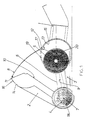
Die in der Fig. 1 in Form einer schematischen Strichzeichnung dargestellte aktive Staubsaugerdüse besteht aus einem mit einem Saugrohranschlußstutzen 1 versehenen zweiteiligen Gehäuse 2,3, in dem eine Bürstenwalze 4, ein Antrieb 5 und ein Getriebe 6 angeordnet sind. In dem hier gezeigten Ausführungsbeispiel der Staubsaugerdüse ist der Antrieb 5 als Turbine und das Getriebe 6 als Zahnriehmentrieb ausgebildet.The active vacuum cleaner nozzle shown in FIG. 1 in the form of a schematic line drawing consists of a two-
Das Gehäuseoberteil ist über ein in der Fig. 3 näher erläutertes Schwenklager koaxial zur Achse 7 der Bürstenwalze 4 am unteren Gehäuseteil 3 angelenkt.The upper housing part is articulated to the lower housing part 3 via a pivot bearing, which is explained in more detail in FIG. 3, coaxially to the
In der Fig. 1 ist das Gehäuseoberteil in einer mittleren Schwenkstellung dargestellt, also in einer teilweise geöffneten Stellung, die noch nicht der vollständigen Öffnung, aber auch nicht dem verriegelten Zustand entspricht.In Fig. 1, the upper housing part is shown in a central pivot position, that is, in a partially open position, which does not yet correspond to the full opening, but also does not correspond to the locked state.
Zum voliständigen Öffnung wird das Düsengehäuseoberteil 2 weiter in Richtung des Pfeils 8 verschwenkt und gibt dann in der schließlich mittels eines Anschlags definierten Endstellung den Innenraum des Düsengehäuses für einen Eingriff von oben mit alien seinen Funktionsteilen vollständig frei.For full opening, the upper part of the
Zum Verriegeln wird das Gehäuseoberteil 2 soweit entgegen der Richtung des Pfeils 8 verschwenkt, bis die gefalzte Unterkante 10 des Gehäuseoberteils auf der komplementär gefalzten Oberkante 9 des Gehäuseunterteils 3 flächenbündig eingreifend aufliegt. Bei dieser Schwenkbewegung schwenkt die saugrohranschlußstutzenseitige Stirnkante 11 des Gehäuseoberteils 2 frei an der bürstenwalzenseitigen Vorderkante 12 des nach Art eines Hohlzylindersegments ausgebildeten Lagerblocks 13 vorbei, und zwar bis zum Gehäusekantenanschlag gerade soweit, daß die zylindrische Außenfläche 14 gerade flächenbündig unter der komplementär zylindrischen Innenwandfläche 15 des Lagerblocks 13 des Saugrohranschlußstutzens 1 liegt. Zum Verriegeln des Gehäuseoberteils 2 auf dem Gehäuseunterteil 3 wird bei vollständig auf das Gehäuseunterteil 3 aufgeschwenktem Gehäuseoberteil 2 der Saugrohranschlußstutzen 1 in Richtung des Pfeiles 8 so verschwenkt, daß die zueinander komplementären Zylinderflächen 14 und 15 des Gehäuseoberteils 2 bzw. des Saugrohranschlußstutzens 1 flächenbündig aufeinander gleiten.To lock the
Um ein versehentlich oder unbemerktes und unbeabsichtigtes Entriegeln des Gehäuseoberteils 2 praktisch auszuschließen, ist auf der Zylinderfläche 14 des Gehäuseoberteils 2 eine vorspringende Querrippe 16 und eine auf der Zylindermantelfläche 15 des Saugrohranschlußstutzens 1 in gleicher Weise vorspringende Querrippe 15 ausgebildet, die zur Funktionsverdeutlichung in der Fig. 1 vergrößert und nicht maßstäblich dargestellt sind. Diese Querrippen 16,17 sind so dimensioniert, daß sie einerseits einen ausreichend wirksamen und deutlich spürbaren Anschlag und Druckpunkt im Übergangsbereich zwischen dem im Arbeitsmodus genutzten Schwenkwinkelbereich und dem das Gehäuseoberteil 2 entriegelnden Schwenkwinkelbereich des Saugrohranschlußstutzens 1 markieren, andererseits aber zerstörungsfrei federelastisch überwindbar sind.In order to practically exclude an inadvertent or unnoticed and unintentional unlocking of the
Die in den Figuren als Ausführungsbeispiel dargestellte Staubsaugerdüse läuft auf einem Paar vorderer Laufrollen 18 und einem Paar rückwärtiger Laufrollen 19. Dabei sind das Gehäuseoberteil 2, die Bürstenwalze 4 und die vorderern Laufrollen 18 koaxial zueinander um eine Schwenk- bzw. Rotationsachse 7 drehbar, während die Lagerzapfen für die rückwärtigen Laufrollen 19 und die Schwenklagerung für den Saugrohranschlußstutzen 1 ebenfalls koaxial auf einer Drehachse bzw. Schwenkachse 20 angeordnet sind.The vacuum cleaner nozzle shown as an exemplary embodiment in the figures runs on a pair of
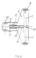
Diese koaxiale Anordnung der Funktionselemente ist insbesondere auch aus Fig. 2 gut ersichtlich.This coaxial arrangement of the functional elements can be seen particularly well from FIG. 2.
In der ebenfalls der Fig. 2 entnehmbaren Weise ist der Antrieb für die Bürstenwalze 4 in Form einer Zwillingsturbine mit einem rechten Turbinenlaufrad 5' und einem linken Turbinenlaufrad 5'' ausgebildet, die auf einer gemeinsamen Lagerwelle 21 laufen. Das von diesem Zwillingsturbinenantrieb 5' 5'' auf der Welle 21 abgreifbare Drehmoment wird über einen Gummizahnriehmen 22 von mittig zwischen den beiden Turbinenrädern 5' 5'' auf eine mittige Ankopplung 23 auf der Bürstenwalze 4 übertragen. Dabei ist der Zahnriementrieb 6 vollständig verkapselt in einem kanalartigen Getriebegehäuse 24 untergebracht, das horizontal zumindest im wesentlichen mittig getrennt und durch komplementäre Falze gedichtet mit seinem einen Teil integraler Bestandteil des Gehäuseunterteils 3 der Saugdüse, mit seinem oberen Teil integraler Bestandteil des Gehäuseoberteils 2 der Saugdüse ist.2, the drive for the
Das Gehäuseoberteil 2 ist in der aus der schematischen funktionserläuternden Fig. 3 ersichtlich über einen gleitsteinartig ausgebildeten Schwenkzapfen 25, der drehfest am Gehäuseunterteil 3 fixiert ist und eine offene Rundloch-Langloch-Kombination 26,27, die im Gehäuseoberteil 2 ausgebildet ist, so am Unterteil 3 angelenkt, daß das Gehäuseoberteil 2 in geöffneter Stellung frei vom Gehäuseunterteil 3 abziehbar ist.The
Claims (10)
- Active vacuum cleaner nozzle consisting of a two-piece housing (2,3) provided with a connection piece for a suction tube (1), within which housing is disposed a brushing roller (4), an actuation (5) and a gear system which transmits the torque taken-over from the actuation to the brushing roller, the two parts of the housing being detachably connected to each other such that the interior space of the housing is accessible to the user for cleaning purposes, the upper part of the housing (2) closing the interior space of the housing in a first detachably lockable position and releasing the brushing roller (4), the gear system (6) and the actuation in a second position,
characterized in
that the upper part of the housing (2) is detachably pivoted to the bottom part of the housing (3) and in that a swinging motion of the connection piece for the suction tube (1) is performable for the creation of the first locking position and the unlocking second position. - Vacuum cleaner nozzle according to claim 1,
characterized in
that the connection piece for the suction tube (1) is swingably connected to the bottom part of the housing (3) between the first position locking the upper part of the housing (2) and the second position unlocking the upper part of the housing (2), the unlocking position lying within a range of the pivoting angle necessary for the appropriate working mode of the connection piece for the suction tube (1). - Vacuum cleaner nozzle according to claim 2,
characterized by
a spring-elastically negotiable catch stopper (16,17) between the range of the pivoting angle of the connection piece for the suction tube (1) which is necessary for the appropriate working mode and the range of the pivoting angle unlocking the upper part of the housing (2). - Vacuum cleaner nozzle according to claim 2 or 3,
characterized in
that the housing-sided part of the connection piece for the suction tube (1), being adapted as drag bearing block (13) is adapted as a part of an actuation housing for the actuation (5) of the brushing roller (4) such that it overlapse the actuation at least partially within the range of pivoting angle of the working mode and uncovers the actuation within the unlocking range of pivoting angle. - Vacuum cleaner nozzle according to one of claims 1 to 4,
characterized by
a turbine as the actuation (5) for the brushing roller (4). - Vacuum cleaner nozzle according to claims 4 and 5,
characterized in
that the housing-sided drag bearing block (13) of the connection piece for the suction tube (1) is adapted as part of the turbine housing. - Vacuum cleaner nozzle according to one of claims 1 to 6,
characterized by
a pair of rollers (19) backwards of the connection piece for the suction tube and a pair of forward rollers (20), wherein the axles of rotation (7) of the forward rollers (18), the brushing roller (4) and the pivoting axle of the upper part of the housing (2) being disposed coaxially to each other. - Vacuum cleaner nozzle according to one of claims 1 to 7,
characterized in
that the gear system is a synchronous belt drive (6) which is coupled at the driving side centrally between two turbine wheels (5',5'') running on the shaft and at the driven side centrally on the brushing roller (4). - Vacuum cleaner nozzle according to claim 8,
characterized by
a two-piece gear system housing (24) wholly encapsulating the entire belt drive (6-22) as the suction tube housing (2,3) being closed, which gear system housing also wholly uncovering opens the belt drive during opening of the upper part of the suction nozzle housing. - Suction nozzle according to one of claims 1 to 9,
characterized in
that the drag bearing of the upper part of the housing of the nozzle housing is adapted with a bearing spigot (25) of a sliding block type and an open combination (26,27) of round hole - elongated hole - bearing hole such that the upper part of the housing (2) is detachable at the opening end of the range of the pivoting angle (3) from the bottom part of the housing (3).
Applications Claiming Priority (2)
| Application Number | Priority Date | Filing Date | Title |
|---|---|---|---|
| DE4121130 | 1991-06-26 | ||
| DE4121130A DE4121130A1 (en) | 1991-06-26 | 1991-06-26 | ACTIVE VACUUM CLEANER NOZZLE |
Publications (2)
| Publication Number | Publication Date |
|---|---|
| EP0520175A1 EP0520175A1 (en) | 1992-12-30 |
| EP0520175B1 true EP0520175B1 (en) | 1995-10-11 |
Family
ID=6434799
Family Applications (1)
| Application Number | Title | Priority Date | Filing Date |
|---|---|---|---|
| EP92108007A Expired - Lifetime EP0520175B1 (en) | 1991-06-26 | 1992-05-12 | Active vacuum cleaner nozzle |
Country Status (3)
| Country | Link |
|---|---|
| EP (1) | EP0520175B1 (en) |
| AT (1) | ATE128832T1 (en) |
| DE (2) | DE4121130A1 (en) |
Families Citing this family (4)
| Publication number | Priority date | Publication date | Assignee | Title |
|---|---|---|---|---|
| US5537710A (en) * | 1993-11-02 | 1996-07-23 | Rexair, Inc. | Cleaning tool having split manifold |
| DE19517700A1 (en) * | 1995-05-13 | 1996-11-14 | Vorwerk Co Interholding | Pick-up device for or with a brush for a floor cleaning device |
| US6513190B1 (en) | 2000-04-21 | 2003-02-04 | The Hoover Company | Turbine powered vacuum cleaner nozzle |
| CA2971505A1 (en) | 2015-12-10 | 2017-06-15 | Jiangsu Midea Cleaning Appliances Co., Ltd. | Floor brush assembly for upright vacuum cleaner and upright vacuum cleaner with the same |
Family Cites Families (4)
| Publication number | Priority date | Publication date | Assignee | Title |
|---|---|---|---|---|
| DE1243346B (en) * | 1959-03-06 | 1967-06-29 | Preco Inc | Air turbine for driving a cleaning tool in a vacuum cleaner mouthpiece |
| US4397060A (en) * | 1981-03-26 | 1983-08-09 | Black & Decker Inc. | Vacuum cleaner tool for use on horizontal and vertical surfaces |
| DE3879867T2 (en) * | 1987-10-23 | 1993-10-14 | Matsushita Electric Ind Co Ltd | Vacuum cleaner mouthpiece. |
| DE4000374A1 (en) * | 1989-01-31 | 1990-08-02 | Duepro Ag | MULTI-PURPOSE SUCTION NOZZLE |
-
1991
- 1991-06-26 DE DE4121130A patent/DE4121130A1/en not_active Withdrawn
-
1992
- 1992-05-12 DE DE59203957T patent/DE59203957D1/en not_active Expired - Fee Related
- 1992-05-12 EP EP92108007A patent/EP0520175B1/en not_active Expired - Lifetime
- 1992-05-12 AT AT92108007T patent/ATE128832T1/en not_active IP Right Cessation
Also Published As
| Publication number | Publication date |
|---|---|
| EP0520175A1 (en) | 1992-12-30 |
| ATE128832T1 (en) | 1995-10-15 |
| DE59203957D1 (en) | 1995-11-16 |
| DE4121130A1 (en) | 1993-01-07 |
Similar Documents
| Publication | Publication Date | Title |
|---|---|---|
| EP0526694B1 (en) | Active vacuum cleaner nozzle | |
| EP0321592B1 (en) | Hand-controlled sweeping apparatus | |
| DE69918564T2 (en) | CONSTRUCTION OF A VACUUM CLEANER | |
| DE69936861T2 (en) | CONNECTOR ASSEMBLY FOR VACUUM CLEANER BAG | |
| EP0277628B1 (en) | Suction cleaning apparatus | |
| EP0339323B1 (en) | Electric suction cleaner | |
| EP0280831A1 (en) | Filtering apparatus, in particular for vacuum cleaner | |
| EP0176696A2 (en) | Cleaning apparatus for dry or wet suction and/or for rinse extraction cleaning | |
| EP0289710B1 (en) | Filter bag arrangement in electric vacuum cleaners | |
| DE709147C (en) | vacuum cleaner | |
| EP0520175B1 (en) | Active vacuum cleaner nozzle | |
| EP0361240B1 (en) | Dust bag for a suction cleaner | |
| DE102010030731B4 (en) | vacuum cleaner nozzle | |
| DE3414862A1 (en) | Vacuum cleaner nozzle with suction tube connection, sliding sole and rotating brush cylinder | |
| EP4054393A1 (en) | Floor cleaning machine and method for operating a floor cleaning machine | |
| DE3520119A1 (en) | VACUUM CLEANER NOZZLE WITH ROTATING BRUSH | |
| WO2021204567A2 (en) | Filter unit for a cleaning machine, floor cleaning machine, and method for operating a floor cleaning machine | |
| DE19520778C1 (en) | Suction arrangement for street cleaner | |
| DE1124990B (en) | Street sweeper | |
| DE19821705A1 (en) | Suction device for sucking up dirt or the like | |
| EP0064161A1 (en) | Nozzle attachable to a junction pipe connected to a vacuum cleaner | |
| DE3723148A1 (en) | Suction cleaner disposal | |
| DE2721530C2 (en) | Brush attachment for a vacuum cleaner | |
| EP0441320A1 (en) | Vacuum cleaner nozzle with electrically driven brush | |
| EP3808241B1 (en) | Vacuum cleaning robot for autonomous cleaning of floor surfaces of a room |
Legal Events
| Date | Code | Title | Description |
|---|---|---|---|
| PUAI | Public reference made under article 153(3) epc to a published international application that has entered the european phase |
Free format text: ORIGINAL CODE: 0009012 |
|
| AK | Designated contracting states |
Kind code of ref document: A1 Designated state(s): AT DE ES FR GB IT NL SE |
|
| 17P | Request for examination filed |
Effective date: 19930624 |
|
| 17Q | First examination report despatched |
Effective date: 19940527 |
|
| GRAA | (expected) grant |
Free format text: ORIGINAL CODE: 0009210 |
|
| AK | Designated contracting states |
Kind code of ref document: B1 Designated state(s): AT DE ES FR GB IT NL SE |
|
| PG25 | Lapsed in a contracting state [announced via postgrant information from national office to epo] |
Ref country code: IT Free format text: LAPSE BECAUSE OF FAILURE TO SUBMIT A TRANSLATION OF THE DESCRIPTION OR TO PAY THE FEE WITHIN THE PRE;WARNING: LAPSES OF ITALIAN PATENTS WITH EFFECTIVE DATE BEFORE 2007 MAY HAVE OCCURRED AT ANY TIME BEFORE 2007. THE CORRECT EFFECTIVE DATE MAY BE DIFFERENT FROM THE ONE RECORDED.SCRIBED TIME-LIMIT Effective date: 19951011 Ref country code: GB Effective date: 19951011 Ref country code: ES Free format text: THE PATENT HAS BEEN ANNULLED BY A DECISION OF A NATIONAL AUTHORITY Effective date: 19951011 Ref country code: NL Free format text: LAPSE BECAUSE OF FAILURE TO SUBMIT A TRANSLATION OF THE DESCRIPTION OR TO PAY THE FEE WITHIN THE PRESCRIBED TIME-LIMIT Effective date: 19951011 Ref country code: FR Effective date: 19951011 |
|
| REF | Corresponds to: |
Ref document number: 128832 Country of ref document: AT Date of ref document: 19951015 Kind code of ref document: T |
|
| REF | Corresponds to: |
Ref document number: 59203957 Country of ref document: DE Date of ref document: 19951116 |
|
| PG25 | Lapsed in a contracting state [announced via postgrant information from national office to epo] |
Ref country code: SE Effective date: 19960111 |
|
| NLV1 | Nl: lapsed or annulled due to failure to fulfill the requirements of art. 29p and 29m of the patents act | ||
| EN | Fr: translation not filed | ||
| GBV | Gb: ep patent (uk) treated as always having been void in accordance with gb section 77(7)/1977 [no translation filed] |
Effective date: 19951011 |
|
| PG25 | Lapsed in a contracting state [announced via postgrant information from national office to epo] |
Ref country code: AT Effective date: 19960512 |
|
| PLBE | No opposition filed within time limit |
Free format text: ORIGINAL CODE: 0009261 |
|
| STAA | Information on the status of an ep patent application or granted ep patent |
Free format text: STATUS: NO OPPOSITION FILED WITHIN TIME LIMIT |
|
| 26N | No opposition filed | ||
| PGFP | Annual fee paid to national office [announced via postgrant information from national office to epo] |
Ref country code: DE Payment date: 20090630 Year of fee payment: 18 |
|
| PG25 | Lapsed in a contracting state [announced via postgrant information from national office to epo] |
Ref country code: DE Free format text: LAPSE BECAUSE OF NON-PAYMENT OF DUE FEES Effective date: 20101201 |