EP0526213A2 - Appareil pour séparer le bout d'une feuille avec un papier de support - Google Patents
Appareil pour séparer le bout d'une feuille avec un papier de support Download PDFInfo
- Publication number
- EP0526213A2 EP0526213A2 EP92306968A EP92306968A EP0526213A2 EP 0526213 A2 EP0526213 A2 EP 0526213A2 EP 92306968 A EP92306968 A EP 92306968A EP 92306968 A EP92306968 A EP 92306968A EP 0526213 A2 EP0526213 A2 EP 0526213A2
- Authority
- EP
- European Patent Office
- Prior art keywords
- sheet
- fixing
- separating
- tape
- separating device
- Prior art date
- Legal status (The legal status is an assumption and is not a legal conclusion. Google has not performed a legal analysis and makes no representation as to the accuracy of the status listed.)
- Granted
Links
Images


Classifications
-
- B—PERFORMING OPERATIONS; TRANSPORTING
- B29—WORKING OF PLASTICS; WORKING OF SUBSTANCES IN A PLASTIC STATE IN GENERAL
- B29C—SHAPING OR JOINING OF PLASTICS; SHAPING OF MATERIAL IN A PLASTIC STATE, NOT OTHERWISE PROVIDED FOR; AFTER-TREATMENT OF THE SHAPED PRODUCTS, e.g. REPAIRING
- B29C63/00—Lining or sheathing, i.e. applying preformed layers or sheathings of plastics; Apparatus therefor
- B29C63/0004—Component parts, details or accessories; Auxiliary operations
- B29C63/0013—Removing old coatings
-
- B—PERFORMING OPERATIONS; TRANSPORTING
- B26—HAND CUTTING TOOLS; CUTTING; SEVERING
- B26D—CUTTING; DETAILS COMMON TO MACHINES FOR PERFORATING, PUNCHING, CUTTING-OUT, STAMPING-OUT OR SEVERING
- B26D7/00—Details of apparatus for cutting, cutting-out, stamping-out, punching, perforating, or severing by means other than cutting
- B26D7/27—Means for performing other operations combined with cutting
-
- B—PERFORMING OPERATIONS; TRANSPORTING
- B65—CONVEYING; PACKING; STORING; HANDLING THIN OR FILAMENTARY MATERIAL
- B65H—HANDLING THIN OR FILAMENTARY MATERIAL, e.g. SHEETS, WEBS, CABLES
- B65H41/00—Machines for separating superposed webs
-
- Y—GENERAL TAGGING OF NEW TECHNOLOGICAL DEVELOPMENTS; GENERAL TAGGING OF CROSS-SECTIONAL TECHNOLOGIES SPANNING OVER SEVERAL SECTIONS OF THE IPC; TECHNICAL SUBJECTS COVERED BY FORMER USPC CROSS-REFERENCE ART COLLECTIONS [XRACs] AND DIGESTS
- Y10—TECHNICAL SUBJECTS COVERED BY FORMER USPC
- Y10S—TECHNICAL SUBJECTS COVERED BY FORMER USPC CROSS-REFERENCE ART COLLECTIONS [XRACs] AND DIGESTS
- Y10S83/00—Cutting
- Y10S83/929—Particular nature of work or product
- Y10S83/949—Continuous or wound supply
-
- Y—GENERAL TAGGING OF NEW TECHNOLOGICAL DEVELOPMENTS; GENERAL TAGGING OF CROSS-SECTIONAL TECHNOLOGIES SPANNING OVER SEVERAL SECTIONS OF THE IPC; TECHNICAL SUBJECTS COVERED BY FORMER USPC CROSS-REFERENCE ART COLLECTIONS [XRACs] AND DIGESTS
- Y10—TECHNICAL SUBJECTS COVERED BY FORMER USPC
- Y10T—TECHNICAL SUBJECTS COVERED BY FORMER US CLASSIFICATION
- Y10T156/00—Adhesive bonding and miscellaneous chemical manufacture
- Y10T156/19—Delaminating means
- Y10T156/1961—Severing delaminating means [e.g., chisel, etc.]
-
- Y—GENERAL TAGGING OF NEW TECHNOLOGICAL DEVELOPMENTS; GENERAL TAGGING OF CROSS-SECTIONAL TECHNOLOGIES SPANNING OVER SEVERAL SECTIONS OF THE IPC; TECHNICAL SUBJECTS COVERED BY FORMER USPC CROSS-REFERENCE ART COLLECTIONS [XRACs] AND DIGESTS
- Y10—TECHNICAL SUBJECTS COVERED BY FORMER USPC
- Y10T—TECHNICAL SUBJECTS COVERED BY FORMER US CLASSIFICATION
- Y10T225/00—Severing by tearing or breaking
- Y10T225/20—Severing by manually forcing against fixed edge
- Y10T225/257—Blade mounted on hand-held wound package
- Y10T225/259—With lead-end stripper for tacky adhesive work
Definitions
- the present invention relates to an end separating device for a sheet having a backing paper and, more particularly, to an end separating device for a sheet comprising a film and a backing paper superposed with respect to one another through an adhesive layer, wherein the backing paper is to be separated from the film at an end portion of the sheet so that the entire backing paper may be easily separated for use of the sheet.
- a sheet made by forming an adhesive layer on one surface of a film and attaching a backing paper to the adhesive layer is used in such a manner that the backing paper is separated from the film at an end portion of the sheet with fingers or the like, and then, the film thus separated is to be attached to various kinds of medium.
- a sheet is disclosed in U.S. Patent No. 4,927,278, for example.
- the former separating method such that the backing paper is separated from the film at the end portion of the sheet with fingers or the like, it is difficult to separate the backing paper from the film with the fingers because the film and the backing paper are closely attached to each other through the adhesive layer even at the end portion of the sheet. Further, there is a possibility that the end portion of the sheet is bent in the course of repetition of a separating operation, rendering the separation of the backing paper more difficult.
- the film can be easily separated from the backing paper because the film only is previously cut.
- an end separating device for a sheet consisting of a film and a backing paper superposed on each other through an adhesive layer, the end separating device comprising a sheet fixing and separating member for bending and fixing an end portion of the sheet having a predetermined length from an end of the sheet, and for separating the film from the backing paper at the end portion of the sheet against an adhesive strength of the adhesive layer.
- the end portion of the sheet having a predetermined length from the end of the sheet is bent and fixed by the sheet fixing and separating member, so that the film of the sheet is separated from the backing paper at the end portion of the sheet against the adhesive strength of the adhesive layer.
- an end separating device for a sheet consisting of a film and a backing paper superposed on each other through an adhesive layer
- the end separating device comprising a sheet fixing member for fixing an end portion of the sheet with a free end portion having a predetermined length from an end of the sheet being projected from an end surface of the sheet fixing member, and a separating member adapted to act on the free end portion of the sheet for separating the film from the backing paper at the free end portion against an adhesive strength of the adhesive layer.
- the end portion of the sheet is fixed by the sheet fixing member with the free end portion having a predetermined length from the end of the sheet being projected from the end surface of the fixing member. Then, the separating member is moved to act on the free end portion of the sheet, so that the film of the sheet is separated from the backing paper at the free end portion of the sheet against the adhesive strength of the adhesive layer.
- the film of the sheet can be easily separated from the backing paper at the end portion of the sheet.
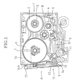
- Figs. 1 to 5 illustrate a first preferred embodiment according to the present invention applied to a tape printing device for making a printed tape T.
- the tape cassette 1 includes a tape spool 3 around which a transparent film tape 2 is wound, a ribbon spool 5 around which a thermal ink ribbon 4 is wound, and an adhesive tape spool 7 around which a double-sided adhesive tape 6 having a separable backing paper E is wound with the backing paper E forming an outer surface of the roll of the adhesive tape 6.
- These spools 3, 5 and 7 are rotatably supported within the tape cassette 1 in cooperation with respective supporting portions provided on a lower surface of the upper case (not shown).
- a ribbon take-up spool 8 is rotatably supported within the tape cassette 1 at a position among the spools 3, 5 and 7.
- the ribbon take-up spool 8 rotates with a ribbon take-up shaft (not shown), so that the thermal ink ribbon 4 used for printing is taken up around the ribbon take-up spool 8 by driving the ribbon take-up shaft.
- a pressure roller 12 and a tape feed roller 13 are rotatably supported in pressure contact with each other on the downstream side of the thermal head 10 along an advancing direction of the film tape 2 (i.e., at a left lower position as viewed in Fig. 1).
- the pressure roller 12 and the tape feed roller 13 function to feed the film tape 2, on which characters or the like have been printed through the thermal ink ribbon 4 by the thermal head 10, together with the double-sided adhesive tape 6 having the backing paper E, and bring both the tapes 2 and 6 into adhesion to each other in such a manner that a printed surface of the film tape 2 adheres to an adhesive surface of the adhesive tape 6 on the side opposite to the backing paper E.
- the printed tape T is finally ejected from a tape ejecting portion 14.
- the printed tape T thus prepared has a multilayer structure such that the printed film tape 2 and the backing paper E are separably bonded together through an adhesive layer D.
- a cutter mechanism 15 is provided in the vicinity of the tape ejecting portion 14, so as to suitably cut the tape T ejected from the tape ejecting portion 14.
- Fig. 2 is a side view of the cutter mechanism 15 taken in the direction of an arrow A shown in Fig. 1.
- a DC motor 16 is provided below a rear left portion of the tape cassette 1 as viewed in Fig. 1.
- a pinion 17 is fixed to a drive shaft 16A of the DC motor 16.
- An idle gear 18 is meshed with the pinion 17, and a rocking gear 19 is meshed with the idle gear 18.
- the pinion 17, the idle gear 18 and the rocking gear 19 constitute a gearing mechanism G.
- the idle gear 18 and the rocking gear 19 are rotatably supported on a side wall of the tape cassette 1.
- a rocking pin 20 is fixed to the rocking gear 19 at a position near the center of rotation thereof, and a sensor plate 21 is provided in the vicinity of a gear teeth portion of the rocking gear 19.
- a cutter sensor F is located outside the gear teeth portion of the rocking gear 19. The sensor plate 21 is detected by the cutter sensor F, thereby detecting a rotational position of the rocking gear 19 to control a drive starting position of a movable blade 22.
- the movable blade 22 is rotatably supported on a rotating shaft P.
- a rocking lever 23 is fixed to the movable blade 22 at the rotating shaft P.
- the rocking lever 23 is provided with a recess 23A, and the rocking pin 20 is inserted in the recess 23A.
- the movable blade 22 is adapted to be opened or closed relative to the fixed blade 24 with the rotating shaft P operating as a fulcrum.
- the movable blade 22 and the fixed blade 24 constitute a cutter K for cutting the tape T ejected from the tape ejecting portion 14.
- a fully open angle of the movable blade 22 relative to the fixed blade 24 is set to about 30 degrees in this preferred embodiment.
- reference numeral 30 designates a tape fixing and separating mechanism provided on the cutter K comprised of the movable blade 22 and the fixed blade 24.
- Fig. 3 is an enlarged side view of the cutter K
- Fig. 4 is a schematic sectional view illustrating a condition where the tape T is cut by the cutter K.
- the tape fixing and separating mechanism 30 is comprised of two fixing and separating members 30A and 30B.
- the first fixing and separating member 30A is fixed to an outer side surface of the movable blade 22 along a cutting edge thereof, while the second fixing and separating member 30B is fixed to an outer side surface of the fixed blade 24 along a cutting edge thereof.
- These fixing and separating members 30A and 30B cooperate to bend a cut end portion of the tape T by a given length several times and fix the cut end portion of the tape T in such a bent condition.
- the first fixing and separating member 30A is provided with a rightward projecting portion 31 and a leftward recessed portion 32 contiguous to each other.
- the projecting portion 31 and the recessed portion 32 have edges curved with a predetermined curvature so that when the tape T is fixed, it may be prevented from being unduly bent to be deformed or broken.
- the second fixing and separating member 30B is disposed in opposed relationship to the first fixing and separating member 30A so that a predetermined gap corresponding to a thickness of the tape T may be defined between the first and second fixing and separating members 30A and 30B when the tape T is fixed. That is, the second fixing and separating member 30B is provided with a recessed portion 34 mating with the projecting portion 31, a projecting portion 35 mating with the recessed portion 32, and a tapering portion 36 mating with the tapering cutting edge of the movable blade 22.
- the recessed portion 34 and the projecting portion 35 have edges curved for the same reason as that mentioned above.
- the fully open angle of the movable blade 22 relative to the fixed blade 24 is set to about 30 degrees as mentioned above.
- the movable blade 22 is movable relative to the fixed blade 24 in the angular range of 0 to 30 degrees in association with the opening or closing operation.
- the first fixing and separating member 30A fixed to the movable blade 22 is also movable relative to the second fixing and separating member 30B fixed to the fixed blade 24 in the angular range of 0 to 30 degrees.
- the DC motor 16 is driven to operate the cutter mechanism 15 in such a manner as mentioned above. Accordingly, the movable blade 22 is rotated toward the fixed blade 24. At the same time, the first fixing and separating member 30A is moved toward the second fixing and separating member 30B, and they cooperate to bend and fix the tape T. In this condition, the movable blade 22 and the fixed blade 24 cooperate to start cutting the tape T.
- the cut end portion of the tape T is fixed by the projecting portion 31 and the recessed portion 32 of the first fixing and separating member 30A and the recessed portion 34 and the projecting portion 35 of the second fixing and separating member 30B.
- the backing paper E of the tape T is plastically deformed at a portion T1 between the tapering portion 36 and a bent portion formed by the recessed portion 32 and the projecting portion 35.
- Such plastic deformation of the backing paper E is due to the fact that while the film tape 2 is strong in stiffness and can elastically restore an original condition from a bent condition, the backing paper E is weak in stiffness as compared with the film tape 2 and therefore tends to be plastically deformed at the portion T1. Accordingly, at the portion T1 of the tape T, the film tape 2 tends to be separated from the backing paper E against an adhesive strength of the adhesive layer D, starting from the cut end of the tape T. Further, at a portion T2 of the tape T fixed by the projecting portion 31 of the first fixing and separating member 30A and the recessed portion 34 of the second fixing and separating member 30B, the tape T is pressed by the projecting portion 31 from the film tape 2 side.
- the backing paper E is plastically deformed at the cut end portion of the tape T. Accordingly, when the tape T is released from the fixing and separating members 30A and 30B, the film tape 2 is separated from the backing paper E at the cut end portion of the tape T.
- the fixing and separating members 30A and 30B comprising the tape end separating device are fixed to the movable blade 22 and the fixed blade 24, respectively. Therefore, simultaneously with cutting of the tape T by means of the movable blade 22 and the fixed blade 24, the film tape 2 can be separated from the backing paper E at the cut end portion of the tape T. Accordingly, the tape end separating device can be manufactured with the reduced number of component parts at a low cost. Further, it is very convenient that the film tape 2 can be separated from the backing paper E at the cut end portion of the tape T every time the tape T is cut.
- the film tape 2 can be easily separated from the backing paper E.
- the fixing and separating members 30A and 30B are provided on the outer side surfaces of the movable blade 22 and the fixed blade 24, respectively, in respect of an ejecting direction of the tape T to be ejected from the tape ejecting portion 14 in the above preferred embodiment, it is to be noted that this arrangement is merely illustrative and not limitative.
- the fixing and separating members 30A and 30B may be provided on the inner side surfaces of the movable blade 22 and the fixed blade 24, respectively.
- Fig. 6 is a perspective view illustrating a condition where a sheet S having the backing paper E is fixed by a pair of sheet fixing members 41 and 42. As shown in Fig. 6, an end portion of the sheet S is fixedly sandwiched between the sheet fixing members 41 and 42 with a free end portion 40 having a predetermined length being projected from end surfaces of the sheet fixing members 41 and 42.
- the sheet S has a multilayer structure similar to that of the tape T shown in Fig. 5.
- the length of the free end portion 40 is set to about 1 mm in this preferred embodiment.
- FIGs. 6 to 9 there is only illustrated the concept of a mechanism for separating the film tape 2 from the backing paper E at a cut end portion of the sheet S cut by a conventional cutting mechanism.
- a separating member 43 is provided in such a manner that an angle a of the separating member 43 relative to the free end portion 40 is set to about 80 degrees.
- the separating member 43 is adapted to be moved in the direction of an arrow P in Fig. 8 by a suitable driving mechanism as maintaining the angle a at about 80 degrees.
- the sheet S is fixed by the sheet fixing members 41 and 42 with the free end portion 40 being projected from the end surfaces of the fixing members 41 and 42 as shown in Fig. 7.
- the separating member 43 is moved along the end surfaces of the fixing members 41 and 42 in the direction of the arrow P as maintaining the angle a to act on the free end portion 40 of the sheet S as shown in Fig. 8.
- the free end portion 40 of the sheet S is bent along the end surfaces of the sheet fixing members 41 and 42.
- the backing paper E only is plastically deformed at such a bent portion for the same reason as that mentioned in the first preferred embodiment.
- the film tape 2 is separated from the backing paper E at the free end portion 40 of the sheet S as shown in Fig. 9 by the operation similar to that of the first preferred embodiment.
- the end portion of the sheet S is fixed by the fixing members 41 and 42 with the free end portion 40 being projected from the end surfaces of the fixing members 41 and 42.
- the separating member 43 is moved as maintaining the angle a at about 80 degrees to act on the free end portion 40 of the sheet S. Accordingly, the film tape 2 can be separated from the backing paper E surely and smoothly.
- angle a of the separating member 43 relative to the free end portion 40 is set to about 80 degrees in the second preferred embodiment, it is to be noted that this value is merely illustrative and not limitative. That is, the value of the angle a may be suitably changed according to the stiffness of the film tape 2 and the backing paper E, the adhesive strength of the adhesive layer D, etc.
- a third preferred embodiment according to the present invention will be described with reference to Figs: 10 to 12.
- the same sheet S as that used in the second preferred embodiment is fixed by a pair of fixing members 51 and 52 with a free end portion 50 of the sheet S being projected from end surfaces of the fixing members 51 and 52.
- a separating member 53 is provided so as to be movable vertically relative to the free end portion 50 by means of a suitable driving mechanism.
- the separating mechanism in the third preferred embodiment is operated in the following manner. First, the sheet S is fixed by the fixing members 51 and 52 with the free end portion 50 being projected from the end surfaces of the fixing members 51 and 52 as shown in Fig. 10. Then, the separating member 53 is moved vertically (in the direction of an arrow Q in Fig. 11) along the end surfaces of the fixing members 51 and 52 to act on the free end portion 50 of the sheet S as shown in Fig. 11. As a result, the free end portion 50 is bent along the end surfaces of the fixing members 51 and 52 as shown in Fig. 12.
- the backing paper E only is plastically deformed at such a bent portion for the same reason as that mentioned in the first preferred embodiment, and resultantly, the film tape 2 is separated from the backing paper E at the free end portion 50 of the sheet S as shown in Fig. 12 by the operation similar to that of the second preferred embodiment.
- the film tape 2 can be separated from the backing paper E at the free end portion 50 of the sheet S surely and smoothly.
Applications Claiming Priority (2)
| Application Number | Priority Date | Filing Date | Title |
|---|---|---|---|
| JP217836/91 | 1991-08-02 | ||
| JP21783691A JP3611249B2 (ja) | 1991-08-02 | 1991-08-02 | 印刷装置 |
Publications (3)
| Publication Number | Publication Date |
|---|---|
| EP0526213A2 true EP0526213A2 (fr) | 1993-02-03 |
| EP0526213A3 EP0526213A3 (en) | 1993-06-09 |
| EP0526213B1 EP0526213B1 (fr) | 1997-09-24 |
Family
ID=16710517
Family Applications (1)
| Application Number | Title | Priority Date | Filing Date |
|---|---|---|---|
| EP92306968A Expired - Lifetime EP0526213B1 (fr) | 1991-08-02 | 1992-07-30 | Appareil pour séparer le bout d'une feuille avec un papier de support |
Country Status (4)
| Country | Link |
|---|---|
| US (1) | US5259681A (fr) |
| EP (1) | EP0526213B1 (fr) |
| JP (1) | JP3611249B2 (fr) |
| DE (1) | DE69222381T2 (fr) |
Cited By (7)
| Publication number | Priority date | Publication date | Assignee | Title |
|---|---|---|---|---|
| EP0634277A2 (fr) * | 1993-07-12 | 1995-01-18 | Esselte Dymo N.V. | Dispositif pour couper des bandes |
| EP0634276A2 (fr) * | 1993-07-12 | 1995-01-18 | Esselte Dymo N.V. | Appareil pour couper des bandes |
| US5458423A (en) * | 1992-06-11 | 1995-10-17 | Esselte Dymo N.V. | Tape cutting apparatus |
| EP0703151A3 (fr) * | 1994-09-06 | 1996-06-12 | King Jim Co Ltd | Dispositif pour détacher le bord d'une feuille pourvue d'un papier antiadhésif |
| US5538591A (en) * | 1992-04-21 | 1996-07-23 | Esselte Dymo N.V. | Tape cutting apparatus |
| WO1999054216A1 (fr) * | 1998-04-21 | 1999-10-28 | Esselte N.V. | Dispositif d'impression de bande et cassette pour bande |
| US6974270B2 (en) | 1997-08-22 | 2005-12-13 | Esselte | Tape printing device |
Families Citing this family (17)
| Publication number | Priority date | Publication date | Assignee | Title |
|---|---|---|---|---|
| US5395466A (en) * | 1992-07-07 | 1995-03-07 | Max Co., Ltd. | Back pasting apparatus and method |
| JP2629527B2 (ja) * | 1992-07-22 | 1997-07-09 | ブラザー工業株式会社 | テープ印字装置 |
| US5934812A (en) * | 1992-10-06 | 1999-08-10 | Seiko Epson Corp. | Tape printing device and tape cartridge used therein |
| CA2107746A1 (fr) * | 1992-10-06 | 1994-04-07 | Masahiko Nunokawa | Dispositif d'impression a ruban et cartouche de ruban pour ce dispositif |
| US5595447A (en) | 1992-10-13 | 1997-01-21 | Seiko Epson Corporation | Tape cartridge and printing device having print medium cartridge |
| DE4409819B4 (de) * | 1993-03-22 | 2004-08-05 | Kabushiki Kaisha Sato | Vorrichtung zum Vorwärtsbewegen eines Trägerstreifens |
| TW226004B (en) * | 1993-05-10 | 1994-07-01 | Siemens Nixdorf Inf Syst | A cutting device for cutting prints in the printing machine |
| GB9314386D0 (en) * | 1993-07-12 | 1993-08-25 | Esselte Dymo Nv | A cassette for a thermal printer |
| US5658416A (en) * | 1994-06-17 | 1997-08-19 | Polaroid Corporation | Method and apparatus for peeling a laminate |
| JP3644152B2 (ja) * | 1996-09-26 | 2005-04-27 | ブラザー工業株式会社 | テープ印字装置 |
| US5713679A (en) * | 1996-10-07 | 1998-02-03 | Monarch Marking Systems, Inc. | Apparatus for selectively dispensing liner-type and linerless-type labels |
| TW358059B (en) * | 1996-11-07 | 1999-05-11 | King Jim Co Ltd | Adhesive tape processing device |
| JP3628848B2 (ja) * | 1996-11-07 | 2005-03-16 | セイコーエプソン株式会社 | テープ処理装置およびこれを備えたテープ印刷装置 |
| JP2011121140A (ja) * | 2009-12-11 | 2011-06-23 | Seiko Epson Corp | カット装置及びこれを備えたテープ印刷装置 |
| US8298361B2 (en) * | 2009-12-16 | 2012-10-30 | Pitney Bowes Inc. | Postage label dispenser for dispensing application ready/lined labels including a re-lining station facilitating the fabrication of lined labels |
| JP5074562B2 (ja) * | 2010-07-29 | 2012-11-14 | 東芝テック株式会社 | カッターユニットおよびプリンタ |
| JP7098975B2 (ja) * | 2018-03-14 | 2022-07-12 | カシオ計算機株式会社 | 切断装置、テープ印刷装置、及び、切断方法 |
Citations (5)
| Publication number | Priority date | Publication date | Assignee | Title |
|---|---|---|---|---|
| US3530028A (en) * | 1964-10-27 | 1970-09-22 | Edwin E Messmer | Apparatus for peeling labels from a backing strip |
| GB2008028A (en) * | 1977-11-10 | 1979-05-31 | Brady Co W H | Separating laminated layers |
| EP0214461A2 (fr) * | 1985-09-12 | 1987-03-18 | Löhr & Herrmann GmbH | Dispositif pour enlever la feuille de protection d'un circuit imprimé recouvert d'une couche photorésistante exposée |
| EP0215397A2 (fr) * | 1985-09-05 | 1987-03-25 | Somar Corporation | Appareil pour peler une pellicule |
| EP0506257A1 (fr) * | 1991-03-12 | 1992-09-30 | Brother Kogyo Kabushiki Kaisha | Méthode et appareil pour séparer une feuille support d'une étiquette auto-collante |
Family Cites Families (8)
| Publication number | Priority date | Publication date | Assignee | Title |
|---|---|---|---|---|
| US3429761A (en) * | 1965-04-02 | 1969-02-25 | American Biltrite Rubber Co | Tape reclaiming device and process |
| US3985603A (en) * | 1975-06-16 | 1976-10-12 | Hobart Corporation | Method and apparatus for transportation of a label |
| US4312597A (en) * | 1977-11-06 | 1982-01-26 | Copal Company Limited | Printer |
| US4173510A (en) * | 1977-11-10 | 1979-11-06 | W. H. Brady Co. | Apparatus for separating laminated layers |
| US4173507A (en) * | 1977-11-15 | 1979-11-06 | W. H. Brady Co. | Separating laminated layers |
| US4177104A (en) * | 1977-11-14 | 1979-12-04 | W. H. Brady Co. | Apparatus for separating laminated layers |
| JPH0634126Y2 (ja) * | 1987-11-28 | 1994-09-07 | ブラザー工業株式会社 | 剥離紙付き印字テープ切断機構を備えた印字装置 |
| US4927278A (en) * | 1987-12-29 | 1990-05-22 | Brother Kogyo Kabushiki Kaisha | Tape cassette and tape printer for use therewith |
-
1991
- 1991-08-02 JP JP21783691A patent/JP3611249B2/ja not_active Expired - Fee Related
-
1992
- 1992-07-09 US US07/911,116 patent/US5259681A/en not_active Expired - Lifetime
- 1992-07-30 EP EP92306968A patent/EP0526213B1/fr not_active Expired - Lifetime
- 1992-07-30 DE DE69222381T patent/DE69222381T2/de not_active Expired - Fee Related
Patent Citations (5)
| Publication number | Priority date | Publication date | Assignee | Title |
|---|---|---|---|---|
| US3530028A (en) * | 1964-10-27 | 1970-09-22 | Edwin E Messmer | Apparatus for peeling labels from a backing strip |
| GB2008028A (en) * | 1977-11-10 | 1979-05-31 | Brady Co W H | Separating laminated layers |
| EP0215397A2 (fr) * | 1985-09-05 | 1987-03-25 | Somar Corporation | Appareil pour peler une pellicule |
| EP0214461A2 (fr) * | 1985-09-12 | 1987-03-18 | Löhr & Herrmann GmbH | Dispositif pour enlever la feuille de protection d'un circuit imprimé recouvert d'une couche photorésistante exposée |
| EP0506257A1 (fr) * | 1991-03-12 | 1992-09-30 | Brother Kogyo Kabushiki Kaisha | Méthode et appareil pour séparer une feuille support d'une étiquette auto-collante |
Non-Patent Citations (5)
| Title |
|---|
| EP-A- 0 214 461 * |
| EP-A- 0 215 397 * |
| EP-A- 0 506 257 * |
| GB-A- 2 008 028 * |
| US-A- 3 530 028 * |
Cited By (14)
| Publication number | Priority date | Publication date | Assignee | Title |
|---|---|---|---|---|
| US5538591A (en) * | 1992-04-21 | 1996-07-23 | Esselte Dymo N.V. | Tape cutting apparatus |
| US5458423A (en) * | 1992-06-11 | 1995-10-17 | Esselte Dymo N.V. | Tape cutting apparatus |
| EP0634276A3 (fr) * | 1993-07-12 | 1995-08-30 | Esselte Dymo Nv | Appareil pour couper des bandes. |
| EP0634277A2 (fr) * | 1993-07-12 | 1995-01-18 | Esselte Dymo N.V. | Dispositif pour couper des bandes |
| EP0634277A3 (fr) * | 1993-07-12 | 1995-08-30 | Esselte Dymo Nv | Dispositif pour couper des bandes. |
| EP0634276A2 (fr) * | 1993-07-12 | 1995-01-18 | Esselte Dymo N.V. | Appareil pour couper des bandes |
| US5569354A (en) * | 1993-07-12 | 1996-10-29 | Esselte N.V. | Tape cutting apparatus |
| EP0703151A3 (fr) * | 1994-09-06 | 1996-06-12 | King Jim Co Ltd | Dispositif pour détacher le bord d'une feuille pourvue d'un papier antiadhésif |
| US5653850A (en) * | 1994-09-06 | 1997-08-05 | King Jim Co., Ltd. | Device for peeling off edge portion of sheet provided with released paper |
| EP0835812A1 (fr) * | 1994-09-06 | 1998-04-15 | King Jim Co., Ltd. | Dispositif pour détacher le bord d'une feuille pourvue d'un papier anti-adhésif |
| US5843276A (en) * | 1994-09-06 | 1998-12-01 | King Jim Co., Ltd. | Device for peeling off edge portion of sheet provided with release paper |
| US6974270B2 (en) | 1997-08-22 | 2005-12-13 | Esselte | Tape printing device |
| WO1999054216A1 (fr) * | 1998-04-21 | 1999-10-28 | Esselte N.V. | Dispositif d'impression de bande et cassette pour bande |
| US6435744B1 (en) | 1998-04-21 | 2002-08-20 | Esselte N.V. | Tape printing device and tape cassette |
Also Published As
| Publication number | Publication date |
|---|---|
| DE69222381T2 (de) | 1998-02-26 |
| US5259681A (en) | 1993-11-09 |
| EP0526213A3 (en) | 1993-06-09 |
| JP3611249B2 (ja) | 2005-01-19 |
| DE69222381D1 (de) | 1997-10-30 |
| EP0526213B1 (fr) | 1997-09-24 |
| JPH0539165A (ja) | 1993-02-19 |
Similar Documents
| Publication | Publication Date | Title |
|---|---|---|
| US5259681A (en) | End separating device for sheet having a backing paper | |
| US4328066A (en) | Tape splicing apparatus | |
| JP6011120B2 (ja) | シートカートリッジ、ラベル作成装置およびラベル作成装置の制御方法 | |
| US5066152A (en) | Recording apparatus with mechanism for cutting printed tape covered by backing tape | |
| EP0555954B1 (fr) | Cassette à bande | |
| US5271789A (en) | Tape end processing unit | |
| JPH06227102A (ja) | テープ巻取り機構 | |
| US5117719A (en) | End trimming mechanism of tape printer | |
| EP0158183B1 (fr) | Dispositif de coupage de bandes de film | |
| JP3448263B2 (ja) | テープカセット | |
| US5843276A (en) | Device for peeling off edge portion of sheet provided with release paper | |
| US5254200A (en) | Method and apparatus for peeling a releasable sheet from an adhesive label | |
| JPH0592629A (ja) | 切断装置 | |
| JP3833784B2 (ja) | ラベルプリンタのカッターユニット | |
| EP0841181B1 (fr) | Dispositif pour séparer, dispositif de traitement de ruban comprenant le dispositif pour séparer et dispositif d'impression de ruban contenant le dispositif de traitement du ruban | |
| US20200406640A1 (en) | Cutter unit selectively performing one of full-cutting and half-cutting, and printer including the same | |
| JPH0585664A (ja) | 剥離紙を有するシートの端部剥離装置 | |
| JP3530541B2 (ja) | カッター機構 | |
| JP2005053177A (ja) | テープ印字装置 | |
| JP2606462B2 (ja) | テープカートリッジ | |
| US11760114B2 (en) | Printer and blade unit | |
| JPH05185679A (ja) | テープカセット | |
| WO1984000324A1 (fr) | Dispositif d'avance de feuille pour enregistreur | |
| US11760115B2 (en) | Tape cassette having conveying passage for conveying tape | |
| JP2004352509A (ja) | 剥離シートを有するシートの端部剥離装置 |
Legal Events
| Date | Code | Title | Description |
|---|---|---|---|
| PUAI | Public reference made under article 153(3) epc to a published international application that has entered the european phase |
Free format text: ORIGINAL CODE: 0009012 |
|
| AK | Designated contracting states |
Kind code of ref document: A2 Designated state(s): BE DE FR GB |
|
| PUAL | Search report despatched |
Free format text: ORIGINAL CODE: 0009013 |
|
| AK | Designated contracting states |
Kind code of ref document: A3 Designated state(s): BE DE FR GB |
|
| 17P | Request for examination filed |
Effective date: 19930903 |
|
| 17Q | First examination report despatched |
Effective date: 19950419 |
|
| GRAG | Despatch of communication of intention to grant |
Free format text: ORIGINAL CODE: EPIDOS AGRA |
|
| GRAH | Despatch of communication of intention to grant a patent |
Free format text: ORIGINAL CODE: EPIDOS IGRA |
|
| GRAH | Despatch of communication of intention to grant a patent |
Free format text: ORIGINAL CODE: EPIDOS IGRA |
|
| GRAA | (expected) grant |
Free format text: ORIGINAL CODE: 0009210 |
|
| AK | Designated contracting states |
Kind code of ref document: B1 Designated state(s): BE DE FR GB |
|
| ET | Fr: translation filed | ||
| REF | Corresponds to: |
Ref document number: 69222381 Country of ref document: DE Date of ref document: 19971030 |
|
| PLBE | No opposition filed within time limit |
Free format text: ORIGINAL CODE: 0009261 |
|
| STAA | Information on the status of an ep patent application or granted ep patent |
Free format text: STATUS: NO OPPOSITION FILED WITHIN TIME LIMIT |
|
| 26N | No opposition filed | ||
| REG | Reference to a national code |
Ref country code: GB Ref legal event code: IF02 |
|
| PGFP | Annual fee paid to national office [announced via postgrant information from national office to epo] |
Ref country code: DE Payment date: 20070726 Year of fee payment: 16 |
|
| PGFP | Annual fee paid to national office [announced via postgrant information from national office to epo] |
Ref country code: GB Payment date: 20070725 Year of fee payment: 16 |
|
| PGFP | Annual fee paid to national office [announced via postgrant information from national office to epo] |
Ref country code: BE Payment date: 20071004 Year of fee payment: 16 |
|
| PGFP | Annual fee paid to national office [announced via postgrant information from national office to epo] |
Ref country code: FR Payment date: 20070710 Year of fee payment: 16 |
|
| GBPC | Gb: european patent ceased through non-payment of renewal fee |
Effective date: 20080730 |
|
| PG25 | Lapsed in a contracting state [announced via postgrant information from national office to epo] |
Ref country code: DE Free format text: LAPSE BECAUSE OF NON-PAYMENT OF DUE FEES Effective date: 20090203 |
|
| REG | Reference to a national code |
Ref country code: FR Ref legal event code: ST Effective date: 20090331 |
|
| PG25 | Lapsed in a contracting state [announced via postgrant information from national office to epo] |
Ref country code: GB Free format text: LAPSE BECAUSE OF NON-PAYMENT OF DUE FEES Effective date: 20080730 |
|
| PG25 | Lapsed in a contracting state [announced via postgrant information from national office to epo] |
Ref country code: FR Free format text: LAPSE BECAUSE OF NON-PAYMENT OF DUE FEES Effective date: 20080731 |
|
| PG25 | Lapsed in a contracting state [announced via postgrant information from national office to epo] |
Ref country code: BE Free format text: LAPSE BECAUSE OF NON-PAYMENT OF DUE FEES Effective date: 20080731 |