EP0523410A2 - Wiedergabeanordnung für Basstöne im Kraftfahrzeug - Google Patents
Wiedergabeanordnung für Basstöne im Kraftfahrzeug Download PDFInfo
- Publication number
- EP0523410A2 EP0523410A2 EP19920110617 EP92110617A EP0523410A2 EP 0523410 A2 EP0523410 A2 EP 0523410A2 EP 19920110617 EP19920110617 EP 19920110617 EP 92110617 A EP92110617 A EP 92110617A EP 0523410 A2 EP0523410 A2 EP 0523410A2
- Authority
- EP
- European Patent Office
- Prior art keywords
- armrest
- display device
- box
- housing
- subwoofer
- Prior art date
- Legal status (The legal status is an assumption and is not a legal conclusion. Google has not performed a legal analysis and makes no representation as to the accuracy of the status listed.)
- Granted
Links
- 230000011514 reflex Effects 0.000 claims description 16
- 238000005192 partition Methods 0.000 claims description 6
- 238000003780 insertion Methods 0.000 claims description 2
- 230000037431 insertion Effects 0.000 claims description 2
- 239000002184 metal Substances 0.000 claims description 2
- 239000002918 waste heat Substances 0.000 claims description 2
- 230000005540 biological transmission Effects 0.000 description 3
- 230000001771 impaired effect Effects 0.000 description 3
- 238000001816 cooling Methods 0.000 description 2
- 230000015572 biosynthetic process Effects 0.000 description 1
- 238000011161 development Methods 0.000 description 1
- 230000018109 developmental process Effects 0.000 description 1
- 230000000694 effects Effects 0.000 description 1
- 238000009434 installation Methods 0.000 description 1
- 239000012528 membrane Substances 0.000 description 1
- 230000000149 penetrating effect Effects 0.000 description 1
- 230000005855 radiation Effects 0.000 description 1
- 230000005236 sound signal Effects 0.000 description 1
- 238000001228 spectrum Methods 0.000 description 1
Images
Classifications
-
- H—ELECTRICITY
- H04—ELECTRIC COMMUNICATION TECHNIQUE
- H04R—LOUDSPEAKERS, MICROPHONES, GRAMOPHONE PICK-UPS OR LIKE ACOUSTIC ELECTROMECHANICAL TRANSDUCERS; DEAF-AID SETS; PUBLIC ADDRESS SYSTEMS
- H04R1/00—Details of transducers, loudspeakers or microphones
- H04R1/20—Arrangements for obtaining desired frequency or directional characteristics
- H04R1/22—Arrangements for obtaining desired frequency or directional characteristics for obtaining desired frequency characteristic only
- H04R1/28—Transducer mountings or enclosures modified by provision of mechanical or acoustic impedances, e.g. resonator, damping means
- H04R1/2807—Enclosures comprising vibrating or resonating arrangements
- H04R1/2838—Enclosures comprising vibrating or resonating arrangements of the bandpass type
- H04R1/2842—Enclosures comprising vibrating or resonating arrangements of the bandpass type for loudspeaker transducers
-
- B—PERFORMING OPERATIONS; TRANSPORTING
- B60—VEHICLES IN GENERAL
- B60R—VEHICLES, VEHICLE FITTINGS, OR VEHICLE PARTS, NOT OTHERWISE PROVIDED FOR
- B60R11/00—Arrangements for holding or mounting articles, not otherwise provided for
- B60R11/02—Arrangements for holding or mounting articles, not otherwise provided for for radio sets, television sets, telephones, or the like; Arrangement of controls thereof
- B60R11/0217—Arrangements for holding or mounting articles, not otherwise provided for for radio sets, television sets, telephones, or the like; Arrangement of controls thereof for loud-speakers
-
- H—ELECTRICITY
- H04—ELECTRIC COMMUNICATION TECHNIQUE
- H04R—LOUDSPEAKERS, MICROPHONES, GRAMOPHONE PICK-UPS OR LIKE ACOUSTIC ELECTROMECHANICAL TRANSDUCERS; DEAF-AID SETS; PUBLIC ADDRESS SYSTEMS
- H04R1/00—Details of transducers, loudspeakers or microphones
- H04R1/02—Casings; Cabinets ; Supports therefor; Mountings therein
- H04R1/025—Arrangements for fixing loudspeaker transducers, e.g. in a box, furniture
-
- B—PERFORMING OPERATIONS; TRANSPORTING
- B60—VEHICLES IN GENERAL
- B60R—VEHICLES, VEHICLE FITTINGS, OR VEHICLE PARTS, NOT OTHERWISE PROVIDED FOR
- B60R11/00—Arrangements for holding or mounting articles, not otherwise provided for
- B60R2011/0001—Arrangements for holding or mounting articles, not otherwise provided for characterised by position
- B60R2011/0003—Arrangements for holding or mounting articles, not otherwise provided for characterised by position inside the vehicle
- B60R2011/0012—Seats or parts thereof
- B60R2011/0014—Arm-rests
Definitions
- the invention is concerned with the reproduction of low-frequency tones in the motor vehicle, in particular in passenger vehicles.
- the transducers are arranged in essentially closed loudspeaker boxes in order to achieve a good sound image or high-quality sound reproduction.
- the resonance structure of air volume and acoustic mass of an additional radiation opening arranged in the housing should act as a phase rotator in a certain frequency range, and that Summation of the energy radiated from the front and back of the membrane.
- the loudspeaker is inserted in the partition dividing the housing of the loudspeaker into two differently sized or equally large volumes. Sound is emitted through an opening that connects one of the two volumes to the environment.
- This loudspeaker arrangement which is also known as the double chamber principle, is characterized in that the loudspeaker is completely surrounded by the loudspeaker housing and thus does not - like the bass reflex boxes - require external surfaces which are dimensionally capable of accommodating the large bass loudspeakers. Since a Helmholtz resonator has a 2nd order bandpass transmission behavior and the useful sound of the double chamber box consists only of the sound emitted by the bass reflex channel, an acoustic filter effect is achieved by this arrangement.
- double chamber boxes are made significantly smaller than bass reflex boxes with the same sound quality.
- the loudspeaker used in the partition is designed as a double-coil loudspeaker.
- the common reproduction of bass signals by means of a subwoofer box is possible because such boxes are decoupled with a low-pass filter with a very low cut-off frequency.
- the result of the low decoupling is that the human ear in this frequency range is no longer able to locate the source which emits this low-frequency sound. Since the double chamber box already has a 2nd order bass pass transmission characteristic, the decoupling is very effective even with simple filters.
- the subwoofer boxes also need a certain minimum volume for acceptable sound reproduction. According to the applicant's knowledge, this is at least seven liters. However, this minimum space requirement is hardly available in the interior of modern passenger cars. For this reason, at some automobile manufacturers, if subwoofer boxes are to be used in the motor vehicle, they are arranged in the trunk and the sound outlet openings are led into the interior of the passenger compartment. In addition to the fact that the guidance of the sound outlet openings from the trunk into the interior of the vehicle is very complex, it is generally considered disadvantageous to reduce the size of the trunk by installing additional components, such as the subwoofer boxes.
- This object is achieved in that the subwoofer box can be used completely in the armrest of a passenger car.
- the amplifier for the bass loudspeaker of the subwoofer box is arranged inside the box housing. This measure allows conventional armrests to be replaced very quickly with armrests equipped with subwoofer boxes, since the operation of subwoofer armrest boxes is only operable by connecting the supply line to the amplifier with the signal source.
- the bass reflex channel is simultaneously designed as a cooling section for the amplifier, the waste heat of the amplifier is dissipated by the air moving in the bass reflex channel.
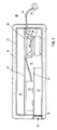
- the outer contours of the subwoofer box 10 shown in section in FIG. 1 are formed by the housing 11.
- the Housing 11 with a total internal volume of eight liters is completely covered on the outside with the padding 12.
- the outer contour of the subwoofer armrest box can be adapted to the space available in different motor vehicles in a very simple manner by means of a differently thick padding 12 without the housing 11 of the box itself being changed.
- the interior of the housing 11 is divided into a closed volume 14 and a bass reflex volume 15 by means of the partition wall 13.
- Partition 13 is provided with an opening 16.
- the bass loudspeaker 17 is inserted into this opening 16 in such a way that the inner contour 18 of the loudspeaker diaphragm 19 points to the closed volume 14.
- the wall 22 of this channel 21 is formed from sheet metal and thus serves the amplifier 23 arranged on it as a cooling section.
- the contacting of the amplifier 23 takes place via the cable harness 24 and the connector 25.
- the connector 25 in particular enables quick contacting if motor vehicles are to be retrofitted with the subwoofer armrest box, because in this case the existing armrest is only replaced by one for the operation of the subwoofer armrest box Subwoofer armrest box and contacting the connector 25 required.
- the contact between amplifier 23 and loudspeaker 19 has not been shown.
- the sound outlet opening 20 is provided with a grille 26, which permanently prevents objects from penetrating into the interior of the housing 11.
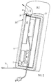
- the subwoofer armrest box shown in FIG. 1 is inserted into the insertion opening 27 of the seat element shown in the detail.
- the bass reflex channel 21 runs approximately parallel to the plane 28.1 of the backrest element 28.2.
- the backrest element 28.2 has a shape 30 in the region of the mouth 29 of the bass reflex channel 21, the sound quality of the box is not impaired.
- the formation 30 allows sound to emerge from the bass reflex tube 21 along the arrow into the interior of the motor vehicle.
- Position 31 marks the pivot point of the subwoofer armrest box. If the armrest box is lowered around the pivot point 31 with the side 32 onto the seat surface 33, the sound outlet opening 20 points in the direction of the dashboard of the motor vehicle. This position of the subwoofer armrest box has not been shown in FIG. 2 for reasons of clarity.
- the box can be used as a subwoofer armrest box by a differently thick padding 12 for a large number of different passenger cars.
Landscapes
- Engineering & Computer Science (AREA)
- Physics & Mathematics (AREA)
- Acoustics & Sound (AREA)
- Signal Processing (AREA)
- Mechanical Engineering (AREA)
- Health & Medical Sciences (AREA)
- Otolaryngology (AREA)
- Fittings On The Vehicle Exterior For Carrying Loads, And Devices For Holding Or Mounting Articles (AREA)
- Details Of Audible-Bandwidth Transducers (AREA)
- Chair Legs, Seat Parts, And Backrests (AREA)
Abstract
Description
- Die Erfindung befaßt sich mit der Wiedergabe von tieffrequenten Tönen im Kraftfahrzeug, insbesondere in Personenkraftfahrzeugen.
- Sollen tiefe und sehr tiefe Tonfrequenzen mittels elektroakustischer Wandler übertragen werden, werden die Wandler zur Erreichung eines guten Klangbildes bzw. einer hochwertigen Schallwiedergabe in im wesentlichen geschlossenen Lautsprecherboxen angeordnet.
- In diesem Zusammenhang sei zunächst auf die allseitig bekannte Baßreflexbox hingewiesen. Bei diesem Boxentyp, bei dem der Lautsprecher derart in der Außenfläche des Lautsprechergehäuses eingebaut ist, daß er direkt in das Volumen der Umgebung abstrahlt, soll das Resonanzgebilde aus Luftvolumen und akustischer Masse einer zusätzlichen im Gehäuse angeordneten Abstrahlöffnung in einem bestimmten Frequenzbereich als Phasendreher wirken und die Summatation der von der Membranvorderseite und der Membranrückseite abgestrahlten Energie bewirken.
- Des weiteren sind auch Anordnungen bekannt, bei denen der Lautsprecher in der das Gehäuse der Lautsprecherbox in zwei verschieden große oder auch gleich große Volumina unterteilenden Trennwand eingesetzt ist. Die Schallabstrahlung erfolgt durch eine Öffnung, welche eines der beiden Volumina mit der Umgebung verbindet. Diese Lautsprecheranordnung, welche auch als Doppelkammerprinzip bekannt ist, zeichnet sich dadurch aus, daß der Lautsprecher völlig von dem Lautsprechergehäuse umgeben ist und somit nicht - wie die Baßreflexboxen - Außenflächen erfordert, die von ihren Abmessungen her in der Lage sind, die großen Baßlautsprecher aufzunehmen. Da ein Helmholtz-Resonator ein Bandpassübertragungsverhalten 2. Ordnung besitzt und der Nutzschall der Doppelkammerbox nur aus dem von dem Baßreflexkanal abgestrahlten Schall besteht, wird durch diese Anordnung eine akustische Filterwirkung erzielt. Durch entsprechend Dimensionierung (vergl. etwa den Aufsatz von L. R. Fincham; KEF Electronics Limited, Maidstone-England, mit dem Titel: A Bandpass Loudspeaker Enclosure) der beiden Volumina und deren Verhältnis zueinander kann in Verbindung mit einem geeigneten Lautsprecher eine sehr tiefe und in bestimmten Grenzen beliebig breitbandige Abstimmung erfolgen. Mit anderen Worten, es kann allein durch die Abstimmung der beiden verschiedenen Resonanzfrequenzen einer solchen Box die Baßübertragung auf ein außerordentlich niedriges Frequenzspektrum beschränkt werden.
- Ein weiterer Vorteil von Doppelkammerboxen ist es, daß sie bei gleicher Klangqualität gegenüber Baßreflexboxen wesentlich kleiner ausgebildet werden können. Bei Einsatz von Subwoofern kann bei stereotoner Wiedergabe von Tonsignalen sogar auf die Ausstattung eines jeden Kanals mit einer separaten Baßbox verzichtet werden, wenn der in der Trennwand eingesetzte Lautsprecher als Doppelspulenlautsprecher ausgebildet wird. Die gemeinsame Wiedergabe von Baßsignalen mittels einer Subwooferbox ist deshalb möglich, da derartige Boxen mit einem Tiefpaßfilter mit sehr tiefer Grenzfrequenz abgekoppelt werden. Die niedrige Abkopplung hat zur Folge, daß das menschliche Gehör in diesem Frequenzbereich nicht mehr in der Lage ist, die diesen niederfrequenten Ton aussendende Quelle zu lokalisieren. Da die Doppelkammerbox bereits akustisch eine Baßpaßübertragungscharakteristik 2.Ordnung aufweist, ist die Abkopplung auch mit einfachen Filtern sehr wirkungsvoll möglich.
- Ebenso wie die Baßreflexboxen benötigen auch die Subwooferboxen zu einer akzeptablen Schallwiedergabe ein bestimmtes Mindestvolumen. Dieses liegt nach Erkenntnissen der Anmelderin bei mindestens sieben Litern. Dieser Mindestraumbedarf ist aber in Innenräumen von modernen Personenkraftwagen kaum verfügbar. Aus diesem Grunde werden bei einigen Automobilherstellern, wenn Subwooferboxen im Kraftfahrzeug eingesetzt werden sollen, diese im Kofferraum angeordnet und die Schallaustrittsöffnungen ins Innere des Fahrgastraumes geführt. Abgesehen davon, daß die Führung der Schallaustrittsöffnungen vom Kofferraum in den Innenraum des Fahrzeuges sehr aufwendig ist, wird es allgemein auch als nachteilig angesehen, den Kofferraum durch den Einbau von zusätzlichen Bauteilen - wie etwa die Subwooferboxen - zu verkleinern.
- Weiterhin sind Anordnungen bekannt, die angeben, die Subwooferboxen unterhalb der Vordersitze anzuordnen. Diese Position im Inneren der Fahrgastzelle von Personenkraftwagen ist aber nur bedingt ausnutzbar. Oftmals ist dieser Raum schon mit Stellmotoren für die elektrische Sitzverstellung belegt. Aber auch dann, wenn trotz der Stellmotoren für die Sitzverstellung noch Platz für eine Boxenanordnung verbleibt, sind dann für jeden PKW-Hersteller bzw. PKW-Typ unterschiedliche Boxengehäuse auszubilden, um den individuell verbleibenden Platz optimal auszunutzen. Daher liegt der Erfindung die Aufgabe zugrunde, eine Wiedergabeanordnung für Baßtöne anzugeben, die nach dem Subwooferprinzip arbeitet und die im Inneren eines Personenkraftwagens einsetzbar ist, wobei diese Box für eine Vielzahl verschiedener Personenkraftwagen standardisiert ist.
- Diese Aufgabe wird dadurch gelöst, daß die Subwooferbox vollständig in der Armlehne eines Personenkraftwagens einsetzbar ist.
- Besonders gute Klangergebnisse werden erzielt, wenn - wie in Anspruch 2 angegeben - die Schallaustrittsöffnung der Subwooferbox im ausgeklappten Zustand der Armlehne in Richtung zum Armaturenbrett des Fahrzeuges weist. Die Baßwiedergabe durch die in der Armlehne integrierte Subwooferbox wird nicht durch ein Einklappen der Armlehne in die Einbauöffnung beeinträchtigt, wenn - gemäß Anspruch 3 - das Sitzelement, welches die Armlehne aufnehmen soll, so ausgebildet ist, daß es bei hochgeklappter Armlehne die Schallaustrittsöffnung weder verdeckt noch verschließt.
- Weitere vorteilhafte Ausbildungen der Erfindung sind in den Ansprüchen 4 bis 6 angegeben.
- Ganz besonders vorteilhaft ist, wenn der Verstärker für den Baßlautsprecher der Subwooferbox innerhalb des Boxengehäuses angeordnet ist. Durch diese Maßnahme lassen sich herkömmliche Armlehnen sehr schnell durch mit Subwooferboxen ausgestattete Armlehnen ersetzen, da zum Betrieb von Subwooferarmlehnenboxen diese allein durch die Verbindung der Zuleitung zum Verstärker mit der Signalquelle betriebsfähig sind.
- Ist der Baßreflexkanal gleichzeitig als Kühlstrecke für den Verstärker ausgebildet, wird die Abwärme des Verstärkers durch die im Baßreflexkanal bewegte Luft abgeführt.
- Es zeigen:
- Figur 1
- eine in der Armlehne eines Personenkraftwagens integrierte Subwooferbox im Schnitt; und
- Figur 2
- die in Figur 1 gezeigte Armlehnenbox, wobei diese Box in das Sitzelement eingeklappt ist.
- Die Erfindung soll nun anhand der beiden Figuren näher erläutert werden.
- Die Außenkonturen der in Figur 1 im Schnitt dargestellten Subwooferbox 10 werden von dem Gehäuse 11 gebildet. Das Gehäuse 11 mit einem Gesamtinnenvolumen von acht Litern ist auf der Außenseite vollständig mit der Polsterung 12 ummantelt. Durch eine verschieden dicke Polsterung 12 kann die Außenkontur der Subwooferarmlehnenbox in sehr einfacher Weise dem Raumangebot in verschiedenen Kraftfahrzeugen angepaßt werden, ohne daß das Gehäuse 11 der Box selbst verändert wird.
- Das Innere des Gehäuses 11 ist mittels der Trennwand 13 in ein geschlossenes Volumen 14 und ein Baßreflexvolumen 15 unterteilt. Trennwand 13 ist mit einer Öffnung 16 versehen. In diese Öffnung 16 ist der Baßlautsprecher 17 eingesetzt, und zwar dergestalt, daß die Innenkontur 18 der Lautsprechermembran 19 zum gesclossenen Volumen 14 hinweist.
- Die Schallaustrittsöffnung 20 welche das Baßreflexvolumen 15 mit der Umgebung verbindet ist in dieses Volumen 15 hinein als Baßreflexkanal 21 ausgebildet. Die Wandung 22 dieses Kanals 21 ist aus Blech gebildet und dient damit dem auf ihr angeordneten Verstärker 23 als Kühlstrecke. Die Kontaktierung des Verstärkers 23 erfolgt über den Kabelstrang 24 und den Stecker 25. Gerade der Stecker 25 ermöglicht eine schnelle Kontaktierung, wenn Kraftfahrzeuge mit der Subwooferarmlehnenbox nachgerüstet werden sollen, denn in diesem Falle ist zum Betrieb der Subwooferarmlehnenbox lediglich ein Austausch der vorhandenen Armlehne gegen die Subwooferarmlehnenbox und einer Kontaktierung der Steckers 25 erforderlich. Auf eine Darstellung der Kontaktierung zwischen dem Verstärker 23 und dem Lautsprecher 19 wurde verzichtet.
- Die Schallaustrittsöffnung 20 ist mit einem Gitter 26 versehen, welches ein Eindringen von Gegenständen in das Innere des Gehäuses 11 nachhaltig unterbindet.
- In Figur 2 ist die in Figur 1 gezeigte Subwooferarmlehnenbox in die Einschuböffnung 27 des im Ausschnitt gezeigten Sitzelements eingeschoben. In dieser Position verläuft der Baßreflexkanal 21 in etwa paralell zur Ebene 28.1 des Lehnenelementes 28.2. Dadurch, daß im Bereich der Mündung 29 des Baßreflexkanals 21 das Lehnenelement 28.2 eine Ausformung 30 aufweist, wird die Klangqualität der Box nicht beeinträchtigt. Insbesondere läßt die Ausformung 30 einen Schallaustritt aus dem Baßreflexrohr 21 längs des Pfeils ins Innere des Kraftfahrzeuges zu. Position 31 markiert den Drehpunkt der Subwooferarmlehnenbox. Wird die Armlehnenbox um den Drehpunkt 31 mit der Seite 32 auf die Sitzfläche 33 abgesenkt, weist die Schallaustrittsöffnung 20 in Richtung des Armaturenbretts des Kraftfahrzeuges. Diese Position der Subwooferarmlehnenbox ist in der Figur 2 aus Gründen der Übersichtlichkeit nicht dargestellt worden.
- Abschließend sei darauf hingewiesen, daß auch in der hochgestellten Position der Subwooferarmlehnenbox gemäß Figur 2 die Klangqualität der Box nicht beeinträchtigt wird.
- Wird das Innenvolumen der Subwooferarmlehnenbox gemäß Figur 1 und Figur 2 auf etwa acht Liter begrenzt, kann die Box durch eine verschieden starke Polsterung 12 für eine Vielzahl von unterschiedlichen Personenkraftwagen als Subwooferarmlehnenbox verwendet werden.
Claims (6)
- Wiedergabeanordnung für Baßtöne in Personenkraftwagen- mit einem allseitig geschlossenen Gehäuse (11),- mit einer Trennwand (13), welche den Innenraum des Gehäuses (11) in zwei Volumina (14, 15) unterteilt,- mit einem Lautsprecher (17), der in der Öffnung (16) der Trennwand (13) angeordnet ist, und- mit einer Schallaustrittsöffnung (20), welche eines der beiden Volumina (14/15) mit dem Raum außerhalb des Gehäuses (11) verbindet,dadurch gekennzeichnet,
daß die Wiedergabeanordnung vollständig im Inneren der Armlehne eines Kraftfahrzeuges angeordnet ist. - Wiedergabeanordnung nach Anspruch 1,
dadurch gekennzeichnet,
daß die Schallaustrittsöffnung (20) in ausgeklapptem Zustand der Armlehne in Richtung zum Armaturenbrett des Fahrzeugs hingerichtet ist. - Wiedergabeanordnung nach Anspruch 1,
dadurch gekennzeichnet,
daß das Sitzelement, welches in der Lage ist, die Armlehne in hochgeklapptem Zustand in eine Einschuböffnung (27) aufzunehmen, so ausgebildet ist, daß die Schallaustrittsöffnung (20) hierdurch weder abgedeckt noch verschlossen wird. - Wiedergabeanordnung nach einem der Ansprüche 1 bis 3,
dadurch gekennzeichnet,
daß die Schallaustrittsöffnung (20), welche eines der beiden Volumina (14, 15) mit dem Raum außerhalb des Gehäuses (11) verbindet, die Mündung (29) eines in das jeweilige Volumen (14/15) hineinragenden Baßreflexkanals (21) ist. - Wiedergabeanordnung nach Anspruch 4,
dadurch gekennzeichnet,
daß der Verstärker (23) zum Antrieb des Lautsprechers (17) in einem der beiden Volumina (14/15) angeordnet ist. - Wiedergabeanordnung nach Anspruch 5,
dadurch gekennzeichnet,
daß der Baßreflexkanal (21) zumindest teilweise aus Blech gebildet ist, und daß der Verstärker (23) hierauf so angeordnet ist, daß er einen Teil seiner Abwärme über den Baßreflexkanal (21) abgibt.
Applications Claiming Priority (2)
| Application Number | Priority Date | Filing Date | Title |
|---|---|---|---|
| DE4121408A DE4121408A1 (de) | 1991-06-28 | 1991-06-28 | Wiedergabeanordnung fuer basstoene im kraftfahrzeug |
| DE4121408 | 1991-06-28 |
Publications (3)
| Publication Number | Publication Date |
|---|---|
| EP0523410A2 true EP0523410A2 (de) | 1993-01-20 |
| EP0523410A3 EP0523410A3 (en) | 1993-07-21 |
| EP0523410B1 EP0523410B1 (de) | 1997-08-20 |
Family
ID=6434977
Family Applications (1)
| Application Number | Title | Priority Date | Filing Date |
|---|---|---|---|
| EP92110617A Expired - Lifetime EP0523410B1 (de) | 1991-06-28 | 1992-06-24 | Wiedergabeanordnung für Basstöne im Kraftfahrzeug |
Country Status (4)
| Country | Link |
|---|---|
| US (1) | US5287412A (de) |
| EP (1) | EP0523410B1 (de) |
| JP (1) | JPH05276588A (de) |
| DE (2) | DE4121408A1 (de) |
Cited By (7)
| Publication number | Priority date | Publication date | Assignee | Title |
|---|---|---|---|---|
| EP0798164A2 (de) * | 1996-03-27 | 1997-10-01 | NOKIA TECHNOLOGY GmbH | Lautsprecher |
| EP0806882A2 (de) * | 1996-05-09 | 1997-11-12 | NOKIA TECHNOLOGY GmbH | Subwoofer - Lautsprecherbox |
| EP1077583A2 (de) * | 1999-08-16 | 2001-02-21 | DaimlerChrysler AG | Lautsprecherbox |
| EP1690741A1 (de) * | 2005-02-15 | 2006-08-16 | Pioneer Corporation | Subwoofer für ein Kraftfahrzeug |
| ITGO20120002A1 (it) * | 2012-03-22 | 2013-09-23 | Diego Kriscak | Lettino vibroacustico per la riduzione della cellulite |
| ITGO20120003A1 (it) * | 2012-03-22 | 2013-09-23 | Diego Kriscak | Apparato vibroacustico per la riduzione della cellulite |
| WO2014006290A1 (fr) * | 2012-07-03 | 2014-01-09 | Renault S.A.S. | Systeme de haut-parleur pour vehicule automobile |
Families Citing this family (28)
| Publication number | Priority date | Publication date | Assignee | Title |
|---|---|---|---|---|
| DE4344618A1 (de) * | 1993-12-24 | 1995-06-29 | Nokia Deutschland Gmbh | Doppelkammer-Baßreflexbox |
| US5591946A (en) * | 1995-12-04 | 1997-01-07 | Rjc Designs | Folding acoustic speaker container |
| DE19717278C1 (de) * | 1997-04-24 | 1998-11-12 | Volkswagen Ag | Vorrichtung zur Klangerzeugung in einem Kraftfahrzeug |
| US6005957A (en) * | 1998-02-27 | 1999-12-21 | Tenneco Automotive Inc. | Loudspeaker pressure plate |
| US6367202B1 (en) * | 1998-04-22 | 2002-04-09 | Visteon Global Technologies, Inc. | Door module having an enclosure and speakers for an automotive vehicle |
| ES2188064T3 (es) * | 1998-07-21 | 2003-06-16 | Daimler Chrysler Ag | Caja de resonancia de bajos de una instalacion de sonido radiofonico en un vehiculo automovil de turismo. |
| US7412206B1 (en) | 2001-11-28 | 2008-08-12 | Dimension One Spas | Wireless audio system in a spa |
| US6868937B2 (en) * | 2002-03-26 | 2005-03-22 | Alpine Electronics, Inc | Sub-woofer system for use in vehicle |
| JP4170024B2 (ja) | 2002-06-07 | 2008-10-22 | 富士通テン株式会社 | 車載用スピーカおよびその取付構造 |
| DE10353578B4 (de) * | 2003-11-14 | 2005-11-03 | Reitter & Schefenacker Sound Gmbh | Lautsprechereinheit mit mehrteiligem Resonanzraum |
| JP2005159412A (ja) * | 2003-11-20 | 2005-06-16 | Pioneer Electronic Corp | 座席用スピーカユニット |
| DE102004039625A1 (de) * | 2004-08-10 | 2005-09-22 | Reitter & Schefenacker Sound Gmbh | Basswiedergabeanordnung einer Audioanlage eines Fahrzeugs |
| JP5113471B2 (ja) * | 2007-10-02 | 2013-01-09 | S′Next株式会社 | スピーカシステム |
| DE102008024703B4 (de) * | 2008-05-21 | 2023-03-02 | Dr. Ing. H.C. F. Porsche Aktiengesellschaft | Halteeinrichtung |
| DE102008059239A1 (de) | 2008-11-27 | 2010-06-02 | Daimler Ag | Lautsprechervorrichtung in einem Fahrzeug und Fahrzeug mit mehreren Lautsprechervorrichtungen |
| JP5204313B2 (ja) * | 2009-10-30 | 2013-06-05 | パイオニア株式会社 | スピーカ装置 |
| US9020177B2 (en) * | 2011-09-30 | 2015-04-28 | Apple Inc. | Method and apparatus for construction of an acoustic module backvolume |
| US9088842B2 (en) | 2013-03-13 | 2015-07-21 | Bose Corporation | Grille for electroacoustic transducer |
| US9327628B2 (en) | 2013-05-31 | 2016-05-03 | Bose Corporation | Automobile headrest |
| US9699537B2 (en) | 2014-01-14 | 2017-07-04 | Bose Corporation | Vehicle headrest with speakers |
| JP6329018B2 (ja) * | 2014-06-27 | 2018-05-23 | クラリオン株式会社 | ヘッドレスト装置 |
| CN107428278B (zh) * | 2015-03-23 | 2020-05-19 | 安道拓卢森堡控股有限公司 | 一种用于制造包括集成功能模块的靠枕的方法 |
| KR101724477B1 (ko) * | 2015-12-14 | 2017-04-18 | 현대자동차 주식회사 | 차량용 서브우퍼 스피커구조 |
| US9776538B1 (en) * | 2016-12-08 | 2017-10-03 | Lear Corporation | Armrest hinge with cable pass-through |
| JP6488326B2 (ja) * | 2017-03-09 | 2019-03-20 | テイ・エス テック株式会社 | 乗物用シート |
| DE102017214404B4 (de) | 2017-08-18 | 2023-12-28 | Audi Ag | Lautsprecheranordnung und Fahrzeug |
| CN109660912B (zh) * | 2018-12-30 | 2020-01-21 | 瑞声科技(南京)有限公司 | 车载音箱以及汽车 |
| US11691552B2 (en) * | 2020-10-05 | 2023-07-04 | Lear Corporation | Vehicle seats that include sound cancelation systems |
Citations (5)
| Publication number | Priority date | Publication date | Assignee | Title |
|---|---|---|---|---|
| GB1392609A (en) * | 1971-11-12 | 1975-04-30 | Rover Co Ltd | Sound reproduction system for a passenger vehicle |
| DE3037186A1 (de) * | 1980-10-02 | 1982-04-29 | Blaupunkt-Werke Gmbh, 3200 Hildesheim | Armstuetze fuer kraftfahrzeuge |
| EP0187346A2 (de) * | 1985-01-08 | 1986-07-16 | Gebr. Happich GmbH | Polsterkörper für den Innenraumbereich von Fahrzeugen |
| DE8901575U1 (de) * | 1989-01-27 | 1989-06-08 | Linnekuhl-Gerhardt, Barbara, 5300 Bonn, De | |
| WO1991001544A2 (en) * | 1989-07-17 | 1991-02-07 | Bose Corporation | Vehicular sound reproducing |
Family Cites Families (6)
| Publication number | Priority date | Publication date | Assignee | Title |
|---|---|---|---|---|
| US2085836A (en) * | 1935-01-03 | 1937-07-06 | John J Tatum | Arm rest for reclining coach seats |
| FR2423944A1 (fr) * | 1978-04-17 | 1979-11-16 | Tech Applic Electroniques | Enceinte acoustique a amplificateur incorpore et a events thermoacoustiques |
| JPS57160414A (en) * | 1981-03-26 | 1982-10-02 | Nissan Motor | Armrest revolving apparatus |
| DE3317518A1 (de) * | 1983-05-13 | 1984-11-15 | Standard Elektrik Lorenz Ag | Lautsprecherbox mit integriertem akustischem bandpassfilter |
| US4580653A (en) * | 1984-12-03 | 1986-04-08 | Owens Patrick C | Portable speaker for vehicles |
| DE3902437A1 (de) * | 1989-01-27 | 1990-08-02 | Linnekuhl Gerhardt Barbara | Bassreflexgehaeuse fuer basslautsprecher fuer kraftfahrzeuge |
-
1991
- 1991-06-28 DE DE4121408A patent/DE4121408A1/de not_active Withdrawn
-
1992
- 1992-06-24 DE DE59208808T patent/DE59208808D1/de not_active Expired - Lifetime
- 1992-06-24 EP EP92110617A patent/EP0523410B1/de not_active Expired - Lifetime
- 1992-06-26 US US07/905,282 patent/US5287412A/en not_active Expired - Lifetime
- 1992-06-29 JP JP4171316A patent/JPH05276588A/ja active Pending
Patent Citations (5)
| Publication number | Priority date | Publication date | Assignee | Title |
|---|---|---|---|---|
| GB1392609A (en) * | 1971-11-12 | 1975-04-30 | Rover Co Ltd | Sound reproduction system for a passenger vehicle |
| DE3037186A1 (de) * | 1980-10-02 | 1982-04-29 | Blaupunkt-Werke Gmbh, 3200 Hildesheim | Armstuetze fuer kraftfahrzeuge |
| EP0187346A2 (de) * | 1985-01-08 | 1986-07-16 | Gebr. Happich GmbH | Polsterkörper für den Innenraumbereich von Fahrzeugen |
| DE8901575U1 (de) * | 1989-01-27 | 1989-06-08 | Linnekuhl-Gerhardt, Barbara, 5300 Bonn, De | |
| WO1991001544A2 (en) * | 1989-07-17 | 1991-02-07 | Bose Corporation | Vehicular sound reproducing |
Cited By (17)
| Publication number | Priority date | Publication date | Assignee | Title |
|---|---|---|---|---|
| EP0798164A3 (de) * | 1996-03-27 | 1998-12-23 | NOKIA TECHNOLOGY GmbH | Lautsprecher |
| US6031924A (en) * | 1996-03-27 | 2000-02-29 | Harman Audio Electronic Systems Gmbh | Fixed mounting loudspeaker with removable chassis |
| EP0798164A2 (de) * | 1996-03-27 | 1997-10-01 | NOKIA TECHNOLOGY GmbH | Lautsprecher |
| EP0806882A3 (de) * | 1996-05-09 | 2006-05-10 | Harman Audio Electronic Systems GmbH | Subwoofer - Lautsprecherbox |
| EP0806882A2 (de) * | 1996-05-09 | 1997-11-12 | NOKIA TECHNOLOGY GmbH | Subwoofer - Lautsprecherbox |
| EP1077583A2 (de) * | 1999-08-16 | 2001-02-21 | DaimlerChrysler AG | Lautsprecherbox |
| DE19938172C2 (de) * | 1999-08-16 | 2002-04-11 | Daimler Chrysler Ag | Lautsprecherbox |
| US6478108B1 (en) | 1999-08-16 | 2002-11-12 | Daimlerchrysler Ag | Speaker box |
| DE19938172A1 (de) * | 1999-08-16 | 2001-04-05 | Daimler Chrysler Ag | Lautsprecherbox |
| EP1077583A3 (de) * | 1999-08-16 | 2008-02-27 | Daimler AG | Lautsprecherbox |
| EP1690741A1 (de) * | 2005-02-15 | 2006-08-16 | Pioneer Corporation | Subwoofer für ein Kraftfahrzeug |
| US7284637B2 (en) | 2005-02-15 | 2007-10-23 | Pioneer Corporation | Low-frequency sound reproducing speaker apparatus |
| ITGO20120002A1 (it) * | 2012-03-22 | 2013-09-23 | Diego Kriscak | Lettino vibroacustico per la riduzione della cellulite |
| ITGO20120003A1 (it) * | 2012-03-22 | 2013-09-23 | Diego Kriscak | Apparato vibroacustico per la riduzione della cellulite |
| WO2013140428A1 (en) * | 2012-03-22 | 2013-09-26 | Kriscak Diego | Vibroacoustic bed for the reduction of cellulite |
| WO2014006290A1 (fr) * | 2012-07-03 | 2014-01-09 | Renault S.A.S. | Systeme de haut-parleur pour vehicule automobile |
| FR2992914A1 (fr) * | 2012-07-03 | 2014-01-10 | Renault Sa | Systeme de haut-parleur pour vehicule automobile. |
Also Published As
| Publication number | Publication date |
|---|---|
| EP0523410A3 (en) | 1993-07-21 |
| DE59208808D1 (de) | 1997-09-25 |
| US5287412A (en) | 1994-02-15 |
| EP0523410B1 (de) | 1997-08-20 |
| DE4121408A1 (de) | 1993-01-07 |
| JPH05276588A (ja) | 1993-10-22 |
Similar Documents
| Publication | Publication Date | Title |
|---|---|---|
| EP0523410B1 (de) | Wiedergabeanordnung für Basstöne im Kraftfahrzeug | |
| DE102009006412B4 (de) | Sitzanordnung mit integrierter Lautsprecheranordnung, damit ausgestattetes Fahrzeug sowie Verfahren zum Optimieren der klanglichen Leistung einer Lautsprecheranordnung | |
| DE19909143C2 (de) | Bassbox einer Soundanlage eines Kraftfahrzeuges | |
| WO2007134650A1 (de) | Bandpassbox in der tragstruktur eines fahrzeuges | |
| DE3317518A1 (de) | Lautsprecherbox mit integriertem akustischem bandpassfilter | |
| EP0154219A1 (de) | Vorrichtung zur stereophonen Tonwiedergabe in einem Fernsehempfangsgerät | |
| DE19938172A1 (de) | Lautsprecherbox | |
| EP0896497B1 (de) | Tonwiedergabeanordnung | |
| DE102013001866B4 (de) | Kraftfahrzeug mit einer Audioeinrichtung | |
| DE10353578B4 (de) | Lautsprechereinheit mit mehrteiligem Resonanzraum | |
| DE10144786B4 (de) | Fahrzeug mit einem Lautsprecher | |
| DE102018103469A1 (de) | Aerodynamisch entlüfteter subwoofer | |
| DE102009041552A1 (de) | Lautsprecherbox für Kraftfahrzeug mit einer Soundanlage | |
| DE3819217A1 (de) | Lautsprechersystem | |
| WO1999059840A1 (de) | Kraftfahrzeugtür mit einer einen lautsprecher tragenden wandung | |
| DE10024400A1 (de) | Vorrichtung zur Erfassung von Schallwellen in einem Fahrzeug | |
| DE102004002957B4 (de) | Lautsprechersystem für Kraftfahrzeuge | |
| DE19834878B4 (de) | Lautsprecher für ein Kraftfahrzeug | |
| DE102015013879A1 (de) | Anordnung einer Lautsprechereinrichtung | |
| DE2739523C2 (de) | ||
| EP1238567B1 (de) | Verfahren zur festlegung der hifi-position eines audiosystems | |
| DE102012022036A1 (de) | Mittelkonsole für ein Kraftfahrzeug mit erweiterter Funktionalität | |
| DE102004030778B4 (de) | Lautsprechersystem für Kraftfahrzeuge | |
| DE10144787B4 (de) | Fahrzeug mit einem Schallabstrahlelement | |
| DE102016204029A1 (de) | Top-Case mit integrierter Lautsprecheranordnung |
Legal Events
| Date | Code | Title | Description |
|---|---|---|---|
| PUAI | Public reference made under article 153(3) epc to a published international application that has entered the european phase |
Free format text: ORIGINAL CODE: 0009012 |
|
| AK | Designated contracting states |
Kind code of ref document: A2 Designated state(s): BE DE DK ES FR GB IT NL SE |
|
| RIN1 | Information on inventor provided before grant (corrected) |
Inventor name: PROKISCH, JOERG Inventor name: FLEISCHER, RUEDIGER Inventor name: ETZEL, HUBERT Inventor name: KIRK, EDGAR |
|
| K1C1 | Correction of patent application (title page) published |
Effective date: 19930120 |
|
| PUAL | Search report despatched |
Free format text: ORIGINAL CODE: 0009013 |
|
| AK | Designated contracting states |
Kind code of ref document: A3 Designated state(s): BE DE DK ES FR GB IT NL SE |
|
| 17P | Request for examination filed |
Effective date: 19930802 |
|
| 17Q | First examination report despatched |
Effective date: 19941219 |
|
| GRAG | Despatch of communication of intention to grant |
Free format text: ORIGINAL CODE: EPIDOS AGRA |
|
| GRAH | Despatch of communication of intention to grant a patent |
Free format text: ORIGINAL CODE: EPIDOS IGRA |
|
| GRAH | Despatch of communication of intention to grant a patent |
Free format text: ORIGINAL CODE: EPIDOS IGRA |
|
| GRAA | (expected) grant |
Free format text: ORIGINAL CODE: 0009210 |
|
| AK | Designated contracting states |
Kind code of ref document: B1 Designated state(s): BE DE DK ES FR GB IT NL SE |
|
| PG25 | Lapsed in a contracting state [announced via postgrant information from national office to epo] |
Ref country code: IT Free format text: LAPSE BECAUSE OF FAILURE TO SUBMIT A TRANSLATION OF THE DESCRIPTION OR TO PAY THE FEE WITHIN THE PRESCRIBED TIME-LIMIT;WARNING: LAPSES OF ITALIAN PATENTS WITH EFFECTIVE DATE BEFORE 2007 MAY HAVE OCCURRED AT ANY TIME BEFORE 2007. THE CORRECT EFFECTIVE DATE MAY BE DIFFERENT FROM THE ONE RECORDED. Effective date: 19970820 Ref country code: NL Free format text: LAPSE BECAUSE OF FAILURE TO SUBMIT A TRANSLATION OF THE DESCRIPTION OR TO PAY THE FEE WITHIN THE PRESCRIBED TIME-LIMIT Effective date: 19970820 Ref country code: DK Free format text: LAPSE BECAUSE OF NON-PAYMENT OF DUE FEES Effective date: 19970820 Ref country code: FR Free format text: LAPSE BECAUSE OF FAILURE TO SUBMIT A TRANSLATION OF THE DESCRIPTION OR TO PAY THE FEE WITHIN THE PRESCRIBED TIME-LIMIT Effective date: 19970820 Ref country code: ES Free format text: THE PATENT HAS BEEN ANNULLED BY A DECISION OF A NATIONAL AUTHORITY Effective date: 19970820 |
|
| GBT | Gb: translation of ep patent filed (gb section 77(6)(a)/1977) |
Effective date: 19970820 |
|
| REF | Corresponds to: |
Ref document number: 59208808 Country of ref document: DE Date of ref document: 19970925 |
|
| PG25 | Lapsed in a contracting state [announced via postgrant information from national office to epo] |
Ref country code: SE Effective date: 19971120 |
|
| EN | Fr: translation not filed | ||
| NLV1 | Nl: lapsed or annulled due to failure to fulfill the requirements of art. 29p and 29m of the patents act | ||
| PLBE | No opposition filed within time limit |
Free format text: ORIGINAL CODE: 0009261 |
|
| STAA | Information on the status of an ep patent application or granted ep patent |
Free format text: STATUS: NO OPPOSITION FILED WITHIN TIME LIMIT |
|
| PG25 | Lapsed in a contracting state [announced via postgrant information from national office to epo] |
Ref country code: BE Free format text: LAPSE BECAUSE OF NON-PAYMENT OF DUE FEES Effective date: 19980630 |
|
| 26N | No opposition filed | ||
| BERE | Be: lapsed |
Owner name: NOKIA (DEUTSCHLAND) G.M.B.H. Effective date: 19980630 |
|
| REG | Reference to a national code |
Ref country code: GB Ref legal event code: 732E |
|
| REG | Reference to a national code |
Ref country code: GB Ref legal event code: IF02 |
|
| PGFP | Annual fee paid to national office [announced via postgrant information from national office to epo] |
Ref country code: GB Payment date: 20110628 Year of fee payment: 20 |
|
| PGFP | Annual fee paid to national office [announced via postgrant information from national office to epo] |
Ref country code: DE Payment date: 20110629 Year of fee payment: 20 |
|
| REG | Reference to a national code |
Ref country code: DE Ref legal event code: R071 Ref document number: 59208808 Country of ref document: DE |
|
| REG | Reference to a national code |
Ref country code: DE Ref legal event code: R071 Ref document number: 59208808 Country of ref document: DE |
|
| REG | Reference to a national code |
Ref country code: GB Ref legal event code: PE20 Expiry date: 20120623 |
|
| PG25 | Lapsed in a contracting state [announced via postgrant information from national office to epo] |
Ref country code: DE Free format text: LAPSE BECAUSE OF EXPIRATION OF PROTECTION Effective date: 20120626 |
|
| PG25 | Lapsed in a contracting state [announced via postgrant information from national office to epo] |
Ref country code: GB Free format text: LAPSE BECAUSE OF EXPIRATION OF PROTECTION Effective date: 20120623 |