EP0523367B1 - Cylindre de guidage du papier dans des machines rotatives à imprimer des feuilles - Google Patents
Cylindre de guidage du papier dans des machines rotatives à imprimer des feuilles Download PDFInfo
- Publication number
- EP0523367B1 EP0523367B1 EP92109612A EP92109612A EP0523367B1 EP 0523367 B1 EP0523367 B1 EP 0523367B1 EP 92109612 A EP92109612 A EP 92109612A EP 92109612 A EP92109612 A EP 92109612A EP 0523367 B1 EP0523367 B1 EP 0523367B1
- Authority
- EP
- European Patent Office
- Prior art keywords
- cylinder
- rotationally symmetrical
- cylinder according
- symmetrical body
- journal
- Prior art date
- Legal status (The legal status is an assumption and is not a legal conclusion. Google has not performed a legal analysis and makes no representation as to the accuracy of the status listed.)
- Expired - Lifetime
Links
- 239000003110 molding sand Substances 0.000 description 3
- 238000005452 bending Methods 0.000 description 2
- 238000005266 casting Methods 0.000 description 2
- 230000005484 gravity Effects 0.000 description 2
- 238000009825 accumulation Methods 0.000 description 1
- 238000010276 construction Methods 0.000 description 1
- 239000000463 material Substances 0.000 description 1
Images

Classifications
-
- F—MECHANICAL ENGINEERING; LIGHTING; HEATING; WEAPONS; BLASTING
- F16—ENGINEERING ELEMENTS AND UNITS; GENERAL MEASURES FOR PRODUCING AND MAINTAINING EFFECTIVE FUNCTIONING OF MACHINES OR INSTALLATIONS; THERMAL INSULATION IN GENERAL
- F16C—SHAFTS; FLEXIBLE SHAFTS; ELEMENTS OR CRANKSHAFT MECHANISMS; ROTARY BODIES OTHER THAN GEARING ELEMENTS; BEARINGS
- F16C13/00—Rolls, drums, discs, or the like; Bearings or mountings therefor
- F16C13/02—Bearings
- F16C13/022—Bearings supporting a hollow roll mantle rotating with respect to a yoke or axle
- F16C13/024—Bearings supporting a hollow roll mantle rotating with respect to a yoke or axle adjustable for positioning, e.g. radial movable bearings for controlling the deflection along the length of the roll mantle
-
- B—PERFORMING OPERATIONS; TRANSPORTING
- B41—PRINTING; LINING MACHINES; TYPEWRITERS; STAMPS
- B41F—PRINTING MACHINES OR PRESSES
- B41F13/00—Common details of rotary presses or machines
- B41F13/08—Cylinders
-
- B—PERFORMING OPERATIONS; TRANSPORTING
- B41—PRINTING; LINING MACHINES; TYPEWRITERS; STAMPS
- B41F—PRINTING MACHINES OR PRESSES
- B41F21/00—Devices for conveying sheets through printing apparatus or machines
- B41F21/10—Combinations of transfer drums and grippers
Definitions
- the invention relates to a cylinder for the paper guide on sheet-fed rotary printing presses according to the preamble of claim 1.
- a sheet to be transported depending on the configuration of the printing units, e.g. B. passed horizontally on one side by the gripper take-overs and after about half a turn to the grippers of the next cylinder, and the cylinder is down, for example, by gravity by 5 microns when taking over the bow bent, so after half a turn the gripper device points in the opposite direction. Deflections are caused not only by gravity, but also by drive components on the gear train and by forces in the pressure zone.
- a cylinder in the printing unit of sheet-fed rotary printing presses is known, in which the bending of the cylinder is counteracted in that the cylinders are designed as hollow bodies and that an axis is mounted in at least three places in the hollow body and that Axis on the middle bearing is eccentric to brace the axis and cylinder.
- the invention has for its object to provide a cylinder for the paper guide on sheet-fed rotary printing machines with gripping devices for transferring the sheets to be printed, which is equipped in a simple manner so that the deflection of the cylinder is counteracted.
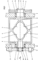
- the cylinder consists of a one-piece cast body with an outer body 1, which has webs 2 on the inside, each of which is arranged by the journal 3 arranged centrally to the lateral surface of the cylinder; 4 run in the axial direction to the center of the cylinder and have the shape of two hollow double cones which are brought together with their annular surfaces 6 in the center of the cylinder.
- the webs 2 have recesses 7 and core openings 8 in order to fix the mold core of the cylinder or to be able to remove the molding sand.
- the gripper devices for transferring the sheets to be printed are not shown.
- the axle pin 4 is designed as a drive pin and is seated in a bearing 11 arranged in the frame 9. Outside the frame 9, a gear wheel 12 is connected to the axle pin 4 in a rotationally fixed manner via a parallel key 10.
- a cover disk 13 is fastened centrally on the journal 4 by means of screws 14.
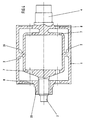
- the other axle pin 3 is designed as an adjustment pin, which is held in a bearing 16 which is fixed in a flange 17 and covered with a cover plate 18.
- the flange 17 has slots 19 through which adjustment cams 21 are guided, which are releasably connected to the frame 22.
- the axle journal 3 is arranged centrally in a tubular bearing journal 23.
- the bearing pin 23 is guided in a bearing 24 which is received by the frame 22.
- the gripper devices are not shown since they have no significance for the present invention.
- FIG. 1 view A of FIG. 1 is shown. From this it can be seen that the bearing 16 receiving the journal 3 can be clamped radially by means of the adjusting cams 21 via the flange 17.
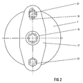
- FIG. 3 shows a longitudinal section through a further embodiment variant of a cylinder according to the invention with a rotationally symmetrical body, the bearings and the adjusting device having been omitted for the sake of simplicity, since these are designed as shown in FIGS. 1 and 2.
- the cylinder has a one-piece, rotationally symmetrical body, which is supported by both journal 3; 4 seen here, runs in the coaxial direction to the center of the cylinder in the form of two truncated cones, with their circular surfaces 6 merged and are firmly connected via webs 2 with the outer surface 1 of the cylinder.
- the two end faces of the cylinder have a number of core openings 8 in order to enable the casting of the cylinder or to be able to remove the molding sand.
- This variant of the cylinder is particularly advantageous wherever a simple design of the cast core is important and in the case of small cylinders in which the material accumulation of the axle beam is of no importance. It is also possible for the cylinder to be welded together from individual parts. These individual parts consist of the rotationally symmetrical body, a perforated disc as a web 2 and two further perforated discs which are arranged on the end face and welded to the inside of the outer surface 1. A tubular bearing journal 23, directed axially outwards, is welded on at least on one end face.
- FIG. 4 shows a longitudinal section through a third embodiment variant of a cylinder according to the invention with a rotationally symmetrical inner body, again the bearings and the adjusting device not being shown.
- the inner body in turn consists of a one-piece rotationally symmetrical cast body, which seen from both axle journals 3, 4, runs in the coaxial direction to the center of the cylinder in the form of two pots, which are brought together with the edges 26 and via webs 2 with the lateral surface 1 of the Cylinder are firmly connected.
- the two faces of the cylinder again have a number of core openings 8 in order to enable the casting of the cylinder or to be able to remove the molding sand.
- This variant of the cylinder is particularly advantageous for use in slim cylinders.
- axle journal 4 centrally on the drive side in a tubular journal 23 and to clamp it using an adjusting device.
Landscapes
- Engineering & Computer Science (AREA)
- Mechanical Engineering (AREA)
- General Engineering & Computer Science (AREA)
- Supply, Installation And Extraction Of Printed Sheets Or Plates (AREA)
- Feeding Of Articles By Means Other Than Belts Or Rollers (AREA)
- Rotary Presses (AREA)
- Paper (AREA)
- Folding Of Thin Sheet-Like Materials, Special Discharging Devices, And Others (AREA)
Claims (9)
- Cylindre de guidage du papier dans des machines rotatives à imprimer des feuilles, comprenant un corps extérieur qui est muni de tourillons d'axe (3 ; 4) et qui est formé d'une surface périphérique (1) pourvue d'évidements pour le système preneur ou de traverses prolongées par des entretoises ou des faces frontales, de façon à créer un corps creux, à l'intérieur du corps creux étant prévu un corps à symétrie de révolution qui fait fonction d'axe et peut être réglé de manière excentrique au moyen d'un dispositif de réglage, qui est relié au corps extérieur aussi bien sur un premier côté par l'intermédiaire d'un tourillon d'axe (4) qu'au centre par l'intermédiaire d'entretoises, qui sort à l'extérieur sur un second côté à travers un tourillon tubulaire d'appui (23) et qui est muni à cet endroit d'un palier (16) monté en position centrale, caractérisé en ce que le corps à symétrie de révolution est solidarisé au corps extérieur aussi bien au centre de son côté faisant face au tourillon tubulaire d'appui (23), en l'occurrence par l'intermédiaire d'entretoises (2) ou d'une surface circulaire ou annulaire (6), qu'en son centre, et en ce que le côté du corps à symétrie de révolution qui traverse le tourillon tubulaire d'appui (23) peut être réglé de manière excentrique au moyen du palier (16).
- Cylindre selon la revendication 1, caractérisé en ce que le corps à symétrie de révolution présente la forme de deux cônes creux qui sont solidarisés radialement par leurs bases annulaires (6) à la surface périphérique (1) du cylindre.
- Cylindre selon la revendication 1, caractérisé en ce que le corps à symétrie de révolution présente la forme de deux cônes qui sont solidarisés radialement par leurs bases circulaires (6), au moyen d'entretoises (2), à la surface périphérique (1) du cylindre.
- Cylindre selon la revendication 1, caractérisé en ce que le corps à symétrie de révolution présente la forme de deux pots qui sont solidarisés radialement par leurs bords (26), au moyen d'entretoises (2), à la surface périphérique (1) du cylindre.
- Cylindre selon les revendications 1 à 4, caractérisé en ce que le dispositif de réglage est constitué d'une bride (17) qui comporte en son centre un palier (16) pour recevoir le tourillon d'axe (3) et est pourvue de trous oblongs (19), et en ce que la bride (17) est montée sur le bâti avec une possibilité d'ajustement au moyen de cames de réglage (21).
- Cylindre selon les revendications 1 à 5, caractérisé en ce que les deux tourillons d'axe (3 ; 4) sont disposés chacun coaxialement dans les tourillons tubulaires d'appui (23) qui peuvent être ajustés au moyen de dispositifs de réglage.
- Cylindre selon les revendications 1 à 4, caractérisé en ce qu'il est prévu, dans le cylindre, des orifices noyautés (8) et, dans le corps à symétrie de révolution, des évidements (7).
- Cylindre selon la revendication 1 à 7, caractérisé en ce que le corps creux est réalisé et moulé d'une seule pièce avec le corps à symétrie de révolution disposé à l'intérieur.
- Cylindre selon les revendications 1 et 3, caractérisé en ce que le corps creux ou la surface périphérique (1) sont conçus de manière à pouvoir être soudés d'une seule pièce au corps à symétrie de révolution par l'intermédiaire des entretoises (2) et de faces frontales pourvues d'au moins un tourillon tubulaire d'appui (23).
Applications Claiming Priority (2)
| Application Number | Priority Date | Filing Date | Title |
|---|---|---|---|
| DE4119824 | 1991-06-15 | ||
| DE4119824A DE4119824C1 (fr) | 1991-06-15 | 1991-06-15 |
Publications (2)
| Publication Number | Publication Date |
|---|---|
| EP0523367A1 EP0523367A1 (fr) | 1993-01-20 |
| EP0523367B1 true EP0523367B1 (fr) | 1996-04-10 |
Family
ID=6434053
Family Applications (1)
| Application Number | Title | Priority Date | Filing Date |
|---|---|---|---|
| EP92109612A Expired - Lifetime EP0523367B1 (fr) | 1991-06-15 | 1992-06-06 | Cylindre de guidage du papier dans des machines rotatives à imprimer des feuilles |
Country Status (5)
| Country | Link |
|---|---|
| US (1) | US5235912A (fr) |
| EP (1) | EP0523367B1 (fr) |
| JP (1) | JPH0780297B2 (fr) |
| DE (3) | DE4119824C1 (fr) |
| RU (1) | RU2042526C1 (fr) |
Families Citing this family (15)
| Publication number | Priority date | Publication date | Assignee | Title |
|---|---|---|---|---|
| DE4335351C2 (de) * | 1993-10-16 | 2003-04-30 | Heidelberger Druckmasch Ag | Verfahren und Vorrichtung zur Kompensation von Passerabweichungen in einer Offsetrotationsdruckmaschine |
| DE4406572B4 (de) * | 1994-03-01 | 2004-06-03 | Heidelberger Druckmaschinen Ag | Rotationsdruckmaschine |
| DE4431114C2 (de) * | 1994-09-01 | 1999-11-18 | Roland Man Druckmasch | Bogenführender Trommelkörper für eine Druckmaschine |
| ES2140289B1 (es) * | 1996-04-02 | 2000-08-16 | Windmoeller & Hoelscher | Casquillo para cilindros impresores. |
| DE19613145C2 (de) * | 1996-04-02 | 2001-04-19 | Windmoeller & Hoelscher | Hülse für Walzen von Druckmaschinen |
| DE19647067A1 (de) * | 1996-11-14 | 1998-05-28 | Heidelberger Druckmasch Ag | Rotationsdruckmaschine |
| DE19647069A1 (de) * | 1996-11-14 | 1998-05-20 | Heidelberger Druckmasch Ag | Gußkörper |
| DE29701547U1 (de) | 1997-01-30 | 1997-03-20 | Voith Sulzer Papiermaschinen GmbH, 89522 Heidenheim | Walze für Auftragseinrichtung |
| AU2002220438A1 (en) * | 2001-12-19 | 2003-06-30 | Gallus Ferd. Ruesch Ag | Pressure cylinder in the form of a hollow cylinder made of metal |
| DE10250691B4 (de) * | 2002-10-31 | 2006-03-02 | Koenig & Bauer Ag | Rotationskörper einer Druckmaschine mit einem Grundkörper |
| DE10250689B3 (de) * | 2002-10-31 | 2004-12-09 | Koenig & Bauer Ag | Verfahren zur Herstellung eines Rotationskörpers sowie ein danach hergestellter Rotationskörper |
| DE10250683B3 (de) * | 2002-10-31 | 2004-03-18 | Koenig & Bauer Ag | Verfahren zur Herstellung eines Rotationskörpers einer Druckmaschine und einen danach hergestellten Rotationskörper |
| DE20221793U1 (de) | 2002-10-31 | 2007-10-31 | Koenig & Bauer Aktiengesellschaft | Rotationskörper einer Druckmaschine mit einem Ballen |
| DE10250690B4 (de) * | 2002-10-31 | 2006-03-02 | Koenig & Bauer Ag | Rotationskörper einer Druckmaschine mit einem Ballen |
| DE102013018582B4 (de) * | 2012-12-07 | 2021-11-25 | Heidelberger Druckmaschinen Intellectual Property Ag & Co. Kg | Drucktechnische Maschine und Lagerung für eine Welle einer drucktechnischen Maschine |
Family Cites Families (8)
| Publication number | Priority date | Publication date | Assignee | Title |
|---|---|---|---|---|
| US242058A (en) * | 1881-05-24 | sohtjrmann | ||
| BE356247A (fr) * | 1927-12-08 | |||
| US2048005A (en) * | 1934-12-20 | 1936-07-21 | Hoe & Co R | Cylinder for printing machines |
| US3161125A (en) * | 1961-02-15 | 1964-12-15 | Beloit Iron Works | Adjustable crown roll |
| DE3005690A1 (de) * | 1980-02-15 | 1981-08-20 | M.A.N.- Roland Druckmaschinen AG, 6050 Offenbach | Vorrichtung zum durchbiegen einer druckwalze einer rotationsdruckmaschine |
| FI67675C (fi) * | 1980-09-04 | 1985-05-10 | Frankenthal Ag Albert | Cylinder foer banformiga material bearbetande maskiner |
| US4487122A (en) * | 1983-11-04 | 1984-12-11 | Gravure Research Institute, Inc. | Deflection compensating roll for providing uniform contact pressure |
| DE3823846A1 (de) * | 1988-07-14 | 1990-01-18 | Heidelberger Druckmasch Ag | Zylinder im druckwerk von bogen-rotationsdruckmaschinen |
-
1991
- 1991-06-15 DE DE4119824A patent/DE4119824C1/de not_active Expired - Lifetime
- 1991-06-15 DE DE9116367U patent/DE9116367U1/de not_active Expired - Lifetime
-
1992
- 1992-06-06 DE DE59205937T patent/DE59205937D1/de not_active Expired - Fee Related
- 1992-06-06 EP EP92109612A patent/EP0523367B1/fr not_active Expired - Lifetime
- 1992-06-12 US US07/897,815 patent/US5235912A/en not_active Expired - Fee Related
- 1992-06-12 RU SU925052069A patent/RU2042526C1/ru active
- 1992-06-15 JP JP4155262A patent/JPH0780297B2/ja not_active Expired - Lifetime
Also Published As
| Publication number | Publication date |
|---|---|
| DE4119824C1 (fr) | 1992-12-03 |
| JPH0780297B2 (ja) | 1995-08-30 |
| DE9116367U1 (de) | 1992-09-24 |
| US5235912A (en) | 1993-08-17 |
| DE59205937D1 (de) | 1996-05-15 |
| JPH05169630A (ja) | 1993-07-09 |
| RU2042526C1 (ru) | 1995-08-27 |
| EP0523367A1 (fr) | 1993-01-20 |
Similar Documents
| Publication | Publication Date | Title |
|---|---|---|
| EP0523367B1 (fr) | Cylindre de guidage du papier dans des machines rotatives à imprimer des feuilles | |
| EP1449657B1 (fr) | Unité d'impression et presse rotative à imprimer | |
| DE3535621C2 (fr) | ||
| EP0894623B1 (fr) | Groupe imprimant pour une machine rotative | |
| DE3428668C2 (fr) | ||
| EP1541347A2 (fr) | Unité d'impression d'une machine d'impression | |
| DE3623405C2 (fr) | ||
| EP0194559B1 (fr) | Surface d'appui réglable en hauteur pour pinces de tambour de retournement dans les machines d'impression à retiration | |
| EP0172412A2 (fr) | Cylindre de transfert de feuilles dans les rotatives d'impression de feuilles | |
| DE3812137A1 (de) | Vorrichtung zum befestigen einer biegsamen druckplatte | |
| WO2001083215A1 (fr) | Dispositifs permettant de recouvrir un cylindre d'un habillage avec des elements de reperage | |
| DE10318477A1 (de) | Rollenrotationsdruckmaschine | |
| DE19533178C2 (de) | Zylinder | |
| DE3115141C2 (de) | Vorrichtung zum Diagonalverstellen eines Zylinders einer Druckmaschine, vorzugsweise des Plattenzylinders einer Bogenrotations-Offsetdruckmaschine | |
| DE19647067A1 (de) | Rotationsdruckmaschine | |
| EP1042123B1 (fr) | Rouleau | |
| DE20320707U1 (de) | Druckmaschine | |
| DE2926765A1 (de) | Vorrichtung zur unterdrueckung von biegeschwingungen in rotations-offsetdruckmaschinen | |
| DE3220530C2 (de) | Vorrichtung zum Aufspannen von Tiefdruckplatten | |
| DE20220293U1 (de) | Druckeinheit und eine Rotationsdruckmaschine | |
| DE2759773C2 (de) | Bogenübergabetrommel für von Schön- auf Schön- und Widerdruck umstellbare, Mehrfarben-Bogen-Rotations-Druckmaschinen | |
| EP1707361A2 (fr) | Rouleau applicateur pour un groupe d'impression offset | |
| DE19841912A1 (de) | Vorrichtung zum Befestigen von biegsamen Druckformen | |
| DE4435342C2 (de) | Vorrichtung zum Dämpfen der stoßartigen Druckspannung zwischen Gummituchzylinder und Druckzylinder von Rotationsdruckmaschinen | |
| DE20220296U1 (de) | Druckeinheit und eine Rotationsdruckmaschine |
Legal Events
| Date | Code | Title | Description |
|---|---|---|---|
| PUAI | Public reference made under article 153(3) epc to a published international application that has entered the european phase |
Free format text: ORIGINAL CODE: 0009012 |
|
| AK | Designated contracting states |
Kind code of ref document: A1 Designated state(s): CH DE FR GB IT LI SE |
|
| 17P | Request for examination filed |
Effective date: 19930209 |
|
| 17Q | First examination report despatched |
Effective date: 19941024 |
|
| RAP1 | Party data changed (applicant data changed or rights of an application transferred) |
Owner name: KOENIG & BAUER-ALBERT AKTIENGESELLSCHAFT |
|
| RAP1 | Party data changed (applicant data changed or rights of an application transferred) |
Owner name: KOENIG & BAUER-ALBERT AKTIENGESELLSCHAFT |
|
| ITF | It: translation for a ep patent filed | ||
| GRAH | Despatch of communication of intention to grant a patent |
Free format text: ORIGINAL CODE: EPIDOS IGRA |
|
| GRAA | (expected) grant |
Free format text: ORIGINAL CODE: 0009210 |
|
| AK | Designated contracting states |
Kind code of ref document: B1 Designated state(s): CH DE FR GB IT LI SE |
|
| ET | Fr: translation filed | ||
| GBT | Gb: translation of ep patent filed (gb section 77(6)(a)/1977) |
Effective date: 19960415 |
|
| REF | Corresponds to: |
Ref document number: 59205937 Country of ref document: DE Date of ref document: 19960515 |
|
| PLBE | No opposition filed within time limit |
Free format text: ORIGINAL CODE: 0009261 |
|
| STAA | Information on the status of an ep patent application or granted ep patent |
Free format text: STATUS: NO OPPOSITION FILED WITHIN TIME LIMIT |
|
| 26N | No opposition filed | ||
| PGFP | Annual fee paid to national office [announced via postgrant information from national office to epo] |
Ref country code: GB Payment date: 20000522 Year of fee payment: 9 |
|
| PGFP | Annual fee paid to national office [announced via postgrant information from national office to epo] |
Ref country code: FR Payment date: 20000615 Year of fee payment: 9 |
|
| PGFP | Annual fee paid to national office [announced via postgrant information from national office to epo] |
Ref country code: SE Payment date: 20000621 Year of fee payment: 9 |
|
| PGFP | Annual fee paid to national office [announced via postgrant information from national office to epo] |
Ref country code: DE Payment date: 20000704 Year of fee payment: 9 |
|
| PGFP | Annual fee paid to national office [announced via postgrant information from national office to epo] |
Ref country code: CH Payment date: 20000705 Year of fee payment: 9 |
|
| PG25 | Lapsed in a contracting state [announced via postgrant information from national office to epo] |
Ref country code: GB Free format text: LAPSE BECAUSE OF NON-PAYMENT OF DUE FEES Effective date: 20010606 |
|
| PG25 | Lapsed in a contracting state [announced via postgrant information from national office to epo] |
Ref country code: SE Free format text: LAPSE BECAUSE OF NON-PAYMENT OF DUE FEES Effective date: 20010607 |
|
| PG25 | Lapsed in a contracting state [announced via postgrant information from national office to epo] |
Ref country code: LI Free format text: LAPSE BECAUSE OF NON-PAYMENT OF DUE FEES Effective date: 20010630 Ref country code: CH Free format text: LAPSE BECAUSE OF NON-PAYMENT OF DUE FEES Effective date: 20010630 |
|
| GBPC | Gb: european patent ceased through non-payment of renewal fee |
Effective date: 20010606 |
|
| EUG | Se: european patent has lapsed |
Ref document number: 92109612.9 |
|
| REG | Reference to a national code |
Ref country code: CH Ref legal event code: PL |
|
| PG25 | Lapsed in a contracting state [announced via postgrant information from national office to epo] |
Ref country code: FR Free format text: LAPSE BECAUSE OF NON-PAYMENT OF DUE FEES Effective date: 20020228 |
|
| PG25 | Lapsed in a contracting state [announced via postgrant information from national office to epo] |
Ref country code: DE Free format text: LAPSE BECAUSE OF NON-PAYMENT OF DUE FEES Effective date: 20020403 |
|
| PG25 | Lapsed in a contracting state [announced via postgrant information from national office to epo] |
Ref country code: IT Free format text: LAPSE BECAUSE OF NON-PAYMENT OF DUE FEES Effective date: 20050606 |