EP0523367B1 - Cylinder for guiding paper in sheet-fed rotary printing machines - Google Patents
Cylinder for guiding paper in sheet-fed rotary printing machines Download PDFInfo
- Publication number
- EP0523367B1 EP0523367B1 EP92109612A EP92109612A EP0523367B1 EP 0523367 B1 EP0523367 B1 EP 0523367B1 EP 92109612 A EP92109612 A EP 92109612A EP 92109612 A EP92109612 A EP 92109612A EP 0523367 B1 EP0523367 B1 EP 0523367B1
- Authority
- EP
- European Patent Office
- Prior art keywords
- cylinder
- rotationally symmetrical
- cylinder according
- symmetrical body
- journal
- Prior art date
- Legal status (The legal status is an assumption and is not a legal conclusion. Google has not performed a legal analysis and makes no representation as to the accuracy of the status listed.)
- Expired - Lifetime
Links
Images

Classifications
-
- F—MECHANICAL ENGINEERING; LIGHTING; HEATING; WEAPONS; BLASTING
- F16—ENGINEERING ELEMENTS AND UNITS; GENERAL MEASURES FOR PRODUCING AND MAINTAINING EFFECTIVE FUNCTIONING OF MACHINES OR INSTALLATIONS; THERMAL INSULATION IN GENERAL
- F16C—SHAFTS; FLEXIBLE SHAFTS; ELEMENTS OR CRANKSHAFT MECHANISMS; ROTARY BODIES OTHER THAN GEARING ELEMENTS; BEARINGS
- F16C13/00—Rolls, drums, discs, or the like; Bearings or mountings therefor
- F16C13/02—Bearings
- F16C13/022—Bearings supporting a hollow roll mantle rotating with respect to a yoke or axle
- F16C13/024—Bearings supporting a hollow roll mantle rotating with respect to a yoke or axle adjustable for positioning, e.g. radial movable bearings for controlling the deflection along the length of the roll mantle
-
- B—PERFORMING OPERATIONS; TRANSPORTING
- B41—PRINTING; LINING MACHINES; TYPEWRITERS; STAMPS
- B41F—PRINTING MACHINES OR PRESSES
- B41F13/00—Common details of rotary presses or machines
- B41F13/08—Cylinders
-
- B—PERFORMING OPERATIONS; TRANSPORTING
- B41—PRINTING; LINING MACHINES; TYPEWRITERS; STAMPS
- B41F—PRINTING MACHINES OR PRESSES
- B41F21/00—Devices for conveying sheets through printing apparatus or machines
- B41F21/10—Combinations of transfer drums and grippers
Definitions
- the invention relates to a cylinder for the paper guide on sheet-fed rotary printing presses according to the preamble of claim 1.
- a sheet to be transported depending on the configuration of the printing units, e.g. B. passed horizontally on one side by the gripper take-overs and after about half a turn to the grippers of the next cylinder, and the cylinder is down, for example, by gravity by 5 microns when taking over the bow bent, so after half a turn the gripper device points in the opposite direction. Deflections are caused not only by gravity, but also by drive components on the gear train and by forces in the pressure zone.
- a cylinder in the printing unit of sheet-fed rotary printing presses is known, in which the bending of the cylinder is counteracted in that the cylinders are designed as hollow bodies and that an axis is mounted in at least three places in the hollow body and that Axis on the middle bearing is eccentric to brace the axis and cylinder.
- the invention has for its object to provide a cylinder for the paper guide on sheet-fed rotary printing machines with gripping devices for transferring the sheets to be printed, which is equipped in a simple manner so that the deflection of the cylinder is counteracted.
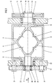
- the cylinder consists of a one-piece cast body with an outer body 1, which has webs 2 on the inside, each of which is arranged by the journal 3 arranged centrally to the lateral surface of the cylinder; 4 run in the axial direction to the center of the cylinder and have the shape of two hollow double cones which are brought together with their annular surfaces 6 in the center of the cylinder.
- the webs 2 have recesses 7 and core openings 8 in order to fix the mold core of the cylinder or to be able to remove the molding sand.
- the gripper devices for transferring the sheets to be printed are not shown.
- the axle pin 4 is designed as a drive pin and is seated in a bearing 11 arranged in the frame 9. Outside the frame 9, a gear wheel 12 is connected to the axle pin 4 in a rotationally fixed manner via a parallel key 10.
- a cover disk 13 is fastened centrally on the journal 4 by means of screws 14.
- the other axle pin 3 is designed as an adjustment pin, which is held in a bearing 16 which is fixed in a flange 17 and covered with a cover plate 18.
- the flange 17 has slots 19 through which adjustment cams 21 are guided, which are releasably connected to the frame 22.
- the axle journal 3 is arranged centrally in a tubular bearing journal 23.
- the bearing pin 23 is guided in a bearing 24 which is received by the frame 22.
- the gripper devices are not shown since they have no significance for the present invention.
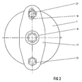
- FIG. 1 view A of FIG. 1 is shown. From this it can be seen that the bearing 16 receiving the journal 3 can be clamped radially by means of the adjusting cams 21 via the flange 17.
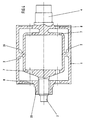
- FIG. 3 shows a longitudinal section through a further embodiment variant of a cylinder according to the invention with a rotationally symmetrical body, the bearings and the adjusting device having been omitted for the sake of simplicity, since these are designed as shown in FIGS. 1 and 2.
- the cylinder has a one-piece, rotationally symmetrical body, which is supported by both journal 3; 4 seen here, runs in the coaxial direction to the center of the cylinder in the form of two truncated cones, with their circular surfaces 6 merged and are firmly connected via webs 2 with the outer surface 1 of the cylinder.
- the two end faces of the cylinder have a number of core openings 8 in order to enable the casting of the cylinder or to be able to remove the molding sand.
- This variant of the cylinder is particularly advantageous wherever a simple design of the cast core is important and in the case of small cylinders in which the material accumulation of the axle beam is of no importance. It is also possible for the cylinder to be welded together from individual parts. These individual parts consist of the rotationally symmetrical body, a perforated disc as a web 2 and two further perforated discs which are arranged on the end face and welded to the inside of the outer surface 1. A tubular bearing journal 23, directed axially outwards, is welded on at least on one end face.
- FIG. 4 shows a longitudinal section through a third embodiment variant of a cylinder according to the invention with a rotationally symmetrical inner body, again the bearings and the adjusting device not being shown.
- the inner body in turn consists of a one-piece rotationally symmetrical cast body, which seen from both axle journals 3, 4, runs in the coaxial direction to the center of the cylinder in the form of two pots, which are brought together with the edges 26 and via webs 2 with the lateral surface 1 of the Cylinder are firmly connected.
- the two faces of the cylinder again have a number of core openings 8 in order to enable the casting of the cylinder or to be able to remove the molding sand.
- This variant of the cylinder is particularly advantageous for use in slim cylinders.
- axle journal 4 centrally on the drive side in a tubular journal 23 and to clamp it using an adjusting device.
Description
Die Erfindung betrifft einen Zylinder für die Papierführung an Bogenrotationsdruckmaschinen gemäß dem Oberbegriff des Patentanspruches 1.The invention relates to a cylinder for the paper guide on sheet-fed rotary printing presses according to the preamble of
Es ist bekannt, daß bei papierführenden Zylindern von Bogenrotationsdruckmaschinen Passerfehler auftreten können. Ursache dieser Passerfehler sind einesteils Deformationen des Papiers durch Druck und Feuchtung. Anderenteils werden aber Deformationen der Bogenvorderkante durch Verbiegungen der papierführenden Zylinder, im Bereich von 5 bis 10 µm verursacht. Das Maß der Durchbiegung eines Zylinders tritt verdoppelt als Passerfehler in Erscheinung. Die Vielzahl der Übergabestellen an Mehrfarbenmaschinen, ca. 6 bis 12, können konkave Deformationen der Bogenvorderkantenlinie im Bereich von 0,1 µm verursachen. Dazu muß noch folgendes bemerkt werden.It is known that registration errors can occur in paper-guiding cylinders of sheet-fed rotary printing presses. The cause of these registration errors is partly deformation of the paper due to pressure and dampening. On the other hand, deformations of the leading edge of the sheet are caused by bending of the paper-guiding cylinders in the range of 5 to 10 µm. The degree of deflection of a cylinder appears twice as a registration error. The multitude of transfer points on multi-color machines, approx. 6 to 12, can cause concave deformations of the sheet front edge line in the range of 0.1 µm. The following must also be noted.
Wird ein zu transportierender Bogen, je nach Konfiguration der Druckwerke, z. B. in der Horizontalen auf der einen Seite durch die Greiferübernahmen und nach ca. einer halben Umdrehung an die Greifer des nächstfolgenden Zylinders übergeben, und ist der Zylinder beispielsweise durch die Schwerkraft um 5 µm bei der Bogenübernahme nach unten gebogen, so zeigt nach einer halben Umdrehung die Greifereinrichtung in die entgegengesetzte Richtung. Durchbiegungen werden nicht nur durch Schwerkräfte, sondern auch durch Antriebskomponenten am Räderzug und durch Kräfte in der Druckzone bewirkt.If a sheet to be transported, depending on the configuration of the printing units, e.g. B. passed horizontally on one side by the gripper take-overs and after about half a turn to the grippers of the next cylinder, and the cylinder is down, for example, by gravity by 5 microns when taking over the bow bent, so after half a turn the gripper device points in the opposite direction. Deflections are caused not only by gravity, but also by drive components on the gear train and by forces in the pressure zone.
Gemäß DE-OS 38 23 846 ist ein Zylinder im Druckwerk von Bogen-Rotationsdruckmaschinen bekannt, bei welchem der Verbiegung des Zylinders dadurch entgegengewirkt wird, daß die Zylinder als Hohlkörper ausgebildet sind und daß im Hohlkörper eine Achse an mindestens drei Stellen gelagert ist und daß die Achse am mittleren Lager exzentrisch ausgebildet ist, um Achse und Zylinder zu verspannen.According to DE-OS 38 23 846 a cylinder in the printing unit of sheet-fed rotary printing presses is known, in which the bending of the cylinder is counteracted in that the cylinders are designed as hollow bodies and that an axis is mounted in at least three places in the hollow body and that Axis on the middle bearing is eccentric to brace the axis and cylinder.
Nachteilig bei diesem Zylinder ist, daß drei zusätzliche Lagerstellen notwendig sind, daß der Hohlkörper mit drei präzis fluchtenden Bohrungen zur Aufnahme der drei Lager versehen sein muß.The disadvantage of this cylinder is that three additional bearing points are necessary that the hollow body must be provided with three precisely aligned holes for receiving the three bearings.
Der Erfindung liegt die Aufgabe zugrunde, einen Zylinder für die Papierführung an Bogenrotationsdruckmaschinen mit Greifeinrichtungen zum Überführen der zu bedruckenden Bogen zu schaffen, der auf einfache Art so ausgestattet ist, daß der Durchbiegung des Zylinder entgegenwirkt wird.The invention has for its object to provide a cylinder for the paper guide on sheet-fed rotary printing machines with gripping devices for transferring the sheets to be printed, which is equipped in a simple manner so that the deflection of the cylinder is counteracted.
Erfindungsgemäß wird die Aufgabe durch den kennzeichnenden Teil des Anspruchs 1 gelöst. Zweckmäßige Ausgestaltungen der Erfindung sind den Unteransprüchen zu entnehmen.According to the invention the object is solved by the characterizing part of
Die Durchbiegungen von bogenführenden Zylindern in den verschiedenen Größenordnungen, die durch Eigengewicht, durch Druckspannung und durch die Antriebskräfte entstehen können, sind durch den erfindungsgemäßen Aufbau des Zylinders weitestgehend vermieden. Sollten dennoch geringfügige Durchbiegungserscheinungen auftreten, so können diese mit der Justiereinrichtung über den zentrisch im rohrförmigen Lagerzapfen angeordneten Achszapfen ausgeglichen werden. Somit kann auch eine mögliche Korrektur der Bogenvorderkanten in konkaver oder konvexer Richtung vorgenommen werden, nachträglich oder bei laufender Maschine.The deflections of sheet-guiding cylinders in the various orders of magnitude, which can arise from their own weight, from compressive stress and from the driving forces, are largely avoided by the construction of the cylinder according to the invention. Should slight deflection phenomena nevertheless occur, these can be compensated for with the adjustment device via the axle journal arranged centrally in the tubular bearing journal. This means that a possible correction of the leading edge of the sheet in concave or convex direction can also be carried out subsequently or with the machine running.
Durch die Anordnung von zwei rohrförmigen Lagerzapfen ist es auch möglich, die beiden darin zentrisch gelagerten Achszapfen durch beidseitig vorhandene Justiereinrichtungen zu verspannen, was bei langen schlanken Walzen von Vorteil sein kann.Due to the arrangement of two tubular bearing journals, it is also possible to brace the two axle journals, which are mounted centrally therein, by adjusting devices provided on both sides, which can be advantageous in the case of long, slim rollers.
Die Erfindung soll nachstehend an mehreren Ausführungsbeispielen näher erläutert werden. Die zugehörigen Zeichnungen zeigen:
- Fig. 1
- einen Längsschnitt durch einen erfindungsgemäßen Zylinder mit Lagerzapfen, Lagern und Verstelleinrichtung;
- Fig. 2
- die Ansicht A nach Fig. 1;
- Fig. 3
- einen Längsschnitt durch eine zweite Ausführungsvariante eines erfindungsgemäßen Zylinders, jedoch ohne Lager und Verstelleinrichtung;
- Fig. 4
- einen Längsschnitt durch eine dritte Ausführungsvariante eines erfindungsgemäßen Zylinders.
- Fig. 1
- a longitudinal section through a cylinder according to the invention with journals, bearings and adjusting device;
- Fig. 2
- the view A of FIG. 1;
- Fig. 3
- a longitudinal section through a second embodiment of a cylinder according to the invention, but without a bearing and adjusting device;
- Fig. 4
- a longitudinal section through a third embodiment of a cylinder according to the invention.
Der Zylinder besteht gemäß Fig. 1 aus einem einteiligen Gußkörper mit Außenkörper 1, welcher im Inneren Stege 2 aufweist, die jeweils von den zentrisch zur Mantelfläche des Zylinders angeordneten Achszapfen 3; 4 in axialer Richtung zur Mitte des Zylinders verlaufen und die Form von zwei hohlen Doppelkegeln besitzen, welche in der Zylindermitte mit ihren ringförmigen Flächen 6 zusammengeführt sind. Die Stege 2 weisen Ausnehmungen 7 und Kernöffnungen 8 auf, um den Formkern des Zylinders zu fixieren bzw. um den Formsand entfernen zu können. Die Greifereinrichtungen zum Überführen der zu bedruckenden Bogen sind nicht dargestellt. Der Achszapfen 4 ist als Antriebszapfen ausgebildet und sitzt in einem im Gestell 9 angeordneten Lager 11. Außerhalb des Gestells 9 ist ein Zahnrad 12 über eine Paßfeder 10 drehfest mit dem Achszapfen 4 verbunden. Zentrisch auf dem Achszapfen 4 ist eine Abdeckscheibe 13 mittels Schrauben 14 befestigt.According to FIG. 1, the cylinder consists of a one-piece cast body with an
Der andere Achszapfen 3 ist als Verstellzapfen ausgeführt, welcher in einem Lager 16 gehalten ist, das in einem Flansch 17 befestigt und mit einer Abdeckscheibe 18 abgedeckt ist. Der Flansch 17 besitzt Langlöcher 19, durch welche Verstellnocken 21 geführt sind, die mit dem Gestell 22 lösbar verbunden sind. Der Achszapfen 3 ist in einem rohrförmigen Lagerzapfen 23 zentrisch angeordnet. Der Lagerzapfen 23 ist in einem Lager 24 geführt, welches vom Gestell 22 aufgenommen wird. Die Greifereinrichtungen sind nicht dargestellt, da diese für die vorliegende Erfindung keine Bedeutung haben.The
Gemäß Fig. 2 ist die Ansicht A nach Fig. 1 dargestellt. Hieraus ist ersichtlich, daß das den Achszapfen 3 aufnehmende Lager 16 mittels der Verstellnocken 21 über den Flansch 17 radial verspannbar ist.2, view A of FIG. 1 is shown. From this it can be seen that the bearing 16 receiving the
Statt des Flansches 17 und der Verstellnocken 21 können auch andere bekannte Justiereinrichtungen eingesetzt werden.Instead of the
Nach Fig. 3 ist ein Längsschnitt durch eine weitere Ausführungsvariante eines erfindungsgemäßen Zylinders mit einem rotationssymmetrischen Körper dargestellt, wobei der Einfachheit halber die Lager sowie die Verstelleinrichtung weggelassen wurden, da diese, wie in Fig. 1 und 2 dargestellt, ausgeführt sind. Der Zylinder besitzt einen einteiligen rotationssymmetrischen Körper, der von beiden Achszapfen 3; 4 her gesehen, in koaxialer Richtung zur Mitte des Zylinders jeweils in Form von zwei Kegelstümpfen verläuft, die mit ihren kreisförmigen Flächen 6 zusammengeführt und über Stege 2 mit der Mantelfläche 1 des Zylinders fest verbunden sind. Die beiden Stirnseiten des Zylinders weisen eine Anzahl von Kernöffnungen 8 auf, um das Gießen des Zylinders zu ermöglichen bzw. um den Formsand entfernen zu können.3 shows a longitudinal section through a further embodiment variant of a cylinder according to the invention with a rotationally symmetrical body, the bearings and the adjusting device having been omitted for the sake of simplicity, since these are designed as shown in FIGS. 1 and 2. The cylinder has a one-piece, rotationally symmetrical body, which is supported by both
Diese Ausführungsvariante des Zylinders ist besonders vorteilhaft dort einzusetzen, wo auf eine einfache Gestaltung des Gußkerns Wert gelegt wird und bei kleinen Zylindern, bei denen die Materialanhäufung des Achskörpers ohne Bedeutung ist. Es ist auch möglich, daß der Zylinder aus Einzelteilen zusammengeschweißt wird. Dieses Einzelteile bestehen aus dem rotationssymmetrischen Körper, einer Lochscheibe als Steg 2 sowie zwei weiteren Lochscheiben, die stirnseitig angeordnet und mit dem Inneren der Mantelfläche 1 verschweißt sind. Zumindest an einer Stirnseite ist ein rohrförmiger Lagerzapfen 23, axial nach außen gerichtet, angeschweißt.This variant of the cylinder is particularly advantageous wherever a simple design of the cast core is important and in the case of small cylinders in which the material accumulation of the axle beam is of no importance. It is also possible for the cylinder to be welded together from individual parts. These individual parts consist of the rotationally symmetrical body, a perforated disc as a
Gemäß Fig. 4 ist ein Längsschnitt durch eine dritte Ausführungsvariante eines erfindungsgemäßen Zylinders mit einem rotationssymmetrischen Innenkörper dargestellt, wobei wiederum die Lager sowie die Verstelleinrichtung nicht gezeigt sind. Der Innenkörper besteht wiederum aus einem einteiligen rotationssymmetrischen Gußkörper, der von beiden Achszapfen 3, 4 her gesehen, in koaxialer Richtung zur Mitte des Zylinders jeweils in Form von zwei Töpfen verläuft, die mit den Rändern 26 zusammengeführt und über Stege 2 mit der Mantelfläche 1 des Zylinders fest verbunden sind. Die beiden Stirnseiten des Zylinders weisen wiederum eine Anzahl von Kernöffnungen 8 auf, um das Gießen des Zylinders zu ermöglichen bzw. um den Formsand entfernen zu können.4 shows a longitudinal section through a third embodiment variant of a cylinder according to the invention with a rotationally symmetrical inner body, again the bearings and the adjusting device not being shown. The inner body in turn consists of a one-piece rotationally symmetrical cast body, which seen from both
Diese Ausführungsvariante des Zylinders ist besonders vorteilhaft bei schlanken Zylindern einzusetzen.This variant of the cylinder is particularly advantageous for use in slim cylinders.
Weiterhin ist es möglich, bei der Verwendung von besonders langen oder schlanken Zylindern , auch den Achszapfen 4 auf der Antriebsseite ebenfalls in einem rohrförmigen Lagerzapfen 23 zentrisch anzuordnen und über eine Justiereinrichtung zu verspannen.Furthermore, when using particularly long or slim cylinders, it is also possible to arrange the
- 11
- Außenkörper, ZylindermantelOuter body, cylinder jacket
- 22nd
- Stegweb
- 33rd
- AchszapfenAxle journal
- 44th
- AchszapfenAxle journal
- 55
- --
- 66
- Flächesurface
- 77
- AusnehmungRecess
- 88th
- KernöffnungCore opening
- 99
- Gestellframe
- 1010th
- Paßfederadjusting spring
- 1111
- Lagercamp
- 1212th
- Zahnradgear
- 1313
- AbdeckscheibeCover plate
- 1414
- Schraubescrew
- 1515
- --
- 1616
- Lagercamp
- 1717th
- Flanschflange
- 1818th
- AbdeckscheibeCover plate
- 1919th
- LanglochLong hole
- 2020th
- --
- 2121
- VerstellnockenAdjustment cams
- 2222
- Gestellframe
- 2323
- Lagerzapfen, rohrförmigBearing journal, tubular
- 2424th
- Lagercamp
- 2525th
- --
- 2626
- Randedge
Claims (9)
- Cylinder for guiding paper in sheet-fed rotary printing machines, comprising an outer body which is provided with axle journals (3; 4) and is formed from a lateral surface (1) having openings for the gripper device or from crosspieces having adjoining webs or end faces, so that a hollow body exists, there being provided in an interior of the hollow body a rotationally symmetrical body as an axle, which can be adjusted eccentrically by means of an adjusting device, is connected both at a first side to an axle journal (4) and centrally via webs to the outer body, and at a second side projects outwardly through a tubular bearing journal (23) and is provided there with a centrically arranged bearing (16), characterised in that the rotationally symmetrical body is fixedly connected to the outer body both at its side located opposite the tubular bearing journal (23), centrally via webs (2) or a circular or annular surface (6), and at its centre, and in that the side of the rotationally symmetrical body which projects through the tubular bearing journal (23) is arranged such that it can be adjusted eccentrically by means of the bearing (16).
- Cylinder according to Claim 1, characterised in that the rotationally symmetrical body has the shape of two hollow cones which are fixedly connected radially to the lateral surface (1) of the cylinder at their annular bases (6).
- Cylinder according to Claim 1, characterised in that the rotationally symmetrical body has the shape of two cones which are fixedly connected radially to the lateral surface (1) of the cylinder by their circular bases (6) via webs (2).
- Cylinder according to Claim 1, characterised in that the rotationally symmetrical body has the shape of two pots which are fixedly connected radially to the lateral surface (1) of the cylinder by their rims (26) via webs (2).
- Cylinder according to Claim 1 to 4, characterised in that the adjusting device comprises a flange (17) which, centrally, has a bearing (16) for receiving the axle journal (3) and contains elongated holes (19), in that the flange (17) is arranged on the frame such that it can be adjusted by means of adjusting cams (21).
- Cylinder according to Claim 1 to 5, characterised in that both axle journals (3; 4) are in each case arranged coaxially in the tubular bearing journals (23), which can be adjusted via adjusting devices.
- Cylinder according to Claim 1 to 4, characterised in that core orifices (8) are provided in the cylinder and openings (7) are provided in the rotationally symmetrical body.
- Cylinder according to Claim 1 to 7, characterised in that the hollow body is constructed and cast in one piece with the rotationally symmetrical body arranged therein.
- Cylinder according to Claim 1 and 3, characterised in that the hollow body or the lateral surface (1) is designed such that it can be welded to form one piece with the rotationally symmetrical body via the webs (2) and end faces having at least one tubular bearing journal (23).
Applications Claiming Priority (2)
| Application Number | Priority Date | Filing Date | Title |
|---|---|---|---|
| DE4119824A DE4119824C1 (en) | 1991-06-15 | 1991-06-15 | |
| DE4119824 | 1991-06-15 |
Publications (2)
| Publication Number | Publication Date |
|---|---|
| EP0523367A1 EP0523367A1 (en) | 1993-01-20 |
| EP0523367B1 true EP0523367B1 (en) | 1996-04-10 |
Family
ID=6434053
Family Applications (1)
| Application Number | Title | Priority Date | Filing Date |
|---|---|---|---|
| EP92109612A Expired - Lifetime EP0523367B1 (en) | 1991-06-15 | 1992-06-06 | Cylinder for guiding paper in sheet-fed rotary printing machines |
Country Status (5)
| Country | Link |
|---|---|
| US (1) | US5235912A (en) |
| EP (1) | EP0523367B1 (en) |
| JP (1) | JPH0780297B2 (en) |
| DE (3) | DE4119824C1 (en) |
| RU (1) | RU2042526C1 (en) |
Families Citing this family (15)
| Publication number | Priority date | Publication date | Assignee | Title |
|---|---|---|---|---|
| DE4335351C2 (en) * | 1993-10-16 | 2003-04-30 | Heidelberger Druckmasch Ag | Method and device for compensating register deviations in an offset rotary printing machine |
| DE4406572B4 (en) * | 1994-03-01 | 2004-06-03 | Heidelberger Druckmaschinen Ag | Rotary press |
| DE4431114C2 (en) * | 1994-09-01 | 1999-11-18 | Roland Man Druckmasch | Sheet-guiding drum body for a printing machine |
| ES2140289B1 (en) * | 1996-04-02 | 2000-08-16 | Windmoeller & Hoelscher | BUSHING FOR PRINTER CYLINDERS. |
| DE29623591U1 (en) * | 1996-04-02 | 1999-01-07 | Windmoeller & Hoelscher | Sleeve for printing rollers |
| DE19647069A1 (en) * | 1996-11-14 | 1998-05-20 | Heidelberger Druckmasch Ag | Hollow cast body e.g. printing machine cylinder preform |
| DE19647067A1 (en) * | 1996-11-14 | 1998-05-28 | Heidelberger Druckmasch Ag | Rotary printing machine |
| DE29701547U1 (en) | 1997-01-30 | 1997-03-20 | Voith Sulzer Papiermasch Gmbh | Roller for application device |
| EP1456032B1 (en) | 2001-12-19 | 2008-04-30 | Gallus Ferd. Rüesch Ag | Pressure cylinder in the form of a hollow cylinder made of metal |
| DE10250683B3 (en) * | 2002-10-31 | 2004-03-18 | Koenig & Bauer Ag | Manufacturing rotation body for printing machine involves fitting outer body with flow channel incision for heat-carrying medium to base body, fitting cover that covers flow channel to outer body |
| DE10250689B3 (en) * | 2002-10-31 | 2004-12-09 | Koenig & Bauer Ag | Production of a rotational body for a printing machine comprises forming a web made from a material which liquefies on heating on an inner side of an outer body or on the surface of the base body |
| DE10250686A1 (en) * | 2002-10-31 | 2004-05-19 | Koenig & Bauer Ag | Process for tempering a bale of a rotating body of a printing machine and rotating body of a printing machine with a bale |
| DE10250690B4 (en) | 2002-10-31 | 2006-03-02 | Koenig & Bauer Ag | Rotational body of a printing machine with a bale |
| DE10250691B4 (en) * | 2002-10-31 | 2006-03-02 | Koenig & Bauer Ag | Rotational body of a printing press with a base body |
| DE102013018582B4 (en) * | 2012-12-07 | 2021-11-25 | Heidelberger Druckmaschinen Intellectual Property Ag & Co. Kg | Printing machine and bearing for a shaft of a printing machine |
Family Cites Families (8)
| Publication number | Priority date | Publication date | Assignee | Title |
|---|---|---|---|---|
| US242058A (en) * | 1881-05-24 | sohtjrmann | ||
| BE356247A (en) * | 1927-12-08 | |||
| US2048005A (en) * | 1934-12-20 | 1936-07-21 | Hoe & Co R | Cylinder for printing machines |
| US3161125A (en) * | 1961-02-15 | 1964-12-15 | Beloit Iron Works | Adjustable crown roll |
| DE3005690A1 (en) * | 1980-02-15 | 1981-08-20 | M.A.N.- Roland Druckmaschinen AG, 6050 Offenbach | Bending roller for rotary printing machine - has lever at each end deflected by power cylinder to apply bending moment to ram |
| FI67675C (en) * | 1980-09-04 | 1985-05-10 | Frankenthal Ag Albert | CYLINDER FOR BANFORM MATERIAL BEARBETANDE MASKINER |
| US4487122A (en) * | 1983-11-04 | 1984-12-11 | Gravure Research Institute, Inc. | Deflection compensating roll for providing uniform contact pressure |
| DE3823846A1 (en) * | 1988-07-14 | 1990-01-18 | Heidelberger Druckmasch Ag | CYLINDERS IN THE PRINTING PLANT OF BOW ROTATION PRINTING MACHINES |
-
1991
- 1991-06-15 DE DE4119824A patent/DE4119824C1/de not_active Expired - Lifetime
- 1991-06-15 DE DE9116367U patent/DE9116367U1/de not_active Expired - Lifetime
-
1992
- 1992-06-06 EP EP92109612A patent/EP0523367B1/en not_active Expired - Lifetime
- 1992-06-06 DE DE59205937T patent/DE59205937D1/en not_active Expired - Fee Related
- 1992-06-12 US US07/897,815 patent/US5235912A/en not_active Expired - Fee Related
- 1992-06-12 RU SU925052069A patent/RU2042526C1/en active
- 1992-06-15 JP JP4155262A patent/JPH0780297B2/en not_active Expired - Lifetime
Also Published As
| Publication number | Publication date |
|---|---|
| RU2042526C1 (en) | 1995-08-27 |
| DE4119824C1 (en) | 1992-12-03 |
| US5235912A (en) | 1993-08-17 |
| EP0523367A1 (en) | 1993-01-20 |
| DE9116367U1 (en) | 1992-09-24 |
| JPH05169630A (en) | 1993-07-09 |
| JPH0780297B2 (en) | 1995-08-30 |
| DE59205937D1 (en) | 1996-05-15 |
Similar Documents
| Publication | Publication Date | Title |
|---|---|---|
| EP0523367B1 (en) | Cylinder for guiding paper in sheet-fed rotary printing machines | |
| EP1449657B1 (en) | Printing unit and a rotary roller printing press | |
| DE3535621C2 (en) | ||
| EP0894623B1 (en) | Printing unit for a rotary press | |
| DE3428668C2 (en) | ||
| EP1541347A2 (en) | Printing unit of a printing machine | |
| DE3623405C2 (en) | ||
| EP1515848B2 (en) | Cylinder pair and cylinder of a printing unit of a rotary offset printing machine | |
| EP0194559B1 (en) | Gripper supports, adjustable in height, for the turning cylinder of perfecting printing machines | |
| EP0172412A2 (en) | Sheet transfer cylinder in sheet-fed rotary presses | |
| EP1688251B1 (en) | Printing unit of a printing machine | |
| DE3812137A1 (en) | DEVICE FOR FASTENING A FLEXIBLE PRINT PLATE | |
| WO2001083215A1 (en) | Device for providing a cylinder with a packing and registers | |
| EP1707361B1 (en) | Applicator roller for an offset printing group | |
| DE10318477A1 (en) | Rotary printing press for newspaper printing, has printing unit for printing six axially adjacent pages and folding device with transport cylinder receiving seven cut product lengths | |
| DE19533178C2 (en) | cylinder | |
| DE3115141C2 (en) | Device for diagonally adjusting a cylinder of a printing machine, preferably the plate cylinder of a sheet-fed rotary offset printing machine | |
| DE19647067A1 (en) | Rotary printing machine | |
| EP1042123B1 (en) | Roller | |
| DE20320707U1 (en) | press | |
| DE2926765A1 (en) | DEVICE FOR SUPPRESSING BENDING VIBRATIONS IN ROTATIONAL OFFSET PRINTING MACHINES | |
| DE10321989A1 (en) | Printing press for offset printing has at least one extra printing unit on plane above printing location of upper satellite printing unit | |
| DE3220530C2 (en) | Device for clamping intaglio printing plates | |
| DE2759773C2 (en) | Sheet transfer drum for multi-color sheet-fed rotary printing machines that can be converted from perfect to perfect | |
| DE19841912A1 (en) | Mounting for flexible printing plates at the plate cylinder of a rotary printing press has recesses at the flanks of the cylinder channel with leaf springs to push the bent plate ends into them |
Legal Events
| Date | Code | Title | Description |
|---|---|---|---|
| PUAI | Public reference made under article 153(3) epc to a published international application that has entered the european phase |
Free format text: ORIGINAL CODE: 0009012 |
|
| AK | Designated contracting states |
Kind code of ref document: A1 Designated state(s): CH DE FR GB IT LI SE |
|
| 17P | Request for examination filed |
Effective date: 19930209 |
|
| 17Q | First examination report despatched |
Effective date: 19941024 |
|
| RAP1 | Party data changed (applicant data changed or rights of an application transferred) |
Owner name: KOENIG & BAUER-ALBERT AKTIENGESELLSCHAFT |
|
| RAP1 | Party data changed (applicant data changed or rights of an application transferred) |
Owner name: KOENIG & BAUER-ALBERT AKTIENGESELLSCHAFT |
|
| ITF | It: translation for a ep patent filed |
Owner name: DE DOMINICIS & MAYER S.R.L. |
|
| GRAH | Despatch of communication of intention to grant a patent |
Free format text: ORIGINAL CODE: EPIDOS IGRA |
|
| GRAA | (expected) grant |
Free format text: ORIGINAL CODE: 0009210 |
|
| AK | Designated contracting states |
Kind code of ref document: B1 Designated state(s): CH DE FR GB IT LI SE |
|
| ET | Fr: translation filed | ||
| GBT | Gb: translation of ep patent filed (gb section 77(6)(a)/1977) |
Effective date: 19960415 |
|
| REF | Corresponds to: |
Ref document number: 59205937 Country of ref document: DE Date of ref document: 19960515 |
|
| PLBE | No opposition filed within time limit |
Free format text: ORIGINAL CODE: 0009261 |
|
| STAA | Information on the status of an ep patent application or granted ep patent |
Free format text: STATUS: NO OPPOSITION FILED WITHIN TIME LIMIT |
|
| 26N | No opposition filed | ||
| PGFP | Annual fee paid to national office [announced via postgrant information from national office to epo] |
Ref country code: GB Payment date: 20000522 Year of fee payment: 9 |
|
| PGFP | Annual fee paid to national office [announced via postgrant information from national office to epo] |
Ref country code: FR Payment date: 20000615 Year of fee payment: 9 |
|
| PGFP | Annual fee paid to national office [announced via postgrant information from national office to epo] |
Ref country code: SE Payment date: 20000621 Year of fee payment: 9 |
|
| PGFP | Annual fee paid to national office [announced via postgrant information from national office to epo] |
Ref country code: DE Payment date: 20000704 Year of fee payment: 9 |
|
| PGFP | Annual fee paid to national office [announced via postgrant information from national office to epo] |
Ref country code: CH Payment date: 20000705 Year of fee payment: 9 |
|
| PG25 | Lapsed in a contracting state [announced via postgrant information from national office to epo] |
Ref country code: GB Free format text: LAPSE BECAUSE OF NON-PAYMENT OF DUE FEES Effective date: 20010606 |
|
| PG25 | Lapsed in a contracting state [announced via postgrant information from national office to epo] |
Ref country code: SE Free format text: LAPSE BECAUSE OF NON-PAYMENT OF DUE FEES Effective date: 20010607 |
|
| PG25 | Lapsed in a contracting state [announced via postgrant information from national office to epo] |
Ref country code: LI Free format text: LAPSE BECAUSE OF NON-PAYMENT OF DUE FEES Effective date: 20010630 Ref country code: CH Free format text: LAPSE BECAUSE OF NON-PAYMENT OF DUE FEES Effective date: 20010630 |
|
| GBPC | Gb: european patent ceased through non-payment of renewal fee |
Effective date: 20010606 |
|
| EUG | Se: european patent has lapsed |
Ref document number: 92109612.9 |
|
| REG | Reference to a national code |
Ref country code: CH Ref legal event code: PL |
|
| PG25 | Lapsed in a contracting state [announced via postgrant information from national office to epo] |
Ref country code: FR Free format text: LAPSE BECAUSE OF NON-PAYMENT OF DUE FEES Effective date: 20020228 |
|
| PG25 | Lapsed in a contracting state [announced via postgrant information from national office to epo] |
Ref country code: DE Free format text: LAPSE BECAUSE OF NON-PAYMENT OF DUE FEES Effective date: 20020403 |
|
| PG25 | Lapsed in a contracting state [announced via postgrant information from national office to epo] |
Ref country code: IT Free format text: LAPSE BECAUSE OF NON-PAYMENT OF DUE FEES Effective date: 20050606 |