RU2042526C1 - Cylinder for running paper in web-fed rotary presses - Google Patents
Cylinder for running paper in web-fed rotary presses Download PDFInfo
- Publication number
- RU2042526C1 RU2042526C1 SU925052069A SU5052069A RU2042526C1 RU 2042526 C1 RU2042526 C1 RU 2042526C1 SU 925052069 A SU925052069 A SU 925052069A SU 5052069 A SU5052069 A SU 5052069A RU 2042526 C1 RU2042526 C1 RU 2042526C1
- Authority
- RU
- Russia
- Prior art keywords
- cylinder
- axis
- revolution
- cylinder according
- jumper
- Prior art date
Links
Images
Classifications
-
- F—MECHANICAL ENGINEERING; LIGHTING; HEATING; WEAPONS; BLASTING
- F16—ENGINEERING ELEMENTS AND UNITS; GENERAL MEASURES FOR PRODUCING AND MAINTAINING EFFECTIVE FUNCTIONING OF MACHINES OR INSTALLATIONS; THERMAL INSULATION IN GENERAL
- F16C—SHAFTS; FLEXIBLE SHAFTS; ELEMENTS OR CRANKSHAFT MECHANISMS; ROTARY BODIES OTHER THAN GEARING ELEMENTS; BEARINGS
- F16C13/00—Rolls, drums, discs, or the like; Bearings or mountings therefor
- F16C13/02—Bearings
- F16C13/022—Bearings supporting a hollow roll mantle rotating with respect to a yoke or axle
- F16C13/024—Bearings supporting a hollow roll mantle rotating with respect to a yoke or axle adjustable for positioning, e.g. radial movable bearings for controlling the deflection along the length of the roll mantle
-
- B—PERFORMING OPERATIONS; TRANSPORTING
- B41—PRINTING; LINING MACHINES; TYPEWRITERS; STAMPS
- B41F—PRINTING MACHINES OR PRESSES
- B41F13/00—Common details of rotary presses or machines
- B41F13/08—Cylinders
-
- B—PERFORMING OPERATIONS; TRANSPORTING
- B41—PRINTING; LINING MACHINES; TYPEWRITERS; STAMPS
- B41F—PRINTING MACHINES OR PRESSES
- B41F21/00—Devices for conveying sheets through printing apparatus or machines
- B41F21/10—Combinations of transfer drums and grippers
Abstract
Description
Изобретение относится к элементам ролевых ротационных печатных машин, в частности к цилиндру для проводки бумаги в ролевых ротационных печатных машинах. The invention relates to elements of role-playing rotary printing machines, in particular to a cylinder for posting paper in role-playing rotary printing machines.
Известен цилиндр для проводки бумаги в ролевых ротационных печатных машинах, выполненный в виде полого корпуса, установленного с возможностью вращения в опорных цапфах, который снабжен захватными механизмами и невращающейся внутренней траверсой, служащей осью, причем внутренняя траверса в области опор цилиндра закреплена посредством выступающих наружу трубообразных опорных цапф и дополнительной эксцентричной опоры, выполненной на внутренней траверсе, причем на одном из концов опора внутренней траверсы снабжена рычагом, служащим фиксатором вращения, который имеет регулирующий механизм. A known cylinder for conducting paper in role-playing rotary printing machines, made in the form of a hollow body mounted for rotation in the support pins, which is equipped with gripping mechanisms and a non-rotating internal traverse serving as an axis, the inner cross beam in the region of the cylinder supports is fixed by means of outwardly protruding tube-shaped supporting trunnions and an additional eccentric support, made on the inner beam, and at one end, the bearing of the internal beam is equipped with a lever that serves fi Satoru rotation, which has a regulating mechanism.
Недостатком такого цилиндра, конструкция которого препятствует его прогибу, является необходимость трех дополнительных мест опоры, причем полый корпус должен иметь три расположенных точно по одной линии отверстия для установки трех опор. Кроме того, в нем не имеется возможности регулирования затяжки оси и цилиндра с помощью эксцентриковой опоры. The disadvantage of such a cylinder, the design of which prevents its deflection, is the need for three additional places of support, and the hollow body must have three holes located exactly along the same line for installing three supports. In addition, it does not have the ability to control the tightening of the axis and cylinder using an eccentric support.
Задача изобретения создание цилиндра для проводки бумаги в ротационной печатной машине, выполненной простыми средствами таким образом, чтобы противодействовать прогибу цилиндра. The objective of the invention is the creation of a cylinder for posting paper in a rotary printing machine, made by simple means in such a way as to counteract the deflection of the cylinder.
Задача решается в цилиндре для проводки бумаги в ротационных печатных машинах, согласно изобретению выполненном в виде полого корпуса, вращающегося в опорных цапфах и снабженного захватными механизмами, в полости которого расположена ось, один из концов которой выступает в осевом направлении наружу через трубчатую опорную цапфу и снабжен опорой и регулирующим механизмом, за счет того, что ось выполнена в виде тела вращения, которое на другом конце соединено с центрально расположенной цапфой, а в радиальном направлении соединено перемычкой или круговой, или кольцевой поверхностью с оболочкой цилиндра. The problem is solved in a cylinder for conducting paper in rotary printing machines, according to the invention, made in the form of a hollow body rotating in the support pins and equipped with gripping mechanisms, in the cavity of which an axis is located, one of the ends of which extends axially outward through the tubular support pin and is equipped with the support and the regulating mechanism, due to the fact that the axis is made in the form of a body of revolution, which is connected at the other end to a centrally located journal and a jumper is connected in the radial direction a circular or circular surface with a cylinder shell.
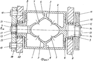
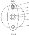
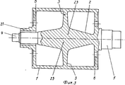
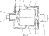
На фиг.1 показан цилиндр, продольное сечение в первой форме исполнения с опорными цапфами, опорами и регулирующим механизмом; на фиг.2 вид по стрелке А на фиг.1; на фиг.3 продольное сечение цилиндра во второй форме исполнения, но без опор и регулирующего механизма; на фиг.4 продольное сечение цилиндра в третьей форме выполнения. Figure 1 shows a cylinder, a longitudinal section in a first embodiment with support pins, supports and a control mechanism; figure 2 is a view along arrow A in figure 1; figure 3 is a longitudinal section of a cylinder in a second embodiment, but without supports and a regulating mechanism; figure 4 is a longitudinal section of a cylinder in a third embodiment.
Цилиндр выполнен в виде полого корпуса 1, в полости которого расположен в качестве оси корпус 2, имеющий форму тела вращения. Корпус 2, выполненный в виде тела вращения, имеет перемычки 3, проходящие соответственно от центрально расположенных по отношению к оболочке цилиндра осевых цапф 4 и 5 в осевом направлении к середине цилиндра и имеющие форму двух полых сдвоенных конусов, которые в центре цилиндра переходят в кольцевую поверхность 6. Перемычка 3 имеет выемки 7, а полый корпус 1 на обоих торцах имеет литейные отверстия 8 для фиксации формовочного стержня цилиндра и удаления формовочного песка. Захватные механизмы для передачи подлежащих печатанию листов на чертеже не показаны. Осевая цапфа 5 выполнена в виде приводной цапфы и расположена в опоре 10 рамы 9. Вне рамы 9 осевая цапфа 5 соединена посредством призматической шпонки 12 с зубчатым колесом 11. По центру осевой цапфы 5 закреплена винтами 14 торцевая шайба 13. The cylinder is made in the form of a
Другая осевая цапфа 4 выполнена в виде регулируемой цапфы, устанавливаемой в опоре 15, которая закреплена во фланце 16 и закрыта шайбой 17. Фланец 16 имеет удлиненное отверстие 18, через которое проходят регулировочные кулачки 19, разъемно соединенные с рамой 20. Осевая цапфа 4 расположена по центру трубчатой опорной цапфы 21. Опорная цапфа 21 установлена в опоре 22, смонтированной в раме 20. Захватные механизмы не показаны, потому что их конструкция не играет никакой роли для данного изобретения. Another
Опора 15 (фиг.2), в которой установлена осевая цапфа 4, может зажиматься в радиальном направлении с помощью регулировочных кулачков 19 над фланцем 16. The support 15 (figure 2), in which the
Вместо фланца 16 и регулировочных кулачков 19 могут применяться также и другие известные регулирующие средства. Instead of
На фиг.3 для наглядности изображения не показана опора, а также регулирующий механизм, поскольку они выполнены так, как это представлено на фиг.1 и 2. Согласно этой форме выполнения корпус 2 выполнен за одно целое в виде тела вращения, состоящего из двух усеченных конусов, проходящих, если смотреть от обеих осевых цапф 4, 5, по одной оси к центру цилиндра и сходящихся своими круговыми поверхностями 23, жестко соединенными перемычкой 3 с полым корпусом 1. Оба торца цилиндра также имеют несколько литейных отверстий 8, облегчающих отливку цилиндра или служащих для удаления формовочного песка. In Fig. 3, for clarity of the image, the support and the regulating mechanism are not shown, since they are made as shown in Figs. 1 and 2. According to this embodiment, the
Этот вариант выполнения цилиндра является особенно предпочтительным в том случае, когда стремятся получить простое выполнение литейного стержня и для цилиндров малого размера, в которых концентрация материала осевого корпуса не имеет значения. Является также возможным изготовить цилиндр сваркой из отдельных частей. Эти отдельные части состоят из корпуса 2, выполненного в виде тела вращения, диска с отверстиями, служащего перемычкой 3, а также двух дополнительных дисков с отверстиями, расположенных по торцам и приваренных к внутренней поверхности полого цилиндра 1. По меньшей мере, на одном торца приварена трубчатая опорная цапфа, направленная по оси наружу. This embodiment of the cylinder is particularly preferred in the case when they seek to obtain a simple embodiment of the casting rod and for small cylinders in which the concentration of the material of the axial body is not important. It is also possible to make the cylinder by welding from individual parts. These separate parts consist of a
Согласно форме выполнения (фиг.4), на которой опора, а также регулирующий механизм также не показаны, корпус 2 имеет форму тела вращения и выполнен за одно целое в виде двух деталей чашеобразной формы, проходящих, если смотреть от осевых цапф 4 и 5, в направлении к центру цилиндра и соединяющихся между собой своими краями 23 и через перемычку 3 жестко соединенных с полым корпусом 1. Оба торца цилиндра также имеют литьевые отверстия для обеспечения литья цилиндра и удаления формовочного песка. According to the form of execution (figure 4), on which the support, as well as the regulating mechanism are also not shown, the
Этот вариант выполнения является особенно предпочтительным для цилиндров большой длине и небольшого диаметра. This embodiment is particularly preferred for long cylinders and small diameters.
Кроме того, в случае особенно длинных цилиндров малого диаметра осевые цапфы можно расположить также со стороны привода по центру трубчатой опорной цапфы 21 и закрепить с помощью регулировочного механизма. In addition, in the case of particularly long cylinders of small diameter, the axial trunnions can also be located on the drive side in the center of the
Прогибы цилиндров для проводки бумаги различных размеров, обусловленные собственным весом, напряжением, создаваемым давлением, и приводными усилиями, можно в значительной мере устранить за счет конструкции согласно изобретению. Если, тем не менее, возникают явления незначительного прогиба, они могут компенсироваться осевыми цапфами, расположенными центрально в трубчатых опорных цапфах. Благодаря этому во время работы машины или в последующем можно обеспечить коррекцию положения передней кромки листа в отношении выпуклости или вогнутости. Deflections of cylinders for paper wiring of various sizes, due to their own weight, voltage, pressure, and drive forces, can be largely eliminated by the design according to the invention. If, however, slight bending phenomena occur, they can be compensated by axial trunnions located centrally in the tubular support trunnions. Due to this, during operation of the machine or subsequently, it is possible to provide correction of the position of the leading edge of the sheet with respect to convexity or concavity.
Благодаря конструкции с трубчатыми опорными цапфами с помощью имеющегося регулировочного устройства можно закрепить обе имеющиеся у цилиндра центрально расположенные осевые цапфы, что создает особенно большое преимущество для длинных цилиндров малого диаметра. Thanks to the design with tubular support pins, using the existing adjusting device, it is possible to fix both the centrally located axial pins on the cylinder, which creates a particularly great advantage for long cylinders with small diameters.
Claims (9)
Applications Claiming Priority (2)
| Application Number | Priority Date | Filing Date | Title |
|---|---|---|---|
| DEP4119824.7 | 1991-06-15 | ||
| DE4119824A DE4119824C1 (en) | 1991-06-15 | 1991-06-15 |
Publications (1)
| Publication Number | Publication Date |
|---|---|
| RU2042526C1 true RU2042526C1 (en) | 1995-08-27 |
Family
ID=6434053
Family Applications (1)
| Application Number | Title | Priority Date | Filing Date |
|---|---|---|---|
| SU925052069A RU2042526C1 (en) | 1991-06-15 | 1992-06-12 | Cylinder for running paper in web-fed rotary presses |
Country Status (5)
| Country | Link |
|---|---|
| US (1) | US5235912A (en) |
| EP (1) | EP0523367B1 (en) |
| JP (1) | JPH0780297B2 (en) |
| DE (3) | DE4119824C1 (en) |
| RU (1) | RU2042526C1 (en) |
Families Citing this family (15)
| Publication number | Priority date | Publication date | Assignee | Title |
|---|---|---|---|---|
| DE4335351C2 (en) * | 1993-10-16 | 2003-04-30 | Heidelberger Druckmasch Ag | Method and device for compensating register deviations in an offset rotary printing machine |
| DE4406572B4 (en) * | 1994-03-01 | 2004-06-03 | Heidelberger Druckmaschinen Ag | Rotary press |
| DE4431114C2 (en) * | 1994-09-01 | 1999-11-18 | Roland Man Druckmasch | Sheet-guiding drum body for a printing machine |
| ES2140289B1 (en) * | 1996-04-02 | 2000-08-16 | Windmoeller & Hoelscher | BUSHING FOR PRINTER CYLINDERS. |
| DE29623591U1 (en) * | 1996-04-02 | 1999-01-07 | Windmoeller & Hoelscher | Sleeve for printing rollers |
| DE19647069A1 (en) * | 1996-11-14 | 1998-05-20 | Heidelberger Druckmasch Ag | Hollow cast body e.g. printing machine cylinder preform |
| DE19647067A1 (en) * | 1996-11-14 | 1998-05-28 | Heidelberger Druckmasch Ag | Rotary printing machine |
| DE29701547U1 (en) | 1997-01-30 | 1997-03-20 | Voith Sulzer Papiermasch Gmbh | Roller for application device |
| EP1456032B1 (en) | 2001-12-19 | 2008-04-30 | Gallus Ferd. Rüesch Ag | Pressure cylinder in the form of a hollow cylinder made of metal |
| DE10250683B3 (en) * | 2002-10-31 | 2004-03-18 | Koenig & Bauer Ag | Manufacturing rotation body for printing machine involves fitting outer body with flow channel incision for heat-carrying medium to base body, fitting cover that covers flow channel to outer body |
| DE10250689B3 (en) * | 2002-10-31 | 2004-12-09 | Koenig & Bauer Ag | Production of a rotational body for a printing machine comprises forming a web made from a material which liquefies on heating on an inner side of an outer body or on the surface of the base body |
| DE10250686A1 (en) * | 2002-10-31 | 2004-05-19 | Koenig & Bauer Ag | Process for tempering a bale of a rotating body of a printing machine and rotating body of a printing machine with a bale |
| DE10250690B4 (en) | 2002-10-31 | 2006-03-02 | Koenig & Bauer Ag | Rotational body of a printing machine with a bale |
| DE10250691B4 (en) * | 2002-10-31 | 2006-03-02 | Koenig & Bauer Ag | Rotational body of a printing press with a base body |
| DE102013018582B4 (en) * | 2012-12-07 | 2021-11-25 | Heidelberger Druckmaschinen Intellectual Property Ag & Co. Kg | Printing machine and bearing for a shaft of a printing machine |
Family Cites Families (8)
| Publication number | Priority date | Publication date | Assignee | Title |
|---|---|---|---|---|
| US242058A (en) * | 1881-05-24 | sohtjrmann | ||
| BE356247A (en) * | 1927-12-08 | |||
| US2048005A (en) * | 1934-12-20 | 1936-07-21 | Hoe & Co R | Cylinder for printing machines |
| US3161125A (en) * | 1961-02-15 | 1964-12-15 | Beloit Iron Works | Adjustable crown roll |
| DE3005690A1 (en) * | 1980-02-15 | 1981-08-20 | M.A.N.- Roland Druckmaschinen AG, 6050 Offenbach | Bending roller for rotary printing machine - has lever at each end deflected by power cylinder to apply bending moment to ram |
| FI67675C (en) * | 1980-09-04 | 1985-05-10 | Frankenthal Ag Albert | CYLINDER FOR BANFORM MATERIAL BEARBETANDE MASKINER |
| US4487122A (en) * | 1983-11-04 | 1984-12-11 | Gravure Research Institute, Inc. | Deflection compensating roll for providing uniform contact pressure |
| DE3823846A1 (en) * | 1988-07-14 | 1990-01-18 | Heidelberger Druckmasch Ag | CYLINDERS IN THE PRINTING PLANT OF BOW ROTATION PRINTING MACHINES |
-
1991
- 1991-06-15 DE DE4119824A patent/DE4119824C1/de not_active Expired - Lifetime
- 1991-06-15 DE DE9116367U patent/DE9116367U1/de not_active Expired - Lifetime
-
1992
- 1992-06-06 EP EP92109612A patent/EP0523367B1/en not_active Expired - Lifetime
- 1992-06-06 DE DE59205937T patent/DE59205937D1/en not_active Expired - Fee Related
- 1992-06-12 US US07/897,815 patent/US5235912A/en not_active Expired - Fee Related
- 1992-06-12 RU SU925052069A patent/RU2042526C1/en active
- 1992-06-15 JP JP4155262A patent/JPH0780297B2/en not_active Expired - Lifetime
Non-Patent Citations (1)
| Title |
|---|
| Патент ФРГ N 3823846, кл. B 41F 13/08, 1990. * |
Also Published As
| Publication number | Publication date |
|---|---|
| EP0523367B1 (en) | 1996-04-10 |
| DE4119824C1 (en) | 1992-12-03 |
| US5235912A (en) | 1993-08-17 |
| EP0523367A1 (en) | 1993-01-20 |
| DE9116367U1 (en) | 1992-09-24 |
| JPH05169630A (en) | 1993-07-09 |
| JPH0780297B2 (en) | 1995-08-30 |
| DE59205937D1 (en) | 1996-05-15 |
Similar Documents
| Publication | Publication Date | Title |
|---|---|---|
| RU2042526C1 (en) | Cylinder for running paper in web-fed rotary presses | |
| JP2726051B2 (en) | Offset rotary printing press with a device for holding the printing cylinder | |
| JPH0780289B2 (en) | A printing device for an offset rotary printing press. | |
| EP0105477A2 (en) | Printing press with cylinder skew and throw off | |
| CN1212205A (en) | Printing press having cantilevered self-driven cylinders | |
| JPH02258260A (en) | Rotary press for rolled paper | |
| ZA888849B (en) | Laser engraving machine | |
| JP3644717B2 (en) | Printing unit | |
| KR890007895A (en) | Mandrel assembly for continuous printing on cylindrical containers | |
| US8356553B2 (en) | Print unit having blanket cylinder throw-off bearer surfaces and method | |
| JP6337017B2 (en) | Anti-pitch printing roller and sleeve | |
| EP1418048B1 (en) | Printing cylinder support unit with support ring | |
| ATE101083T1 (en) | SHEET TRANSPORT DRUM, WHICH AXIS IS MOVABLE AT ONE END AND IS MOVABLE IN TRANSLATION AT THE OTHER END. | |
| JPH0530183B2 (en) | ||
| US4164184A (en) | Compensating rotary screen supports | |
| JP2002031128A (en) | Bendable roll having composite shell | |
| JPH08506284A (en) | Cylinder axial distance adjustment device for printing machines | |
| JP2008534328A (en) | Cantilever blanket lifting mechanism | |
| US3881413A (en) | Pivoting rotary screen end ring mount | |
| US5286119A (en) | Bearing play adjusting assembly | |
| JP2513226Y2 (en) | Folding cylinder diameter adjusting device | |
| WO1991016201A1 (en) | Bearing device for side register | |
| JP3461119B2 (en) | Spindle drive in turret winder | |
| US2826142A (en) | Adjustable cylinder for duplicating machines | |
| JPS61237645A (en) | Regulator for rocking amount of roller in inking device of printer |