EP0519402B2 - Verfahren und Vorrichtung zum Versehen von Gegenständen mit einer schlauchförmigen Verpackungshülle - Google Patents
Verfahren und Vorrichtung zum Versehen von Gegenständen mit einer schlauchförmigen Verpackungshülle Download PDFInfo
- Publication number
- EP0519402B2 EP0519402B2 EP92110150A EP92110150A EP0519402B2 EP 0519402 B2 EP0519402 B2 EP 0519402B2 EP 92110150 A EP92110150 A EP 92110150A EP 92110150 A EP92110150 A EP 92110150A EP 0519402 B2 EP0519402 B2 EP 0519402B2
- Authority
- EP
- European Patent Office
- Prior art keywords
- seat
- product
- wrapping
- folding
- unloading
- Prior art date
- Legal status (The legal status is an assumption and is not a legal conclusion. Google has not performed a legal analysis and makes no representation as to the accuracy of the status listed.)
- Expired - Lifetime
Links
- 238000000034 method Methods 0.000 title claims description 11
- 239000000463 material Substances 0.000 claims description 8
- 238000007789 sealing Methods 0.000 claims description 7
- 238000011144 upstream manufacturing Methods 0.000 claims description 4
- 238000010438 heat treatment Methods 0.000 claims 2
- 238000004519 manufacturing process Methods 0.000 claims 1
- 238000009877 rendering Methods 0.000 claims 1
- 235000019504 cigarettes Nutrition 0.000 description 4
- 239000000853 adhesive Substances 0.000 description 2
- 230000001070 adhesive effect Effects 0.000 description 2
- 238000001035 drying Methods 0.000 description 1
- 230000001771 impaired effect Effects 0.000 description 1
- 238000012856 packing Methods 0.000 description 1
- 230000002093 peripheral effect Effects 0.000 description 1
Images


Classifications
-
- B—PERFORMING OPERATIONS; TRANSPORTING
- B65—CONVEYING; PACKING; STORING; HANDLING THIN OR FILAMENTARY MATERIAL
- B65B—MACHINES, APPARATUS OR DEVICES FOR, OR METHODS OF, PACKAGING ARTICLES OR MATERIALS; UNPACKING
- B65B11/00—Wrapping, e.g. partially or wholly enclosing, articles or quantities of material, in strips, sheets or blanks, of flexible material
- B65B11/06—Wrapping articles, or quantities of material, by conveying wrapper and contents in common defined paths
- B65B11/28—Wrapping articles, or quantities of material, by conveying wrapper and contents in common defined paths in a curved path, e.g. on rotary tables or turrets
- B65B11/30—Wrapping articles, or quantities of material, by conveying wrapper and contents in common defined paths in a curved path, e.g. on rotary tables or turrets to fold the wrappers in tubular form about contents
Definitions
- the present invention relates to a product wrapping method and a product wrapping device for producing tubular wrappings.
- the present invention relates to a method of wrapping parallelepiped products, such as packets or packs of cigarettes, to which the following description refers purely by way of example.
- a tubular wrapping is formed about the product by a wrapping device comprising a wrapping wheel conveyor having a number of equally-spaced peripheral radial seats for receiving a respective product for wrapping.
- the above known wrapping device normally also comprises a loading station, and a drive device for rotating the wrapping wheel in steps about its axis in such a manner as to successively arrest the seats in the loading station where the product and respective wrapping element (sheet or blank) are loaded on to the wheel. More specifically, as each seat on the wrapping wheel is arrested at the loading station, the wrapping element is normally fed in front of the inlet opening in the seat, and the product inserted radially through the inlet opening, so as to draw the wrapping element inside the seat and fold it in a U about the product. Once the product is fully inserted inside the seat, the wrapping element presents two longitudinal portions projecting outwards of the seat, and which are subsequently folded and connected one on top of the other to complete said tubular wrapping.
- a first of the two projecting portions, the trailing or upstream one in relation to the rotation direction of the wrapping wheel, is folded first by means of a mobile external folding device fitted to the loading station and operated before the wrapping wheel is started up again; while the second projecting portion, the leading or downstream one in relation to the rotation direction of the wrapping wheel, is folded on top of the first by a fixed folding device located outwards of the wrapping wheel and which contacts the second portion as the wrapping wheel is started up again.
- Said fixed folding device normally extends over a relatively wide arc about the edge of the wrapping wheel, for holding the second portion in position on top of the first pending stable connection of the second to the first portion either by gumming or, in the case of heat-sealable wrapping material, by sealing.
- the above known wrapping method presents several drawbacks, mainly due to the presence of said fixed folding device. More specifically, as a consequence of said second portion, once folded down on top of the first, rubbing against the surface of the fixed folding device, this must be so positioned as to allow a certain amount of clearance between itself and the outer edge of the wrapping wheel, to prevent the second portion from being in any way damaged, which clearance, however, inevitably results in imperfect folding of the second portion and in relatively weak contact pressure between the overlapping first and second portions.
- connection is normally impaired by the second portion having to be held in place by the fixed folding device during sealing.
- the fixed folding device must normally present an opening extending over the central portion of the overlapping portion for enabling passage of the sealing device, operation of which is thus obviously limited to the length of the opening as opposed to the entire length of the overlapping portion.
- the entire length of the overlapping portion may be sealed by arresting the wrapping wheel in such a position that the overlapping portion projects partially beyond the fixed folding device, with the free edge of the second portion held down by the end of the device. in this case, the overlapping portion is obviously sealed a given distance from the free edge of the second portion, the outer portion of which thus remains unsealed.
- the present invention also relates to a product wrapping device for producing tubular wrappings.
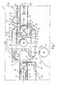
- Number 1 in Fig.1 indicates a wrapping device for producing tubular wrappings 2 for parallelepiped products 3 consisting, in the example shown, of packs of cigarettes.
- Device 1 comprises a wrapping wheel 4 cooperating with a known rotary unit 5 for supplying sheets of wrapping material 6, and driven by a powered shaft 7 so as to rotate about its axis 8 in direction 9 (anticlockwise in Fig.1) and so feed seats 10, equally spaced about the periphery of wheel 4, along a given path substantially tangent to supply unit 5 and extending through a loading station 11 wherein a product 3 and respective sheet 6 are inserted inside each seat 10, and through an unloading station 12 wherein product 3 and wrapping 2 are unloaded off wheel 4.
- wheel 4 consisting of a wrapping wheel for packs of cigarettes, comprises a substantially circular plate 13 connected angularly in known manner (not shown) to shaft 7, and having two diametrically-opposed seats 10, which are fed in 180° steps between stations 11 and 12, also diametrically opposed in relation to wheel 4, and past supply unit 5 located between stations 12 and 11 in direction 9.
- Loading station 11 comprises a feed channel 14 coplanar with plate 13, extending radially in relation to axis 8, and located in line with seat 10 in loading station 11.
- Loading station 11 also comprises a pusher 15 for successively feeding products 3 along channel 14 and into seat 10 in loading station 11.
- each product 3 encounters a respective sheet of wrapping material 6 fed beforehand in known manner on to wheel 4 by unit 5 and held on to the outer edge of plate 13, across seat 10, by two suction holes 16 and 17 on either side of seat 10.
- sheet 6 is thus also inserted and folded in a U about product 3, so as to present a first and second longitudinal portion 18 and 19 projecting from seat 10 and located respectively downstream and upstream in relation to direction 9.
- Loading station 11 also comprises a counterpusher 20 in turn comprising a linear actuator 21 supported on a plate 22 perpendicular to axis 8 and also supporting shaft 7 and channel 14.
- Actuator 21 presents an output rod 23 extending parallel to channel 14 between plates 13 and 22, and fitted on its free end with a crosspiece 24 parallel to axis 8 and extending, perpendicular to plate 22, along a central passage 25 formed through plate 13 perpendicular to plate 22 and coaxial with axis 8.
- Crosspiece 24 comes out of the opposite end of passage 25 to that facing plate 22, and is fitted on its free end with a curved appendix 26 extending over an arc of roughly 90° and in turn fitted on its free end with a second crosspiece 27 extending perpendicularly towards plate 22 and parallel to crosspiece 24.
- Crosspiece 27 together with crosspiece 24 and appendix 26 form a substantially U-shaped element 28 having its concave side facing plate 22 and integral with the free end of rod 23.
- central passage 25 presents a substantially square section, the sides of which are over twice as long as the distance between rod 23 and the longitudinal axis 29 of channel 14, and communicates with each seat 10 through an axial opening 30 formed in the end wall 31 of seat 10 and wider than crosspiece 27.
- central passage 25 presents two parallel elongated lateral recesses 32 extending on either side of central passage 25 and each assigned to a respective seat 10. More specifically, as shown in Fig.1, rod 23, element 28 and recesses 32 are so arranged that, when one of seats 10 is arrested in loading station 11, respective recess 32 is located parallel to axis 29, downstream from station 11 in direction 9, and facing rod 23, while respective crosspiece 27 intersects axis 29 and is aligned with respective opening 30.
- Device 1 comprises a folding assembly 33 defined by a first folding device 34, hereinafter referred to as the "fixed folding device”, and two folding devices 35, hereinafter referred to as "mobile folding devices".
- Fixed folding device 34 is assigned to loading station 11, and pivots in a fixed position on plate 22, outwards of wheel 4, for folding first portion 18 of sheet 6 on to respective product 3 in loading station 11.
- Each of mobile folding devices 35 is assigned to a respective seat 10, is mounted on wheel 4 so as to rotate with the same about axis 8, is located laterally in relation to respective seat 10, on the same side as second portion 19 of sheet 6, and provides for folding second portion 19 on top of first portion 18, and for maintaining portions 18 and 19 in said overlapping position for a given length of time.
- Fixed folding device 34 comprises a folding plate 36 fitted squarely to the end of a rod 37 connected to plate 22 so as to rotate, in relation to the same, about an axis (not shown) parallel to axis 8, and between an idle position wherein plate 36 is located outwards of station 11. and an operating position wherein plate 36 is located tangent to wheel 4, perpendicular to axis 29, and between the end of channel 14 and the edge of wheel 4, so as to engage portion 18 of sheet 6 of product 3 in loading station 11, and fold said portion 18 on to product 3.
- Each mobile folding device 35 comprises a folding plate 38 fitted squarely to the end of the output rod 39 of a linear actuator 40 supported on a respective powered shaft 41 parallel to axis 8 and connected for rotation to plate 13. Operation of shaft 41 and respective actuator 40 provides for moving plate 38, in relation to wheel 4, between a withdrawn idle position (Fig.2) wherein plate 38 does not interfere with respective seat 10, and a forward operating position (Fig.4) wherein plate 38 is located tangent to wheel 4, so as to engage portion 19 of sheet 6 of product 3 inside respective seat 10, and press portion 19 on to respective portion 18. As shown more clearly in Fig.4, plate 38 is so sized as to leave an end portion 42 of portion 19 exposed in said forward operating position.
- Unloading station 12 of device 1 comprises an unloading channel 43 supported, like channel 14, on plate 22, coplanar with plate 13, coaxial with axis 29, and having an input opening substantially tangent to the edge of wheel 4.
- Unloading station 12 presents a pusher 44 which, when product 3 is arrested in unloading station 12, provides for pushing product 3 out of seat 10 and along channel 43 into engagement with a known folding device 45, which, in known manner, folds and secures the end portions of tubular wrapping 2 on to the respective end surfaces of product 3.
- Pusher 44 comprises a linear actuator 46 supported in a fixed position on plate 22, to the side of channel 43, and located on the opposite side of channel 43 and wheel 4 in relation to plate 22.
- Actuator 46 presents an output rod 47 extending parallel to axis 29 and fitted squarely on its free end facing wheel 4 with an arm 48 extending parallel to plate 22 and perpendicularly intersecting axis 29.
- the free end of arm 48 is fitted integral with a crosspiece 49 substantially identical to crosspiece 27 and extending towards plate 22, parallel to axis 8.
- actuator 46 provides for moving crosspiece 49, along axis 29 and through opening 30 in respective seat 10, between an extracted idle position (Fig.5) wherein crosspiece 49 is located inside central passage 25, facing respective opening 30, and a withdrawn operating position (Fig.1) wherein crosspiece 49, by moving through opening 30 and radially through seat 10, penetrates a given way inside channel 43.
- unloading station 12 comprises a counterpusher 50 moving along channel 43, parallel to axis 29, and cooperating with pusher 44, when unloading products 3, for permanently controlling the position of products 3 along channel 43. More specifically, as shown in Fig.5, counterpusher 50 presents a head 51 designed to contact wrapping 2 of product 3 at end portion 42 of portion 19.
- head 51 by pressing portion 42 of portion 19 on to underlying portion 18, provides for ensuring firm connection of portions 18 and 19, and is preferably heated for fully drying the adhesive material between portions 18 and 19.
- head 51 is defined by a heat-sealing device as described and illustrated in co-pending Italian Patent Application n.BO91A 000222 filed concurrently by the present Applicant and to which full reference is made herein in the interest of full disclosure.
- wrapping wheel 4 is rotated about axis 8 so as to arrest one of seats 10 in loading station 11, and, as it is rotated, cooperates with unit 5, which feeds a sheet 6 over the input opening of said seat 10.
- fixed folding device 34 is moved into the operating position, so as to fold first portion 18, and is maintained in the operating position until mobile folding device 35 moves into the forward operating position, so as to fold second portion 19 on to first portion 18. More specifically, portion 19 is folded by moving rod 39 axially outwards, rotating shaft 41 (anticlockwise in Fig.4) so as to bring the free end of plate 38 into contact with portion 19, and by further rotating shaft 41 and simultaneously moving rod 39 inwards, so that plate 38 presses portion 19 on to portion 18, thus completing tubular wrapping 2.
- counterpusher 50 (Fig.5) is moved into the engaged position contacting end portion 42 of portion 19; mobile folding device 35 is restored to the idle position; and pusher 44 is moved from the extracted idle position into contact with product 3, and then, together with counterpusher 50, into the withdrawn operating position, so as to extract product 3 and tubular wrapping 2 from seat 10 (Fig.1) and feed them along channel 43, past folding device 45, and into an unloading position (not shown) wherein product 3, now fully wrapped, is unloaded in known manner (not shown) from channel 43.
- counterpusher 50 provides for firmly connecting portions 18 and 19 at end portion 42 of portion 19, which end portion projects beyond the free end of plate 38 of mobile folding device 35 in the forward operating position.
Landscapes
- Engineering & Computer Science (AREA)
- Mechanical Engineering (AREA)
- Basic Packing Technique (AREA)
- Wrapping Of Specific Fragile Articles (AREA)
Claims (9)
- Produktverpackungsverfahren zum Erzeugen von röhrenförmigen Packungen (2), welches Verfahren die Stufen umfaßt, die darin bestehen, dass ein Verpackungsförderer (4), der wenigstens einen nach außen offenen Verpackungssitz (10) für ein jeweiliges Produkt (3) aufweist, so betrieben wird, dass der Sitz (10) in eine gegebene Richtung (9) und längs eines Weges befördert wird, der durch eine Ladestation (11), an der das Produkt (3) in das Innere des Sitzes (10) geladen wird, und durch eine Entladestation (12) geht, an der das Produkt (3) vom Sitz (10) entladen wird, dass ein Produktverpackungselement (6) vor die Eingabeöffnung des Sitzes (10) an der Ladestation (11) befördert wird, dass das Produkt (3) in das Innere des Sitzes (10) so befördert wird, dass das Verpackungselement (6) U-förmig um das. Produkt (3) gefaltet wird, derart, dass ein erster und ein zweiter Längsteil (18, 19) des Verpackungselementes (6) vom Sitz (10) durch die Einlaßöffnung nach außen vorstehen, wobei der zweite Längsteil (19) bezüglich des ersten Längsteils (18) in Laufrichtung (9) oberhalb angeordnet ist, dass die Teile (18, 19) übereinander in eine überlappende Position gefaltet werden und dass die Teile (18, 19) in der überlappenden Position für eine gegebene Zeitdauer gehalten werden, wobei die beiden Teile (18, 19) in die überlappende Position dadurch gefaltet werden, dass zunächst der erste Teil (18) auf das Produkt (3) gefaltet wird und dann der zweite Teil (19) in die überlappende Position oben auf den ersten Teil (18) mittels einer Falteinrichtung (35) gefaltet wird, die am Verpackungsförderer (4) angebracht ist und sich in Bezug auf diesen in eine und aus einer Arbeitsposition bewegt, in der sie den zweiten Teil (19) in der überlappenden Position kontaktiert und darauf einen Druck ausübt, dadurch gekennzeichnet, dass die röhrenförmige Packung (2) an der Ladestation (11) gebildet wird, die Falteinrichtung (35) in der Arbeitsposition gehalten wird, bis der Sitz (10) die Entladestation (12) erreicht, die Falteinrichtung (35) so ausgebildet ist, dass sie den freien Endabschnitt (42) in Längsrichtung des zweiten Teils (19) in der Arbeitsposition freiliegend hält, die beiden überlappenden Teile (18, 19) an dem freien Endabschnitt (42) in Längsrichtung des zweiten Teils (19) an der Entladestation (12) in einem Stück miteinander verbunden werden.
- Verfahren nach Anspruch 1, dadurch gekennzeichnet, dass die beide überlappenden Teil (18, 19) in einem Stück miteinander dadurch verbunden werden, dass der freie Endabschnitt (42) in Längsrichtung des zweiten Teils (19) durch eine Entladeeinrichtung (50) an der Entladestation (12) erwärmt wird.
- Verfahren nach Anspruch 1 oder 2, dadurch gekennzeichnet, dass das Verpackungselement (6) aus einem heißsiegelfähigen Material besteht, wobei die beiden überlappenden Teile (18, 19) in einem Stück miteinander durch Heißsiegeln des freien Längsabschnitts (42) des zweiten Teils (19) auf den ersten Teil (18) durch die Entladeeinrichtung (50) an der Entladestation (12) verbunden werden.
- Verfahren nach einem der vorhergehenden Ansprüche, dadurch gekennzeichnet, dass die Bewegung der Falteinrichtung (35) in die Arbeitsposition eine erste Komponente im wesentlichen parallel zur Laufrichtung (9) und eine zweite Komponente im wesentlichen senkrecht zur Laufrichtung (9) hat.
- Verfahren nach einem der vorhergehenden Ansprüche, dadurch gekennzeichnet, dass der erste Teil (18) zunächst auf das Produkt (3) im Inneren des Sitzes (10) durch eine weitere Falteinrichtung (34) an der Ladestation (11) gefaltet wird.
- Produktverpackungsvorrichtung (1) zum Erzeugen von röhrenförmigen Packungen (2), welche Vorrichtung (1) einen schrittweise angetriebenen Verpackungsförderer (4), der wenigstens einen nach außen offenen Verpackungssitz (10) für ein jeweiliges Produkt (3) aufweist und sich in eine gegebene Richtung (9) bewegt, um den Sitz (10) entlang eines gegebenen Weges zu befördern, eine Ladestation (11) zum Laden des Produktes (3) in das Innere des Sitzes (10) und eine Entladestation (12) zum Entladen des Produktes (3) vom Sitz (10), wobei beide Stationen (11, 12) entlang des besagten Weges angeordnet sind, Einrichtungen zum Befördern eines Produktverpackungselementes (6) vor die Eingangsöffnung des Sitzes (10), erste Schiebeeinrichtungen (15, 20) zum Einsetzen des Verpackungselementes (6) und des jeweiligen Produktes (3) in das Innere des Sitzes (10), derart, dass das Verpackungselement (6) U-förmig um das Produkt (3) gefaltet wird, und ein erster und ein zweiter Längsteil (18, 19) des Verpackungselementes (6) durch die Eingangsöffnung vom Sitz (10) nach außen vorstehen, wobei der zweite Längsteil (19) bezüglich des ersten Längsteils (18) in Laufrichtung (9) oberhalb angeordnet ist, und Falteinrichtungen (33) umfaßt, um die Teile (18, 19) übereinander in eine überlappende Position zu falten und die Teile (18, 19) in der überlappenden Position für eine gegebene Zeitdauer zu halten, wobei die Falteinrichtung (33) eine Faltvorrichtung (35) umfasst, die am Verpackungsförderer (4) angebracht ist und sich diesbezüglich in eine Arbeitsposition und aus einer Arbeitsposition bewegt, in der sie den zweiten Teil (19), der sich außen am ersten- Teil (18) in der überlappenden Position befindet, kontaktiert und darauf einen Druck ausübt, dadurch dass die Falteinrichtung (33) eine weitere Faltvorrichtung (34) zum Falten des ersten Teils (18) auf das Produkt (3) in Inneren des Sitzes (10) an der Ladestation (11) umfasst, die weitere Faltvorrichtung (34) an der Ladestation (11) angebracht ist, die Faltvorrichtung (35) eine Platteneinrichtung (38) umfasst, die so ausgebildet ist, dass sie den zweiten Teil (19) kontaktiert, die Platteneinrichtung (38) so bemessen ist, dass sie den freien Endabschnitt (42) in Längsrichtung des zweiten Teils (19) freiliegend lässt, wenn die Faltvorrichtung (35) sich in der Arbeitsposition befindet, die Verpackungsvorrichtung eine Verbindungseinrichtung (51) umfasst, die die beiden überlappenden Teile (18, 19) in einem Stück miteinander am freien Endabschnitt (42) in Längsrichtung des zweiten Teils (19) zur Verbindung bringt, die Verbindungseinrichtung (51) an der Entladestation (12) angeordnet ist.
- Vorrichtung nach Anspruch 6, dadurch gekennzeichnet, dass die Verbindungseinrichtungen (51) ein Heizelement umfassen, dass so ausgebildet ist, dass es den freien Längsendabschnitt (42) des zweiten Teils (19) an der Entladestation (12) erfaßt.
- Vorrichtung nach Anspruch 6 oder 7, dadurch gekennzeichnet, dass das Verpackungselement (6) aus einem heißsiegelfähigen Material besteht, die Entladestation (12) Einrichtungen (50) zum Entladen der Produkte (3) und der jeweiligen Packungen (2) vom Sitz (10) umfaßt und die Verbindungseinrichtungen (51) eine Heißsiegeleinrichtung umfassen, die einen Teil der Entladeeinrichtungen (50) bildet.
- Vorrichtung nach einem der vorhergehenden Ansprüche 6 bis 8, dadurch gekennzeichnet, dass die Faltvorrichtung (35) eine erste Betätigungseinrichtung (41) und eine zweite Betätigungseinrichtung (40) umfaßt, um der Platteneinrichtung (38) bei deren Bewegung in die Arbeitsposition eine erste Bewegungskomponente im wesentlichen parallel zur Laufrichtung (9) und eine zweite Bewegungskomponente im wesentlichen senkrecht zur Laufrichtung (9) zu geben.
Applications Claiming Priority (2)
| Application Number | Priority Date | Filing Date | Title |
|---|---|---|---|
| ITBO910223A IT1246012B (it) | 1991-06-21 | 1991-06-21 | Metodo e dispositivo di incarto per la realizzazione di incarti tubolari di prodotti. |
| ITBO910223 | 1991-06-21 |
Publications (3)
| Publication Number | Publication Date |
|---|---|
| EP0519402A1 EP0519402A1 (de) | 1992-12-23 |
| EP0519402B1 EP0519402B1 (de) | 1996-11-20 |
| EP0519402B2 true EP0519402B2 (de) | 2004-04-07 |
Family
ID=11337608
Family Applications (1)
| Application Number | Title | Priority Date | Filing Date |
|---|---|---|---|
| EP92110150A Expired - Lifetime EP0519402B2 (de) | 1991-06-21 | 1992-06-16 | Verfahren und Vorrichtung zum Versehen von Gegenständen mit einer schlauchförmigen Verpackungshülle |
Country Status (6)
| Country | Link |
|---|---|
| US (1) | US5269117A (de) |
| EP (1) | EP0519402B2 (de) |
| JP (1) | JP2500249B2 (de) |
| BR (1) | BR9202353A (de) |
| DE (1) | DE69215276T3 (de) |
| IT (1) | IT1246012B (de) |
Families Citing this family (19)
| Publication number | Priority date | Publication date | Assignee | Title |
|---|---|---|---|---|
| IT1257834B (it) * | 1992-06-17 | 1996-02-13 | Gd Spa | Metodo e dispositivo per l'alimentazione di spezzoni di materiali di incarto in una macchina impacchettatrice di sigarette |
| IT1259800B (it) * | 1992-11-20 | 1996-03-26 | Gd Spa | Metodo e dispositivo per la realizzazione di sovraincarti tubolari di materiale termosaldabile. |
| US5480372A (en) * | 1993-12-10 | 1996-01-02 | General Mills, Inc. | Apparatus for folding and loading microwave popcorn bags into a fixture |
| US5463845A (en) * | 1993-12-10 | 1995-11-07 | General Mills, Inc. | Apparatus for folding, filling, and sealing microwave popcorn bags |
| US5463848A (en) * | 1993-12-10 | 1995-11-07 | General Mills, Inc. | Apparatus for folding and ejecting microwave popcorn bags from a fixture |
| US5507132A (en) * | 1993-12-10 | 1996-04-16 | General Mills, Inc. | Apparatus for opening microwave popcorn bags |
| IT1274821B (it) * | 1994-07-07 | 1997-07-25 | Gd Spa | Metodo di incarto per la formazione di pacchetti. |
| US5590814A (en) * | 1995-01-31 | 1997-01-07 | Johnson & Johnson Consumer Products, Inc. | Method and apparatus for loading bobbin cores |
| IT1279686B1 (it) * | 1995-11-28 | 1997-12-16 | Gd Spa | Gruppo di trasporto e saldatura per pacchetti. |
| IT1288130B1 (it) * | 1996-03-01 | 1998-09-10 | Sasib Spa | Macchina impacchettatrice, in particolare per sigarette, o simili |
| US5694738A (en) * | 1996-07-22 | 1997-12-09 | Tokyo Automatic Machinery Works, Ltd. | Body flap folding apparatus in packaging machine |
| IT1290696B1 (it) * | 1997-02-24 | 1998-12-10 | Gd Spa | Metodo e macchina per l'incarto di prodotti. |
| IT1304778B1 (it) * | 1998-07-06 | 2001-03-29 | Gd Spa | Macchina impacchettatrice. |
| DE10053666A1 (de) * | 2000-10-28 | 2002-05-08 | Topack Verpacktech Gmbh | Verfahren und Einrichtung zum Umhüllen von Verpackungen von Produkten der tabakverarbeitenden Industrie |
| ITBO20010346A1 (it) * | 2001-05-30 | 2002-11-30 | Gd Spa | Metodo ed unita' per la realizzazione di un incarto tubolare attorno ad un prodotto |
| DE102004046576A1 (de) * | 2004-09-23 | 2006-03-30 | Focke & Co.(Gmbh & Co. Kg) | Vorrichtung zum Umhüllen von Packungsgruppen |
| ITMI20050664A1 (it) * | 2005-04-15 | 2006-10-16 | Eurosicma S P A | Macchina a testa rotante per il confezionamento in film saldato |
| ITBO20050630A1 (it) * | 2005-10-20 | 2007-04-21 | Kpl Packlaging S P A | Metodo e macchina per l'imballaggio di gruppi di prodotti ordinati su uno o piu' strati |
| IT1390792B1 (it) * | 2008-07-29 | 2011-10-19 | Gd Spa | Metodo e unita di incarto per ripiegare un foglio di incarto attorno ad un articolo, costituito per esempio da un gruppo di sigarette. |
Citations (11)
| Publication number | Priority date | Publication date | Assignee | Title |
|---|---|---|---|---|
| US1875979A (en) † | 1930-03-01 | 1932-09-06 | Int Cigar Mach Co | Enveloping cigar |
| US1964411A (en) † | 1930-10-07 | 1934-06-26 | Int Cigar Mach Co | Cigar "cellophaning" machine |
| DE601667C (de) † | 1931-01-15 | 1934-08-22 | American Mach & Foundry | Verfahren und Maschine zur Herstellung eines Behaelters fuer Zigaretten u. dgl. |
| DE2124489C3 (de) † | 1971-05-18 | 1975-03-13 | Fr. Hesser Maschinenfabrik Ag, 7000 Stuttgart | Maschine zum Verpacken von Gegenständen insbesondere stangenförmiger Art |
| US4144695A (en) † | 1977-08-12 | 1979-03-20 | G. D. Societa Per Azioni | Device for folding the head portions of inner wrappers in a machine for packeting cigarettes into hinged-lid type packets |
| US4358920A (en) † | 1980-06-04 | 1982-11-16 | Lotte Co., Ltd. | Apparatus for wrapping a sheet article |
| DE3545884A1 (de) † | 1985-12-23 | 1987-07-02 | Focke & Co | Vorrichtung zum herstellen von (zigaretten-) packungen aus mindestens einem faltbaren zuschnitt |
| EP0304736A2 (de) † | 1987-08-28 | 1989-03-01 | Focke & Co. (GmbH & Co.) | Verfahren und Vorrichtung zum Einhüllen von insbesondere Zigaretten-Packungen |
| EP0137334B1 (de) † | 1983-09-14 | 1989-06-14 | Focke & Co. (GmbH & Co.) | Vorrichtung zum Herstellen von Packungen, insbesondere Zigaretten-Stangen |
| EP0374712A1 (de) † | 1988-12-21 | 1990-06-27 | SASIB S.p.A. | Einwickelvorrichtung, insbesondere für Zigarettenpackungen oder dgl. |
| US5003755A (en) † | 1989-09-14 | 1991-04-02 | G. D Societa' Per Azioni | Method and device for producing tubular wrappings |
Family Cites Families (4)
| Publication number | Priority date | Publication date | Assignee | Title |
|---|---|---|---|---|
| US2608039A (en) * | 1949-06-13 | 1952-08-26 | Abramowski Bruno | Machine for wrapping cigarettes |
| CH313164A (de) * | 1952-09-08 | 1956-03-31 | Hauni Werke Koerber & Co Kg | Vorrichtung zum Vereinigen von Zigaretten mit Mundstücken |
| BE757661A (fr) * | 1969-10-17 | 1971-04-16 | De La Rue Instr | Perfectionnements aux machines a enliasser |
| US3911654A (en) * | 1974-04-05 | 1975-10-14 | Sperry Rand Corp | Machine for forming a compact stack of crop material |
-
1991
- 1991-06-21 IT ITBO910223A patent/IT1246012B/it active IP Right Grant
-
1992
- 1992-06-16 DE DE1992615276 patent/DE69215276T3/de not_active Expired - Lifetime
- 1992-06-16 EP EP92110150A patent/EP0519402B2/de not_active Expired - Lifetime
- 1992-06-18 JP JP4216257A patent/JP2500249B2/ja not_active Expired - Lifetime
- 1992-06-18 US US07/900,598 patent/US5269117A/en not_active Expired - Lifetime
- 1992-06-22 BR BR929202353A patent/BR9202353A/pt not_active IP Right Cessation
Patent Citations (11)
| Publication number | Priority date | Publication date | Assignee | Title |
|---|---|---|---|---|
| US1875979A (en) † | 1930-03-01 | 1932-09-06 | Int Cigar Mach Co | Enveloping cigar |
| US1964411A (en) † | 1930-10-07 | 1934-06-26 | Int Cigar Mach Co | Cigar "cellophaning" machine |
| DE601667C (de) † | 1931-01-15 | 1934-08-22 | American Mach & Foundry | Verfahren und Maschine zur Herstellung eines Behaelters fuer Zigaretten u. dgl. |
| DE2124489C3 (de) † | 1971-05-18 | 1975-03-13 | Fr. Hesser Maschinenfabrik Ag, 7000 Stuttgart | Maschine zum Verpacken von Gegenständen insbesondere stangenförmiger Art |
| US4144695A (en) † | 1977-08-12 | 1979-03-20 | G. D. Societa Per Azioni | Device for folding the head portions of inner wrappers in a machine for packeting cigarettes into hinged-lid type packets |
| US4358920A (en) † | 1980-06-04 | 1982-11-16 | Lotte Co., Ltd. | Apparatus for wrapping a sheet article |
| EP0137334B1 (de) † | 1983-09-14 | 1989-06-14 | Focke & Co. (GmbH & Co.) | Vorrichtung zum Herstellen von Packungen, insbesondere Zigaretten-Stangen |
| DE3545884A1 (de) † | 1985-12-23 | 1987-07-02 | Focke & Co | Vorrichtung zum herstellen von (zigaretten-) packungen aus mindestens einem faltbaren zuschnitt |
| EP0304736A2 (de) † | 1987-08-28 | 1989-03-01 | Focke & Co. (GmbH & Co.) | Verfahren und Vorrichtung zum Einhüllen von insbesondere Zigaretten-Packungen |
| EP0374712A1 (de) † | 1988-12-21 | 1990-06-27 | SASIB S.p.A. | Einwickelvorrichtung, insbesondere für Zigarettenpackungen oder dgl. |
| US5003755A (en) † | 1989-09-14 | 1991-04-02 | G. D Societa' Per Azioni | Method and device for producing tubular wrappings |
Also Published As
| Publication number | Publication date |
|---|---|
| DE69215276T2 (de) | 1997-06-19 |
| EP0519402A1 (de) | 1992-12-23 |
| EP0519402B1 (de) | 1996-11-20 |
| BR9202353A (pt) | 1993-01-26 |
| ITBO910223A1 (it) | 1992-12-21 |
| DE69215276T3 (de) | 2004-11-18 |
| US5269117A (en) | 1993-12-14 |
| JPH07267207A (ja) | 1995-10-17 |
| JP2500249B2 (ja) | 1996-05-29 |
| IT1246012B (it) | 1994-11-07 |
| DE69215276D1 (de) | 1997-01-02 |
| ITBO910223A0 (it) | 1991-06-21 |
Similar Documents
| Publication | Publication Date | Title |
|---|---|---|
| EP0519402B1 (de) | Verfahren und Vorrichtung zum Versehen von Gegenständen mit einer schlauchförmigen Verpackungshülle | |
| EP0865987B1 (de) | Faltverfahren zum Bilden einer versiegelten schauchförmigen Umhüllung | |
| CN111874303B (zh) | 用于制造设有包装并容纳可冲泡材料的储袋的方法和设备 | |
| US6637175B2 (en) | Method and machine for wrapping infusion bags in outer envelopes | |
| EP1854726B1 (de) | Zigarettenverpackungsmaschine | |
| US5996318A (en) | Packet wrapping method and unit | |
| EP0795473B1 (de) | Vorrichtung zum Verpacken von Paketen | |
| US4648236A (en) | Packaging machine including a folding, sealing and conveying apparatus | |
| EP1452448B1 (de) | Verfahren zum Verpacken von Zigaretten in Weichpackungen | |
| EP0860358B1 (de) | Verfahren und Vorrichtung zum Umhüllen von Gegenständen | |
| US6000199A (en) | Wrapping method for producing packets | |
| GB2242665A (en) | Wrapping packets | |
| EP0751069B1 (de) | Verfahren und Vorrichtung zur Herstellung einer Verpackung für zylindrische Gegenstände, insbesondere Zigaretten oder dergleichen | |
| EP0806350B1 (de) | Verfahren zum Handhaben von Gegenständen | |
| US6904738B2 (en) | Method and unit for packing groups of products | |
| US5771666A (en) | Method of continuously wrapping products | |
| EP0792807B1 (de) | Verfahren und Vorrichtung zum Falten von Verpackungszuschnitten entlang vorgefalzten Linien | |
| EP0806347B1 (de) | Verfahren und Vorrichtung zum Falten von Endteilen schlauchförmiger Umhüllungen | |
| US6675556B2 (en) | Method and unit for forming a tubular wrapping about a product | |
| EP1899225B1 (de) | Verfahren und maschine zur herstellung einer verschlossenen verpackung um ein produkt und durch solch ein verfahren erhaltene verpackung | |
| EP1531127B1 (de) | Verfahren und Vorrichtung zum Herstellen einer schlauchförmigen Umhüllung | |
| EP1746029B1 (de) | Verfahren und Vorrichtung für das Wickeln von Artikeln | |
| US20050011164A1 (en) | Tampon packing method and machine | |
| EP0822142A1 (de) | Klappenfaltvorrichtung in einer Verpackungsmaschine | |
| JPH1059312A (ja) | ターレット型上包み機及びその包装方法 |
Legal Events
| Date | Code | Title | Description |
|---|---|---|---|
| PUAI | Public reference made under article 153(3) epc to a published international application that has entered the european phase |
Free format text: ORIGINAL CODE: 0009012 |
|
| AK | Designated contracting states |
Kind code of ref document: A1 Designated state(s): DE FR GB IT |
|
| 17P | Request for examination filed |
Effective date: 19930621 |
|
| 17Q | First examination report despatched |
Effective date: 19950124 |
|
| GRAH | Despatch of communication of intention to grant a patent |
Free format text: ORIGINAL CODE: EPIDOS IGRA |
|
| GRAH | Despatch of communication of intention to grant a patent |
Free format text: ORIGINAL CODE: EPIDOS IGRA |
|
| GRAA | (expected) grant |
Free format text: ORIGINAL CODE: 0009210 |
|
| AK | Designated contracting states |
Kind code of ref document: B1 Designated state(s): DE FR GB IT |
|
| REF | Corresponds to: |
Ref document number: 69215276 Country of ref document: DE Date of ref document: 19970102 |
|
| ET | Fr: translation filed | ||
| ITF | It: translation for a ep patent filed | ||
| PLBQ | Unpublished change to opponent data |
Free format text: ORIGINAL CODE: EPIDOS OPPO |
|
| PLBI | Opposition filed |
Free format text: ORIGINAL CODE: 0009260 |
|
| 26 | Opposition filed |
Opponent name: FOCKE & CO. (GMBH & CO.) Effective date: 19970613 |
|
| PLBF | Reply of patent proprietor to notice(s) of opposition |
Free format text: ORIGINAL CODE: EPIDOS OBSO |
|
| PLBF | Reply of patent proprietor to notice(s) of opposition |
Free format text: ORIGINAL CODE: EPIDOS OBSO |
|
| PLBF | Reply of patent proprietor to notice(s) of opposition |
Free format text: ORIGINAL CODE: EPIDOS OBSO |
|
| PLAW | Interlocutory decision in opposition |
Free format text: ORIGINAL CODE: EPIDOS IDOP |
|
| APAC | Appeal dossier modified |
Free format text: ORIGINAL CODE: EPIDOS NOAPO |
|
| APAE | Appeal reference modified |
Free format text: ORIGINAL CODE: EPIDOS REFNO |
|
| APAC | Appeal dossier modified |
Free format text: ORIGINAL CODE: EPIDOS NOAPO |
|
| APAE | Appeal reference modified |
Free format text: ORIGINAL CODE: EPIDOS REFNO |
|
| REG | Reference to a national code |
Ref country code: GB Ref legal event code: IF02 |
|
| APCC | Communication from the board of appeal sent |
Free format text: ORIGINAL CODE: EPIDOS OBAPO |
|
| APAC | Appeal dossier modified |
Free format text: ORIGINAL CODE: EPIDOS NOAPO |
|
| PLAW | Interlocutory decision in opposition |
Free format text: ORIGINAL CODE: EPIDOS IDOP |
|
| RAP2 | Party data changed (patent owner data changed or rights of a patent transferred) |
Owner name: G.D SOCIETA' PER AZIONI |
|
| PUAH | Patent maintained in amended form |
Free format text: ORIGINAL CODE: 0009272 |
|
| STAA | Information on the status of an ep patent application or granted ep patent |
Free format text: STATUS: PATENT MAINTAINED AS AMENDED |
|
| 27A | Patent maintained in amended form |
Effective date: 20040407 |
|
| AK | Designated contracting states |
Kind code of ref document: B2 Designated state(s): DE FR GB IT |
|
| ET3 | Fr: translation filed ** decision concerning opposition | ||
| APAH | Appeal reference modified |
Free format text: ORIGINAL CODE: EPIDOSCREFNO |
|
| PGFP | Annual fee paid to national office [announced via postgrant information from national office to epo] |
Ref country code: GB Payment date: 20070628 Year of fee payment: 16 |
|
| PGFP | Annual fee paid to national office [announced via postgrant information from national office to epo] |
Ref country code: IT Payment date: 20070628 Year of fee payment: 16 |
|
| PGFP | Annual fee paid to national office [announced via postgrant information from national office to epo] |
Ref country code: FR Payment date: 20070618 Year of fee payment: 16 |
|
| GBPC | Gb: european patent ceased through non-payment of renewal fee |
Effective date: 20080616 |
|
| REG | Reference to a national code |
Ref country code: FR Ref legal event code: ST Effective date: 20090228 |
|
| PG25 | Lapsed in a contracting state [announced via postgrant information from national office to epo] |
Ref country code: GB Free format text: LAPSE BECAUSE OF NON-PAYMENT OF DUE FEES Effective date: 20080616 |
|
| PG25 | Lapsed in a contracting state [announced via postgrant information from national office to epo] |
Ref country code: FR Free format text: LAPSE BECAUSE OF NON-PAYMENT OF DUE FEES Effective date: 20080630 Ref country code: IT Free format text: LAPSE BECAUSE OF NON-PAYMENT OF DUE FEES Effective date: 20080616 |
|
| PLAB | Opposition data, opponent's data or that of the opponent's representative modified |
Free format text: ORIGINAL CODE: 0009299OPPO |
|
| PGFP | Annual fee paid to national office [announced via postgrant information from national office to epo] |
Ref country code: DE Payment date: 20100629 Year of fee payment: 19 |
|
| PG25 | Lapsed in a contracting state [announced via postgrant information from national office to epo] |
Ref country code: DE Free format text: LAPSE BECAUSE OF NON-PAYMENT OF DUE FEES Effective date: 20120103 |
|
| REG | Reference to a national code |
Ref country code: DE Ref legal event code: R119 Ref document number: 69215276 Country of ref document: DE Effective date: 20120103 |