EP0519220A1 - Ballast avec temps de chauffage commandé - Google Patents
Ballast avec temps de chauffage commandé Download PDFInfo
- Publication number
- EP0519220A1 EP0519220A1 EP92108303A EP92108303A EP0519220A1 EP 0519220 A1 EP0519220 A1 EP 0519220A1 EP 92108303 A EP92108303 A EP 92108303A EP 92108303 A EP92108303 A EP 92108303A EP 0519220 A1 EP0519220 A1 EP 0519220A1
- Authority
- EP
- European Patent Office
- Prior art keywords
- gas discharge
- capacitor
- voltage
- discharge lamp
- parallel
- Prior art date
- Legal status (The legal status is an assumption and is not a legal conclusion. Google has not performed a legal analysis and makes no representation as to the accuracy of the status listed.)
- Withdrawn
Links
Images


Classifications
-
- H—ELECTRICITY
- H05—ELECTRIC TECHNIQUES NOT OTHERWISE PROVIDED FOR
- H05B—ELECTRIC HEATING; ELECTRIC LIGHT SOURCES NOT OTHERWISE PROVIDED FOR; CIRCUIT ARRANGEMENTS FOR ELECTRIC LIGHT SOURCES, IN GENERAL
- H05B41/00—Circuit arrangements or apparatus for igniting or operating discharge lamps
- H05B41/14—Circuit arrangements
- H05B41/26—Circuit arrangements in which the lamp is fed by power derived from dc by means of a converter, e.g. by high-voltage dc
- H05B41/28—Circuit arrangements in which the lamp is fed by power derived from dc by means of a converter, e.g. by high-voltage dc using static converters
- H05B41/295—Circuit arrangements in which the lamp is fed by power derived from dc by means of a converter, e.g. by high-voltage dc using static converters with semiconductor devices and specially adapted for lamps with preheating electrodes, e.g. for fluorescent lamps
Definitions
- the invention relates to a ballast with the features of the preamble of claim 1.
- ballasts if the gas discharge lamp is connected in parallel to the capacitor of the series resonant circuit, voltages can be generated in this way which are sufficiently high to ignite a gas discharge lamp with cold electrodes. It has been found that when the gas discharge lamp is ignited with cold electrodes, the service life of the gas discharge lamp is considerably shortened, in that the service life is significantly influenced by the number of switch-on processes.
- the known circuit arrangement contains a series resonance circuit consisting of a frequency-determining inductor and a capacitor, which are connected together to the output of an inverter whose operating frequency is matched to the resonance frequency.
- the gas discharge lamp with its two lamp filaments is connected in parallel with the capacitor.
- the frequency-determining capacitor is not directly parallel to the gas discharge lamp, but rather is connected in series with a two-pole circuit, which changes its impedance value depending on the time after a voltage has appeared at its two connections. Immediately after switching on the voltage, the two-pole has a small impedance, which gradually increases and is finally switched to a third value.
- Another circuit for preheating the gas discharge lamp before applying the ignition voltage is known from DE-OS 38 35 533.
- the frequency-determining capacitor is divided into the series circuit of two individual capacitors, an NTC resistor with a parallel ohmic resistor being connected between the capacitors.
- the NTC resistor together with the ohmic resistor is supposed to be a resistance characteristic have, which is the reverse of the resistance characteristic of the heating filament of the gas discharge lamp.
- the two-pole circuit which is said to lead to controlled preheating, is also in the series resonant circuit when the preheating is switched off. It also influences the quality of the resonant circuit and thus the operating voltage on the lamp.
- the characteristic curve of the temperature-dependent resistors must be matched to the lamp type, so that the respective ballast can only be used for one lamp type.
- Another circuit for preheating the gas discharge lamp according to DE-OS 40 05 776 uses a series resonance circuit, but in this series resonance circuit the gas discharge lamp is not in parallel but in series with the frequency-determining capacitor.
- a bridge rectifier is connected in parallel to the gas discharge lamp, in the bridge diagonal of which there is a bipolar transistor which is connected to the circuit ground with a connection.
- the bipolar transistor is controlled using a control signal that comes from the inverter.
- the transistor When the transistor is turned on, the current coming from the inverter flows through both heating filaments, while on the other hand the voltage across the lamp is limited to the forward voltage of the bridge rectifier and the bipolar transistor, so that it cannot ignite under any circumstances. After preheating, the bipolar transistor is switched off, and the full inverter voltage can appear on the preheated heating coils. This ignites the gas discharge lamp.
- the control of the bipolar transistor starts at least between the inverter and the gas discharge lamp one place a galvanic isolation, because the device for preheating is from the point of view of the gas discharge lamp not a two- but a four-pole, which contains galvanic connections.
- the circuit can be used universally for different lamps, but is complex because of the galvanic isolation between the output of the inverter and the gas discharge lamp.
- the design of the preheating device as a two-pole system has the advantage that it does not require any further galvanic connection in the form of a control line, but rather all control and supply voltages are derived from the voltage drop across the gas discharge lamp. Since there are no other electronic components in the new circuit arrangement between the gas discharge lamp and the frequency-determining capacitor, the damping conditions in the burning mode are very simple and manageable.
- the parallel connection of the preheating device to the capacitor also ensures, without further ado, any power supply to the preheating device that may be required in the switched-off state, because the full operating voltage is also available to the preheating device. As a result of the negative differential internal resistance of gas discharge lamps, this In this way, a largely frequency-independent voltage stabilization is achieved at the same time, thereby achieving a fairly stable supply voltage for the preheating device.
- both the frequency-determining capacitor and the preheating device are switched on at the same end of each heating filament, a heating current flows through the lamp filament both in the preheating mode and in the later lamp mode, which in the preheating mode mainly due to the current through the preheating device and in the later burning mode mainly through the Reactive current is caused in the capacitor.
- the preheating device advantageously contains at least one controllable electronic component which has a control input and is connected in parallel with its connections to the connecting terminals of the preheating device.
- Both electronic components that can be operated with an alternating voltage and those that require a direct voltage supply can be considered as electronic components.
- the control input of the controllable component is at a time stage which, regardless of its circuit design, ensures that the controllable component immediately after the appearance of a voltage on the heating coils and thus on the connections of the preheating device has a low impedance value and after a predetermined time a high one Has impedance value.
- An electronic component that is particularly well suited is an enhancement type field effect transistor, because in this case the time stage can be designed to be extremely high-resistance.
- the field effect transistor requires practically no control power, since it only has to be switched twice for the ignition and subsequent burning of the gas discharge lamps, namely once in the conductive state and after the preheating for ignition in the blocked state. Even the currents required to reload the gate are extremely low under these circumstances because the switching process can easily be done slowly.
- the time stage expediently contains an RC element as the time-determining element, with which the heating time can be very easily adapted to the respective heating current.
- an inverter can also be located between the RC element and the control input of the controllable component, depending on which connection of the RC element to the supply voltage of the preheating device is considered appropriate.
- a varistor In order to protect the controllable component against overvoltages and thus against damage in the event of a fault a varistor can be connected in parallel to this component, which becomes conductive in the event of overvoltages.
- the new circuit arrangement is also suitable for operating a series circuit comprising two gas discharge lamps, in which case the preheating device and the frequency-determining capacitor lie parallel to the overall series circuit with two gas discharge lamps.
- the heating of the two heating filaments, which is located at the junction of the two gas discharge lamps, takes place with the aid of an additional winding on the choke of the series resonance circuit in the power supply line to the two gas discharge lamps.
- This heater can remain switched on at all times since it requires only relatively little electricity and otherwise has no influence on the burning operation of the lamps.
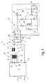
- a primary winding 21 of a further transformer 22 is connected, which also carries a secondary winding 23.
- the purpose of the secondary winding 23 is explained in connection with FIG. 2.
- the primary winding 21 is the actual frequency-determining inductance, since it is large compared to the inductance of the winding 13.
- the series circuit comprising the transformer 12 and the transformer 22 also contains a capacitor 24, which has the task of suppressing any DC component present at the output 8. Otherwise, the capacitor 24 should have as little influence as possible on the function of the circuit.
- the heating coil 3 which has two connections 25 and 26, is connected to the capacitor 24 with its connection 25.
- the other heating coil 24 also has two connections 27 and 28. Its connection 27 leads to the output connection 9.
- a frequency-determining capacitor 29 Parallel to the gas discharge lamp 2 is a frequency-determining capacitor 29 which is connected to the ends 26 and 28.
- the frequency-determining capacitor 29 forms, together with the total inductance from the primary winding 13 and the primary winding 21, a series resonant circuit which defines the operating frequency of the inverter 5 and at the same time ensures a resonance voltage increase at the gas discharge lamp 2.
- the capacitor 24 is large compared to the capacitor 29, so that it plays practically no role as a frequency-determining element in the series resonant circuit.
- a preheating device 31 which is designed as a two-pole system with two connections 32 and 33, lies parallel to the capacitor 29.
- the preheater 31 includes a bridge rectifier 34, the AC voltage inputs of which are connected to the terminals 33 and 32, i. H. it is connected in parallel to the frequency-determining capacitor 29 and thus also to the gas discharge lamp 2.
- a varistor 37 is connected in parallel to the latter, which is connected to the source and drain electrodes of the MOS field.
- the MOS FET 36 is controlled at its gate by a time stage 38.
- This contains a series circuit of an ohmic resistor 39 and a Zener diode 41, which is connected between the gate and the source electrode of the field effect transistor 36, while the resistor 39 to the hot end of the resistor 35 or the corresponding DC voltage output of the Bridge rectifier 34 leads.
- a bipolar transistor 42 is present parallel to the Z diode 41, the emitter of which leads to the anode of the Z diode 41 and the collector of which leads to the base of the field effect transistor 36 and the cathode of the Z diode 41.
- a further Z-diode 43 goes from the base of the NPN transistor 42 to a time-determining capacitor 44, specifically the Z-diode 43 is connected to the capacitor 44 with the cathode.
- the time-determining capacitor 44 is charged with the aid of a likewise time-determining resistor 45, which connects the cathode of the Zener diode 43 to the hot end of the resistor 39.
- a discharge resistor 46 is finally connected in parallel with the capacitor 44.
- the ballast 1 described so far works as follows: When the mains voltage is switched on at the power supply inputs 6 and 7, the inverter 5 begins to work and generates an AC voltage at its output 8 with respect to the circuit ground 11, the frequency of which, due to the feedback via the windings 14 and 15, depends on the resonance frequency of the one connected to the output 8 Series resonance circuit is defined, the predominantly frequency-determining elements of the capacitor 29 and the total inductance from the windings 13 and 21. This creates an alternating voltage on the two heating filaments 3, 4 of the gas discharge lamp 2, which also reaches the preheating device 31 because its two connections 32 and 33 are parallel to the gas discharge lamp 2.
- the MOS-FET 36 is turned on, so that the bridge rectifier 34 is practically loaded with the resistor 35 at its output connections. As a result, the resistor 35 is electrically connected to the gas discharge lamp 2 in parallel.
- the output voltage from the inverter 5 consequently leads to a heating current through the heating coils 3 and 4.
- the current coming from the connection 8 flows through the windings 13 and 21, the capacitor 24, the heating coil 3 and into the bridge rectifier 34 Since the bridge rectifier is bridged on the output side by the resistor 35 - the MOS-FET 36 is controlled - the current flows via the bridge rectifier 34 through the heating coil 4 to the terminal 9. At the same time, this reduces the circuit quality of the series resonant circuit and the longitudinal voltage on the gas discharge lamp 2 pulled down to values below the ignition voltage of the gas discharge lamp 2.
- the mentioned switching state of the MOS-FET 36 arises, as mentioned, immediately after the occurrence of a longitudinal voltage on the gas discharge lamp 2, because the gate of the MOS fat 36 is immediately subjected to a corresponding bias voltage via the resistor 39, the size of which is limited to a suitable value by the Zener diode 41. In the present case shown, a positive supply voltage with a stabilized size thus reaches the gate of the field effect transistor 36.
- the bipolar NPN transistor 42 is blocked immediately after a voltage is switched on between the two connections 32 and 33 of the preheater 31, because the capacitor 44 at its base is discharged via the resistor 46.
- the supply voltage for the RC element is equal to the voltage drop across the drain resistor 35 of the controlled MOS-FET 36.
- the capacitor 44 consequently charges over time until its voltage is greater than the forward voltage of the Zener diode 43 plus the base emitter voltage of the transistor 42 becomes.
- the transistor 42 is turned on and thereby the gate of the field-effect transistor 36 is short-circuited to its source connection.
- the field effect transistor 36 blocks, i. H. the resistor 35 is switched off by the gas discharge lamp 2.
- the omitted load on the series resonant circuit causes the capacitor 29 to jump, the voltage which is greater than the output voltage of the inverter 5, measured between the output 8 and the output 9 due to the resonance increase.
- the increase in the longitudinal voltage at the gas discharge lamp 2 leads directly to it Ignite, but now with preheated heating coils 3 and 4, d. H. there is a warm start.
- the only load which, in this operating situation, is still parallel to the frequency-determining capacitor 29 results from the base and collector currents of the transistor 42, which increases with respect to the lamp current is neglect. It is of the order of less than 1 mA, while the current through the gas discharge lamp 2 is greater by a factor of 1000.
- the preheating device 31 can thus be completely neglected from an electrical point of view as soon as the gas discharge lamp 2 has ignited.
- the impedance value between the connections 32 and 33 is negligibly small compared to the internal resistance of the burning gas discharge lamp 2.
- the operating voltage of the gas discharge lamp 2 ensures that the state of charge of the capacitor 44 is maintained and thus the transistor 42 is also turned on while the gas discharge lamp 2 should burn.
- the capacitor 44 can discharge via the resistor 46.
- the discharge time constant is expediently in the range of the cooling time constants of the heating filaments 3 and 4. If the device is switched on again immediately after switching off, the preheating device 31 remains inactive and the output voltage at the inverter 5 immediately rises to the ignition voltage value, around the gas discharge lamp 2 when the heating filaments 3 and 4 are still warm to ignite.
- the switch-off time is so long that the heating coils 3, 4 cool down, the time-determining capacitor 44 is also discharged via the resistor 46, so that the game explained at the beginning is repeated as soon as the voltage is connected to the power supply inputs 6 and 7.
- Fig. 2 shows the use of the new ballast when operating two gas discharge lamps 2a and 2b. If the same component appears in the circuit according to FIG. 2 as in the circuit diagram according to FIG. 1, the same reference numerals are used for this and their function is not described again. For the heating coil of the gas discharge lamp 2a, the same reference numerals are used as for the gas discharge lamp 2 from FIG. 1.
- the gas discharge lamp 2b has the same structure, which is why the reference symbols are expanded by the index b.
- the heating coil 3 is located in the electrical connection between the coupling capacitor 24 and the frequency-determining capacitor 29.
- the heating coil 4 is connected at its end 24 to the secondary winding 23 already explained, while the other end 28 leads to the end 26b of the heating coil 3b. From here there is a connection to the secondary winding 23 via the end 25b; in other words, the series connection of both heating coils 4 and 3b is parallel to the winding 23.
- the heating coil 4b is connected in the same way as the heating coil 4 according to FIG. 1, i.e. H. at one end it is connected to the frequency-determining capacitor 29 and at the other end to the terminal 9.
- the preheating device 31 behaves as already described and generates a heating current in the heating coil 3 and the heating coil 4b, since these two heating coils are connected to one another via the drain resistor 35.
- the alternating current generated in this way by the transformer 22 also generates an alternating current in the secondary winding 23 thereof, which applies current to the two heating coils 4 and 3b connected in series, which also heats them.
- the preheating device 31 jumps to the high impedance value.
- the inverter 5 contains two power transistors 51 and 52 connected to form a half-bridge.
- the two power transistors 51 and 52 in the exemplary embodiment shown are NPN transistors, are connected in series and lie between a positive supply voltage and the circuit ground 11.
- the positive supply voltage U b is generated in a known manner from the rectified mains voltage and sifted through a capacitor. It is of the order of 350 V.
- Each of the two transistors 51 and 52 is bridged from its collector to its emitter by means of a free-wheeling diode 53 and 54, respectively.
- the secondary winding 14 is located on the base-emitter path of the transistor 51 and the winding 15 on the base-emitter path of the transistor 53.
- a start-up aid which contains an RC element made up of the resistor 55 and a capacitor 56 which is connected to ground by the positive supply voltage U b .
- a protective resistor 57 connected in series, which has the task of ensuring a current limitation when the capacitor 56 is discharged.
- the junction between the two resistors 55 and 57 is via a diac 58 at the base of transistor 51.
- a diode 59 which is also connected to the connection point between the resistors 55 and 57, stops the starting aid as soon as the inverter 5 is working.
- the two transistors 51 and 52 are initially blocked because they do not receive a positive base bias.
- the capacitor 56 can be charged via the resistors 55 and 57 until its voltage is greater than the voltage of the diac 58, which then breaks down and delivers a positive current pulse to the base of the transistor 51.
- capacitor 56 is discharged via diode 59 and protective resistor 57. This will ensure that during the other half-wave, the time is not sufficient to charge the capacitor 56 up to the forward voltage of the diac 58 via the resistor 55. As soon as the inverter 5 has swung once, the capacitor 56 never again reaches a voltage which is sufficient to ignite the diac 58.
- the protective resistors familiar to the person skilled in the art are omitted in the base and emitter leads of the transistors 51 and 52, as well as resistors and capacitors, which have the sole purpose of suppressing the circuit. There are also no protective measures for the inverter 5 against HF vibrations in the case of an interruption in the series resonant circuit.
Landscapes
- Circuit Arrangements For Discharge Lamps (AREA)
Applications Claiming Priority (2)
| Application Number | Priority Date | Filing Date | Title |
|---|---|---|---|
| DE19914119775 DE4119775A1 (de) | 1991-06-15 | 1991-06-15 | Vorschaltgeraet mit gesteuerter heizzeit |
| DE4119775 | 1991-06-15 |
Publications (1)
| Publication Number | Publication Date |
|---|---|
| EP0519220A1 true EP0519220A1 (fr) | 1992-12-23 |
Family
ID=6434024
Family Applications (1)
| Application Number | Title | Priority Date | Filing Date |
|---|---|---|---|
| EP92108303A Withdrawn EP0519220A1 (fr) | 1991-06-15 | 1992-05-16 | Ballast avec temps de chauffage commandé |
Country Status (2)
| Country | Link |
|---|---|
| EP (1) | EP0519220A1 (fr) |
| DE (1) | DE4119775A1 (fr) |
Cited By (5)
| Publication number | Priority date | Publication date | Assignee | Title |
|---|---|---|---|---|
| FR2718598A1 (fr) * | 1994-04-06 | 1995-10-13 | Hamm Valery | Dispositif de contrôle d'un tube fluorescent. |
| WO1998024277A1 (fr) * | 1996-11-24 | 1998-06-04 | Jbp Technologies Ltd. | Procede et circuits de demarreur pour l'allumage et la mise en oeuvre de lampes a decharges |
| EP1276355A2 (fr) * | 2001-07-10 | 2003-01-15 | Patent-Treuhand-Gesellschaft für elektrische Glühlampen mbH | Circuit ballast pour determiner la puissance de préchauffage |
| DE20303594U1 (de) * | 2002-12-23 | 2004-05-06 | Steca Batterieladesysteme und Präzisionselektronik GmbH | Vorheizschaltung, insbesondere für eine Entladungslampe |
| CN100346674C (zh) * | 2002-08-19 | 2007-10-31 | 松下电工株式会社 | 放电灯启动装置 |
Families Citing this family (3)
| Publication number | Priority date | Publication date | Assignee | Title |
|---|---|---|---|---|
| DE4328306A1 (de) * | 1993-08-23 | 1994-03-17 | Spindler Bernhard Dipl Ing | Schaltungsanordnung zur Einstellung und Regelung des Betriebszustandes von Niederdruckentladungslampen im Hochfrequenz- und Niederfrequenzbetrieb |
| DE9404469U1 (de) * | 1994-03-16 | 1994-11-10 | Trilux Lenze Gmbh & Co Kg | Mehrlampen-Vorschaltgerät für Entladungslampen |
| DE29605967U1 (de) * | 1996-03-30 | 1996-06-13 | Trilux Lenze Gmbh & Co Kg | Leuchtstofflampen-Vorschaltgerät |
Citations (5)
| Publication number | Priority date | Publication date | Assignee | Title |
|---|---|---|---|---|
| US4227118A (en) * | 1977-12-01 | 1980-10-07 | The General Electric Company Limited | Circuits for operating electric discharge lamps |
| DE3401653A1 (de) * | 1983-01-20 | 1984-07-26 | Zumtobel Ag, Dornbirn | Wechselrichterschaltung zum betrieb von gasentladungslampen |
| US4647817A (en) * | 1984-11-16 | 1987-03-03 | Patent-Truehand Gesellschaft m.b.H. | Discharge lamp starting circuit particularly for compact fluorescent lamps |
| DE3835533A1 (de) * | 1988-10-19 | 1990-04-26 | Hueco Gmbh | Elektronische starteinrichtung zum zuenden von leuchtstofflampen im hochfrequenzbetrieb |
| DE3901111A1 (de) * | 1989-01-16 | 1990-07-19 | Patent Treuhand Ges Fuer Elektrische Gluehlampen Mbh | Schaltungsanordnung zum betrieb von entladungslampen |
Family Cites Families (4)
| Publication number | Priority date | Publication date | Assignee | Title |
|---|---|---|---|---|
| DE2122411A1 (de) * | 1971-05-06 | 1972-11-30 | Bbc Brown Boveri & Cie | Schaltungsanordnung zum Zünden, Steuern und Betrieb einer Gasentladungslampe |
| US4503359A (en) * | 1979-09-12 | 1985-03-05 | Hitachi Lighting, Ltd. | Discharge lamp lighting device |
| EP0078790A3 (fr) * | 1981-11-02 | 1983-09-21 | Franz Wittmann | Dispositif de circuit pour l'ignition électronique de lampes à décharge de gaz |
| NL8400923A (nl) * | 1984-03-23 | 1985-10-16 | Philips Nv | Elektrische inrichting voor het onsteken en voeden van een gas- en/of dampontladingsbuis. |
-
1991
- 1991-06-15 DE DE19914119775 patent/DE4119775A1/de not_active Ceased
-
1992
- 1992-05-16 EP EP92108303A patent/EP0519220A1/fr not_active Withdrawn
Patent Citations (5)
| Publication number | Priority date | Publication date | Assignee | Title |
|---|---|---|---|---|
| US4227118A (en) * | 1977-12-01 | 1980-10-07 | The General Electric Company Limited | Circuits for operating electric discharge lamps |
| DE3401653A1 (de) * | 1983-01-20 | 1984-07-26 | Zumtobel Ag, Dornbirn | Wechselrichterschaltung zum betrieb von gasentladungslampen |
| US4647817A (en) * | 1984-11-16 | 1987-03-03 | Patent-Truehand Gesellschaft m.b.H. | Discharge lamp starting circuit particularly for compact fluorescent lamps |
| DE3835533A1 (de) * | 1988-10-19 | 1990-04-26 | Hueco Gmbh | Elektronische starteinrichtung zum zuenden von leuchtstofflampen im hochfrequenzbetrieb |
| DE3901111A1 (de) * | 1989-01-16 | 1990-07-19 | Patent Treuhand Ges Fuer Elektrische Gluehlampen Mbh | Schaltungsanordnung zum betrieb von entladungslampen |
Cited By (8)
| Publication number | Priority date | Publication date | Assignee | Title |
|---|---|---|---|---|
| FR2718598A1 (fr) * | 1994-04-06 | 1995-10-13 | Hamm Valery | Dispositif de contrôle d'un tube fluorescent. |
| US5604408A (en) * | 1994-04-06 | 1997-02-18 | Hamm; Valery | Control device for a fluorescent tube, having synchronized blocking of auxiliary and primary transistors |
| WO1998024277A1 (fr) * | 1996-11-24 | 1998-06-04 | Jbp Technologies Ltd. | Procede et circuits de demarreur pour l'allumage et la mise en oeuvre de lampes a decharges |
| EP1276355A2 (fr) * | 2001-07-10 | 2003-01-15 | Patent-Treuhand-Gesellschaft für elektrische Glühlampen mbH | Circuit ballast pour determiner la puissance de préchauffage |
| EP1276355A3 (fr) * | 2001-07-10 | 2003-02-12 | Patent-Treuhand-Gesellschaft für elektrische Glühlampen mbH | Circuit ballast pour determiner la puissance de préchauffage |
| US6657403B2 (en) | 2001-07-10 | 2003-12-02 | Patent Treuhand Gesellschaft Fur Elektrische Gluhlampen Mbh | Circuit arrangement for operating a fluorescent lamp |
| CN100346674C (zh) * | 2002-08-19 | 2007-10-31 | 松下电工株式会社 | 放电灯启动装置 |
| DE20303594U1 (de) * | 2002-12-23 | 2004-05-06 | Steca Batterieladesysteme und Präzisionselektronik GmbH | Vorheizschaltung, insbesondere für eine Entladungslampe |
Also Published As
| Publication number | Publication date |
|---|---|
| DE4119775A1 (de) | 1992-12-17 |
Similar Documents
| Publication | Publication Date | Title |
|---|---|---|
| EP0800335B1 (fr) | Circuit pour alimenter des lampes électriques | |
| EP0798952B1 (fr) | Circuit pour l'opération de lampes électriques et procédé d'opération | |
| EP0185179B1 (fr) | Circuit d'allumage pour une lampe à décharge à basse pression | |
| EP0616752B1 (fr) | Circuit pour actionner une ou plusieurs lampe(s) a decharge a basse pression | |
| DE2323011C3 (de) | Schaltungsanordnung zur Zündung und zum Betrieb einer Gasentladungslampe | |
| DE3608615A1 (de) | Schaltungsanordnung zum betrieb von niederdruckentladungslampen | |
| EP0693864B1 (fr) | Circuit pour alimenter une ou plusieurs lampes à décharge basse-pression | |
| DE2116950C3 (de) | Schaltungsanordnung zum Zünden und zum Betrieb von Gasentladungslampen | |
| EP0471332A1 (fr) | Assemblage de circuit pour le fonctionnement d'une lampe fluorescente | |
| DE2751464A1 (de) | Starter zum zuenden einer gas- und/oder dampfentladungslampe | |
| EP0054301B1 (fr) | Dispositif d'allumage pour lampe à décharge à basse pression | |
| EP0519220A1 (fr) | Ballast avec temps de chauffage commandé | |
| DE2802218A1 (de) | Elektronischer starter zum zuenden einer entladungslampe | |
| DE4005776C2 (de) | Schaltungsanordnung zum Starten und zum Betrieb einer Gasentladungslampe | |
| DE4100349C2 (de) | Elektronisches Vorschaltgerät | |
| DE2360263C3 (de) | Schaltungsanordnung zum Zünden einer Gas- und /oder Dampfentladungslampe | |
| DE3504803A1 (de) | Gegentaktgenerator | |
| EP0155729B1 (fr) | Circuit pour l'exploitation à courant alternatif pour lampes à décharge à haute pression | |
| EP1424880A2 (fr) | Appareil pour alimenter des lampes à décharge | |
| DE2924069A1 (de) | Schaltungsanordnung zum zuenden und betrieb einer gas- und/oder dampfentladungslampe | |
| DE2604914C3 (de) | Schaltungsanordnung zum Zünden und zum Betrieb einer Entladungslampe | |
| EP0682465B1 (fr) | Circuit pour alimenter des lampes à incandescence | |
| EP2140735B1 (fr) | Ensemble circuit servant à amorcer et à faire fonctionner au moins une lampe à décharge | |
| EP0221972B1 (fr) | Circuit protecteur pour un circuit d'onduleur | |
| DE2725532A1 (de) | Schaltungsanordnung zum schnellen und schonenden starten einer wechselstromgespeisten gasentladungslampe |
Legal Events
| Date | Code | Title | Description |
|---|---|---|---|
| PUAI | Public reference made under article 153(3) epc to a published international application that has entered the european phase |
Free format text: ORIGINAL CODE: 0009012 |
|
| AK | Designated contracting states |
Kind code of ref document: A1 Designated state(s): AT BE CH DE DK ES FR GB GR IT LI LU NL PT SE |
|
| 17P | Request for examination filed |
Effective date: 19930311 |
|
| STAA | Information on the status of an ep patent application or granted ep patent |
Free format text: STATUS: THE APPLICATION IS DEEMED TO BE WITHDRAWN |
|
| 18D | Application deemed to be withdrawn |
Effective date: 19941201 |