EP0519220A1 - Ballast with controlled heating time - Google Patents
Ballast with controlled heating time Download PDFInfo
- Publication number
- EP0519220A1 EP0519220A1 EP92108303A EP92108303A EP0519220A1 EP 0519220 A1 EP0519220 A1 EP 0519220A1 EP 92108303 A EP92108303 A EP 92108303A EP 92108303 A EP92108303 A EP 92108303A EP 0519220 A1 EP0519220 A1 EP 0519220A1
- Authority
- EP
- European Patent Office
- Prior art keywords
- gas discharge
- capacitor
- voltage
- discharge lamp
- parallel
- Prior art date
- Legal status (The legal status is an assumption and is not a legal conclusion. Google has not performed a legal analysis and makes no representation as to the accuracy of the status listed.)
- Withdrawn
Links
Images


Classifications
-
- H—ELECTRICITY
- H05—ELECTRIC TECHNIQUES NOT OTHERWISE PROVIDED FOR
- H05B—ELECTRIC HEATING; ELECTRIC LIGHT SOURCES NOT OTHERWISE PROVIDED FOR; CIRCUIT ARRANGEMENTS FOR ELECTRIC LIGHT SOURCES, IN GENERAL
- H05B41/00—Circuit arrangements or apparatus for igniting or operating discharge lamps
- H05B41/14—Circuit arrangements
- H05B41/26—Circuit arrangements in which the lamp is fed by power derived from dc by means of a converter, e.g. by high-voltage dc
- H05B41/28—Circuit arrangements in which the lamp is fed by power derived from dc by means of a converter, e.g. by high-voltage dc using static converters
- H05B41/295—Circuit arrangements in which the lamp is fed by power derived from dc by means of a converter, e.g. by high-voltage dc using static converters with semiconductor devices and specially adapted for lamps with preheating electrodes, e.g. for fluorescent lamps
Definitions
- the invention relates to a ballast with the features of the preamble of claim 1.
- ballasts if the gas discharge lamp is connected in parallel to the capacitor of the series resonant circuit, voltages can be generated in this way which are sufficiently high to ignite a gas discharge lamp with cold electrodes. It has been found that when the gas discharge lamp is ignited with cold electrodes, the service life of the gas discharge lamp is considerably shortened, in that the service life is significantly influenced by the number of switch-on processes.
- the known circuit arrangement contains a series resonance circuit consisting of a frequency-determining inductor and a capacitor, which are connected together to the output of an inverter whose operating frequency is matched to the resonance frequency.
- the gas discharge lamp with its two lamp filaments is connected in parallel with the capacitor.
- the frequency-determining capacitor is not directly parallel to the gas discharge lamp, but rather is connected in series with a two-pole circuit, which changes its impedance value depending on the time after a voltage has appeared at its two connections. Immediately after switching on the voltage, the two-pole has a small impedance, which gradually increases and is finally switched to a third value.
- Another circuit for preheating the gas discharge lamp before applying the ignition voltage is known from DE-OS 38 35 533.
- the frequency-determining capacitor is divided into the series circuit of two individual capacitors, an NTC resistor with a parallel ohmic resistor being connected between the capacitors.
- the NTC resistor together with the ohmic resistor is supposed to be a resistance characteristic have, which is the reverse of the resistance characteristic of the heating filament of the gas discharge lamp.
- the two-pole circuit which is said to lead to controlled preheating, is also in the series resonant circuit when the preheating is switched off. It also influences the quality of the resonant circuit and thus the operating voltage on the lamp.
- the characteristic curve of the temperature-dependent resistors must be matched to the lamp type, so that the respective ballast can only be used for one lamp type.
- Another circuit for preheating the gas discharge lamp according to DE-OS 40 05 776 uses a series resonance circuit, but in this series resonance circuit the gas discharge lamp is not in parallel but in series with the frequency-determining capacitor.
- a bridge rectifier is connected in parallel to the gas discharge lamp, in the bridge diagonal of which there is a bipolar transistor which is connected to the circuit ground with a connection.
- the bipolar transistor is controlled using a control signal that comes from the inverter.
- the transistor When the transistor is turned on, the current coming from the inverter flows through both heating filaments, while on the other hand the voltage across the lamp is limited to the forward voltage of the bridge rectifier and the bipolar transistor, so that it cannot ignite under any circumstances. After preheating, the bipolar transistor is switched off, and the full inverter voltage can appear on the preheated heating coils. This ignites the gas discharge lamp.
- the control of the bipolar transistor starts at least between the inverter and the gas discharge lamp one place a galvanic isolation, because the device for preheating is from the point of view of the gas discharge lamp not a two- but a four-pole, which contains galvanic connections.
- the circuit can be used universally for different lamps, but is complex because of the galvanic isolation between the output of the inverter and the gas discharge lamp.
- the design of the preheating device as a two-pole system has the advantage that it does not require any further galvanic connection in the form of a control line, but rather all control and supply voltages are derived from the voltage drop across the gas discharge lamp. Since there are no other electronic components in the new circuit arrangement between the gas discharge lamp and the frequency-determining capacitor, the damping conditions in the burning mode are very simple and manageable.
- the parallel connection of the preheating device to the capacitor also ensures, without further ado, any power supply to the preheating device that may be required in the switched-off state, because the full operating voltage is also available to the preheating device. As a result of the negative differential internal resistance of gas discharge lamps, this In this way, a largely frequency-independent voltage stabilization is achieved at the same time, thereby achieving a fairly stable supply voltage for the preheating device.
- both the frequency-determining capacitor and the preheating device are switched on at the same end of each heating filament, a heating current flows through the lamp filament both in the preheating mode and in the later lamp mode, which in the preheating mode mainly due to the current through the preheating device and in the later burning mode mainly through the Reactive current is caused in the capacitor.
- the preheating device advantageously contains at least one controllable electronic component which has a control input and is connected in parallel with its connections to the connecting terminals of the preheating device.
- Both electronic components that can be operated with an alternating voltage and those that require a direct voltage supply can be considered as electronic components.
- the control input of the controllable component is at a time stage which, regardless of its circuit design, ensures that the controllable component immediately after the appearance of a voltage on the heating coils and thus on the connections of the preheating device has a low impedance value and after a predetermined time a high one Has impedance value.
- An electronic component that is particularly well suited is an enhancement type field effect transistor, because in this case the time stage can be designed to be extremely high-resistance.
- the field effect transistor requires practically no control power, since it only has to be switched twice for the ignition and subsequent burning of the gas discharge lamps, namely once in the conductive state and after the preheating for ignition in the blocked state. Even the currents required to reload the gate are extremely low under these circumstances because the switching process can easily be done slowly.
- the time stage expediently contains an RC element as the time-determining element, with which the heating time can be very easily adapted to the respective heating current.
- an inverter can also be located between the RC element and the control input of the controllable component, depending on which connection of the RC element to the supply voltage of the preheating device is considered appropriate.
- a varistor In order to protect the controllable component against overvoltages and thus against damage in the event of a fault a varistor can be connected in parallel to this component, which becomes conductive in the event of overvoltages.
- the new circuit arrangement is also suitable for operating a series circuit comprising two gas discharge lamps, in which case the preheating device and the frequency-determining capacitor lie parallel to the overall series circuit with two gas discharge lamps.
- the heating of the two heating filaments, which is located at the junction of the two gas discharge lamps, takes place with the aid of an additional winding on the choke of the series resonance circuit in the power supply line to the two gas discharge lamps.
- This heater can remain switched on at all times since it requires only relatively little electricity and otherwise has no influence on the burning operation of the lamps.
- a primary winding 21 of a further transformer 22 is connected, which also carries a secondary winding 23.
- the purpose of the secondary winding 23 is explained in connection with FIG. 2.
- the primary winding 21 is the actual frequency-determining inductance, since it is large compared to the inductance of the winding 13.
- the series circuit comprising the transformer 12 and the transformer 22 also contains a capacitor 24, which has the task of suppressing any DC component present at the output 8. Otherwise, the capacitor 24 should have as little influence as possible on the function of the circuit.
- the heating coil 3 which has two connections 25 and 26, is connected to the capacitor 24 with its connection 25.
- the other heating coil 24 also has two connections 27 and 28. Its connection 27 leads to the output connection 9.
- a frequency-determining capacitor 29 Parallel to the gas discharge lamp 2 is a frequency-determining capacitor 29 which is connected to the ends 26 and 28.
- the frequency-determining capacitor 29 forms, together with the total inductance from the primary winding 13 and the primary winding 21, a series resonant circuit which defines the operating frequency of the inverter 5 and at the same time ensures a resonance voltage increase at the gas discharge lamp 2.
- the capacitor 24 is large compared to the capacitor 29, so that it plays practically no role as a frequency-determining element in the series resonant circuit.
- a preheating device 31 which is designed as a two-pole system with two connections 32 and 33, lies parallel to the capacitor 29.
- the preheater 31 includes a bridge rectifier 34, the AC voltage inputs of which are connected to the terminals 33 and 32, i. H. it is connected in parallel to the frequency-determining capacitor 29 and thus also to the gas discharge lamp 2.
- a varistor 37 is connected in parallel to the latter, which is connected to the source and drain electrodes of the MOS field.
- the MOS FET 36 is controlled at its gate by a time stage 38.
- This contains a series circuit of an ohmic resistor 39 and a Zener diode 41, which is connected between the gate and the source electrode of the field effect transistor 36, while the resistor 39 to the hot end of the resistor 35 or the corresponding DC voltage output of the Bridge rectifier 34 leads.
- a bipolar transistor 42 is present parallel to the Z diode 41, the emitter of which leads to the anode of the Z diode 41 and the collector of which leads to the base of the field effect transistor 36 and the cathode of the Z diode 41.
- a further Z-diode 43 goes from the base of the NPN transistor 42 to a time-determining capacitor 44, specifically the Z-diode 43 is connected to the capacitor 44 with the cathode.
- the time-determining capacitor 44 is charged with the aid of a likewise time-determining resistor 45, which connects the cathode of the Zener diode 43 to the hot end of the resistor 39.
- a discharge resistor 46 is finally connected in parallel with the capacitor 44.
- the ballast 1 described so far works as follows: When the mains voltage is switched on at the power supply inputs 6 and 7, the inverter 5 begins to work and generates an AC voltage at its output 8 with respect to the circuit ground 11, the frequency of which, due to the feedback via the windings 14 and 15, depends on the resonance frequency of the one connected to the output 8 Series resonance circuit is defined, the predominantly frequency-determining elements of the capacitor 29 and the total inductance from the windings 13 and 21. This creates an alternating voltage on the two heating filaments 3, 4 of the gas discharge lamp 2, which also reaches the preheating device 31 because its two connections 32 and 33 are parallel to the gas discharge lamp 2.
- the MOS-FET 36 is turned on, so that the bridge rectifier 34 is practically loaded with the resistor 35 at its output connections. As a result, the resistor 35 is electrically connected to the gas discharge lamp 2 in parallel.
- the output voltage from the inverter 5 consequently leads to a heating current through the heating coils 3 and 4.
- the current coming from the connection 8 flows through the windings 13 and 21, the capacitor 24, the heating coil 3 and into the bridge rectifier 34 Since the bridge rectifier is bridged on the output side by the resistor 35 - the MOS-FET 36 is controlled - the current flows via the bridge rectifier 34 through the heating coil 4 to the terminal 9. At the same time, this reduces the circuit quality of the series resonant circuit and the longitudinal voltage on the gas discharge lamp 2 pulled down to values below the ignition voltage of the gas discharge lamp 2.
- the mentioned switching state of the MOS-FET 36 arises, as mentioned, immediately after the occurrence of a longitudinal voltage on the gas discharge lamp 2, because the gate of the MOS fat 36 is immediately subjected to a corresponding bias voltage via the resistor 39, the size of which is limited to a suitable value by the Zener diode 41. In the present case shown, a positive supply voltage with a stabilized size thus reaches the gate of the field effect transistor 36.
- the bipolar NPN transistor 42 is blocked immediately after a voltage is switched on between the two connections 32 and 33 of the preheater 31, because the capacitor 44 at its base is discharged via the resistor 46.
- the supply voltage for the RC element is equal to the voltage drop across the drain resistor 35 of the controlled MOS-FET 36.
- the capacitor 44 consequently charges over time until its voltage is greater than the forward voltage of the Zener diode 43 plus the base emitter voltage of the transistor 42 becomes.
- the transistor 42 is turned on and thereby the gate of the field-effect transistor 36 is short-circuited to its source connection.
- the field effect transistor 36 blocks, i. H. the resistor 35 is switched off by the gas discharge lamp 2.
- the omitted load on the series resonant circuit causes the capacitor 29 to jump, the voltage which is greater than the output voltage of the inverter 5, measured between the output 8 and the output 9 due to the resonance increase.
- the increase in the longitudinal voltage at the gas discharge lamp 2 leads directly to it Ignite, but now with preheated heating coils 3 and 4, d. H. there is a warm start.
- the only load which, in this operating situation, is still parallel to the frequency-determining capacitor 29 results from the base and collector currents of the transistor 42, which increases with respect to the lamp current is neglect. It is of the order of less than 1 mA, while the current through the gas discharge lamp 2 is greater by a factor of 1000.
- the preheating device 31 can thus be completely neglected from an electrical point of view as soon as the gas discharge lamp 2 has ignited.
- the impedance value between the connections 32 and 33 is negligibly small compared to the internal resistance of the burning gas discharge lamp 2.
- the operating voltage of the gas discharge lamp 2 ensures that the state of charge of the capacitor 44 is maintained and thus the transistor 42 is also turned on while the gas discharge lamp 2 should burn.
- the capacitor 44 can discharge via the resistor 46.
- the discharge time constant is expediently in the range of the cooling time constants of the heating filaments 3 and 4. If the device is switched on again immediately after switching off, the preheating device 31 remains inactive and the output voltage at the inverter 5 immediately rises to the ignition voltage value, around the gas discharge lamp 2 when the heating filaments 3 and 4 are still warm to ignite.
- the switch-off time is so long that the heating coils 3, 4 cool down, the time-determining capacitor 44 is also discharged via the resistor 46, so that the game explained at the beginning is repeated as soon as the voltage is connected to the power supply inputs 6 and 7.
- Fig. 2 shows the use of the new ballast when operating two gas discharge lamps 2a and 2b. If the same component appears in the circuit according to FIG. 2 as in the circuit diagram according to FIG. 1, the same reference numerals are used for this and their function is not described again. For the heating coil of the gas discharge lamp 2a, the same reference numerals are used as for the gas discharge lamp 2 from FIG. 1.
- the gas discharge lamp 2b has the same structure, which is why the reference symbols are expanded by the index b.
- the heating coil 3 is located in the electrical connection between the coupling capacitor 24 and the frequency-determining capacitor 29.
- the heating coil 4 is connected at its end 24 to the secondary winding 23 already explained, while the other end 28 leads to the end 26b of the heating coil 3b. From here there is a connection to the secondary winding 23 via the end 25b; in other words, the series connection of both heating coils 4 and 3b is parallel to the winding 23.
- the heating coil 4b is connected in the same way as the heating coil 4 according to FIG. 1, i.e. H. at one end it is connected to the frequency-determining capacitor 29 and at the other end to the terminal 9.
- the preheating device 31 behaves as already described and generates a heating current in the heating coil 3 and the heating coil 4b, since these two heating coils are connected to one another via the drain resistor 35.
- the alternating current generated in this way by the transformer 22 also generates an alternating current in the secondary winding 23 thereof, which applies current to the two heating coils 4 and 3b connected in series, which also heats them.
- the preheating device 31 jumps to the high impedance value.
- the inverter 5 contains two power transistors 51 and 52 connected to form a half-bridge.
- the two power transistors 51 and 52 in the exemplary embodiment shown are NPN transistors, are connected in series and lie between a positive supply voltage and the circuit ground 11.
- the positive supply voltage U b is generated in a known manner from the rectified mains voltage and sifted through a capacitor. It is of the order of 350 V.
- Each of the two transistors 51 and 52 is bridged from its collector to its emitter by means of a free-wheeling diode 53 and 54, respectively.
- the secondary winding 14 is located on the base-emitter path of the transistor 51 and the winding 15 on the base-emitter path of the transistor 53.
- a start-up aid which contains an RC element made up of the resistor 55 and a capacitor 56 which is connected to ground by the positive supply voltage U b .
- a protective resistor 57 connected in series, which has the task of ensuring a current limitation when the capacitor 56 is discharged.
- the junction between the two resistors 55 and 57 is via a diac 58 at the base of transistor 51.
- a diode 59 which is also connected to the connection point between the resistors 55 and 57, stops the starting aid as soon as the inverter 5 is working.
- the two transistors 51 and 52 are initially blocked because they do not receive a positive base bias.
- the capacitor 56 can be charged via the resistors 55 and 57 until its voltage is greater than the voltage of the diac 58, which then breaks down and delivers a positive current pulse to the base of the transistor 51.
- capacitor 56 is discharged via diode 59 and protective resistor 57. This will ensure that during the other half-wave, the time is not sufficient to charge the capacitor 56 up to the forward voltage of the diac 58 via the resistor 55. As soon as the inverter 5 has swung once, the capacitor 56 never again reaches a voltage which is sufficient to ignite the diac 58.
- the protective resistors familiar to the person skilled in the art are omitted in the base and emitter leads of the transistors 51 and 52, as well as resistors and capacitors, which have the sole purpose of suppressing the circuit. There are also no protective measures for the inverter 5 against HF vibrations in the case of an interruption in the series resonant circuit.
Abstract
Description
Die Erfindung betrifft ein Vorschaltgerät mit den Merkmalen des Oberbegriffs des Anspruches 1.The invention relates to a ballast with the features of the preamble of claim 1.
Wenn bei derartigen Vorschaltgeräten die Gasentladungslampe parallel zu dem Kondensator des Serienresonanzkreises geschaltet ist, können auf diese Weise Spannungen erzeugt werden, die ausreichend hoch sind, um eine Gasentladungslampe mit kalten Elektroden zu zünden. Es hat sich herausgestellt, daß bei Zündung der Gasentladungslampe mit kalten Elektroden die Lebensdauer der Gasentladungslampe erheblich verkürzt wird, insofern, als die Lebensdauer deutlich durch die Anzahl der Einschaltvorgänge beeinflusst wird.In such ballasts, if the gas discharge lamp is connected in parallel to the capacitor of the series resonant circuit, voltages can be generated in this way which are sufficiently high to ignite a gas discharge lamp with cold electrodes. It has been found that when the gas discharge lamp is ignited with cold electrodes, the service life of the gas discharge lamp is considerably shortened, in that the service life is significantly influenced by the number of switch-on processes.
Es ist deswegen beispielsweise auch aus der DE-OS 39 01 111 bekannt, für ein gezieltes Vorheizen der Lampenwendel zu sorgen, ehe eine zum Zünden der Gasentladungslampe ausreichend hohe Spannung angelegt wird. Die bekannte Schaltungsanordnung enthält einen Serienresonanzkreis bestehend aus einer frequenzbestimmenden Induktivität sowie einem Kondensator, die zusammen an den Ausgang eines Wechselrichters angeschlossen sind, dessen Betriebsfrequenz auf die Resonanzfrequenz abgestimmt ist. Parallel zu dem Kondensator ist die Gasentladungslampe mit ihren beiden Lampenwendeln geschaltet.It is therefore known, for example from DE-OS 39 01 111, to provide for a specific preheating of the lamp filament before a sufficiently high voltage is applied to ignite the gas discharge lamp. The known circuit arrangement contains a series resonance circuit consisting of a frequency-determining inductor and a capacitor, which are connected together to the output of an inverter whose operating frequency is matched to the resonance frequency. The gas discharge lamp with its two lamp filaments is connected in parallel with the capacitor.
Um ein gezieltes, zeitlich begrenztes Vorheizen der Lampenwendel zu erreichen, liegt der frequenzbestimmende Kondensator zu der Gasentladungslampe nicht unmittelbar parallel, sondern er liegt in Serie mit einem Zweipol, der abhängig von der Zeit nach dem Erscheinen einer Spannung an seinen beiden Anschlüssen seinen Impedanzwert ändert. Unmittelbar nach dem Einschalten der Spannung hat der Zweipol eine kleine Impedanz, die sich allmählich vergrößert und schließlich auf einen dritten Wert umgeschaltet wird.In order to achieve a specific, time-limited preheating of the lamp filament, the frequency-determining capacitor is not directly parallel to the gas discharge lamp, but rather is connected in series with a two-pole circuit, which changes its impedance value depending on the time after a voltage has appeared at its two connections. Immediately after switching on the voltage, the two-pole has a small impedance, which gradually increases and is finally switched to a third value.
Dies wird mit Hilfe eines Kaltleiters erreicht, der über einen Relaiskontakt in Serie zu dem frequenzbestimmenden Kondensator liegt. Die Wicklung des Relais ist über einen Brückengleichrichter zu der Serienschaltung aus dem Relaiskontakt und dem PTC-Widerstand parallel geschaltet.This is achieved with the help of a PTC thermistor, which is connected in series with the frequency-determining capacitor via a relay contact. The winding of the relay is connected in parallel via a bridge rectifier to the series circuit consisting of the relay contact and the PTC resistor.
Eine weitere Schaltung zum Vorheizen der Gasentladungslampe vor dem Anlegen der Zündspannung ist aus der DE-OS 38 35 533 bekannt. Bei dieser Schaltung ist der frequenzbestimmende Kondensator in die Serienschaltung von zwei Einzelkondensatoren aufgeteilt, wobei zwischen die Kondensatoren ein NTC-Widerstand mit einem parallelliegenden ohmschen Widerstand geschaltet ist. Der NTC-Widerstand zusammen mit dem ohmschen Widerstand soll eine Widerstandskennlinie aufweisen, die umgekehrt wie die Widerstandskennlinie der Heizwendel der Gasentladungslampe ist.Another circuit for preheating the gas discharge lamp before applying the ignition voltage is known from DE-OS 38 35 533. In this circuit, the frequency-determining capacitor is divided into the series circuit of two individual capacitors, an NTC resistor with a parallel ohmic resistor being connected between the capacitors. The NTC resistor together with the ohmic resistor is supposed to be a resistance characteristic have, which is the reverse of the resistance characteristic of the heating filament of the gas discharge lamp.
Bei beiden Schaltungen nach dem Stand der Technik ist der Zweipol, der zu einem gesteuerten Vorheizen führen soll, auch dann im Serienresonanzkreis, wenn die Vorheizung abgeschaltet ist. Er beeinflusst zusätzlich die Güte des Schwingkreises und damit die Brennspannung an der Lampe. Außerdem muß die Kennlinie der temperaturabhängigen Widerstände auf den Lampentyp abgestimmt sein, womit das jeweilige Vorschaltgerät nur für einen Lampentyp verwendbar ist.In both circuits according to the prior art, the two-pole circuit, which is said to lead to controlled preheating, is also in the series resonant circuit when the preheating is switched off. It also influences the quality of the resonant circuit and thus the operating voltage on the lamp. In addition, the characteristic curve of the temperature-dependent resistors must be matched to the lamp type, so that the respective ballast can only be used for one lamp type.
Eine andere Schaltung zum Vorheizen der Gasentladungslampe nach DE-OS 40 05 776 verwendet zwar einen Serienresonanzkreis, doch liegt bei diesem Serienresonanzkreis die Gasentladungslampe nicht parallel sondern in Serie zu dem frequenzbestimmenden Kondensator. Parallel zu der Gasentladungslampe ist ein Brückengleichrichter geschaltet, in dessen Brückendiagonale ein bipolarer Transistor liegt, der mit einem Anschluß mit der Schaltungsmasse verbunden ist. Die Steuerung des bipolaren Transistors erfolgt mit Hilfe eines Steuersignals, das aus dem Wechselrichter kommt.Another circuit for preheating the gas discharge lamp according to DE-OS 40 05 776 uses a series resonance circuit, but in this series resonance circuit the gas discharge lamp is not in parallel but in series with the frequency-determining capacitor. A bridge rectifier is connected in parallel to the gas discharge lamp, in the bridge diagonal of which there is a bipolar transistor which is connected to the circuit ground with a connection. The bipolar transistor is controlled using a control signal that comes from the inverter.
Bei durchgesteuertem Transistor fließt der aus dem Wechselrichter kommende Strom durch beide Heizwendel, während andererseits die Spannung an der Lampe auf die Durchlaß-Spannung des Brückengleichrichters und des bipolaren Transistors begrenzt ist, so daß sie auf keinen Fall zünden kann. Nach dem Vorheizem wird der bipolare Transistor abgeschaltet, und es kann die volle Wechselrichterspannung an den vorgeheizten Heizwendeln auftreten. Die Gasentladungslampe wird dadurch gezündet.When the transistor is turned on, the current coming from the inverter flows through both heating filaments, while on the other hand the voltage across the lamp is limited to the forward voltage of the bridge rectifier and the bipolar transistor, so that it cannot ignite under any circumstances. After preheating, the bipolar transistor is switched off, and the full inverter voltage can appear on the preheated heating coils. This ignites the gas discharge lamp.
Die Steuerung des bipolaren Transistors setzt zwischen dem Wechselrichter und der Gasentladungslampe zumindest an einer Stelle eine galvanische Trennung voraus, denn die Einrichtung zum Vorheizen ist aus der Sicht der Gasentladungslampe kein Zwei- sondern ein Vierpol, der galvanische Verbindungen enthält.The control of the bipolar transistor starts at least between the inverter and the gas discharge lamp one place a galvanic isolation, because the device for preheating is from the point of view of the gas discharge lamp not a two- but a four-pole, which contains galvanic connections.
Die Schaltung ist zwar universell für unterschiedliche Lampen einzusetzen, ist aber wegen der galvanischen Trennung zwischen dem Ausgang des Wechselrichters und der Gasentladungslampe aufwendig.The circuit can be used universally for different lamps, but is complex because of the galvanic isolation between the output of the inverter and the gas discharge lamp.
Ausgehend hiervon ist es Aufgabe der Erfindung, eine Vorschaltgerät zu schaffen, das bei geringem schaltungstechnischem Aufwand universell für Gasentladungslampen mit unterschiedlichen Leistungen verwendbar ist, wobei nach dem Zünden der Lampe die Vorheizeinrichtung keinen nennenswerten Einfluß auf die Güte des Serienresonanzkreises hat.Proceeding from this, it is an object of the invention to provide a ballast which can be used universally for gas discharge lamps with different outputs with little circuit complexity, the preheating device having no appreciable influence on the quality of the series resonant circuit after the lamp has been ignited.
Diese Aufgabe wird erfindungsgemäß durch das Vorschaltgerät mit den Merkmalen des Anspruchs 1 gelöst.This object is achieved by the ballast with the features of claim 1.
Die Ausbildung der Vorheizeinrichtung als Zweipol hat den Vorteil, daß er keinerlei weitere galvanische Verbindung in Gestalt einer Steuerleitung erforderlich macht, sondern alle Steuer- und Versorgungsspannungen aus der an der Gasentladungslampe abfallenden Spannung abgeleitet werden. Da im übrigen bei der neuen Schaltungsanordnung zwischen der Gasentladungslampe und dem frequenzbestimmenden Kondensator keine weiteren elektronischen Bauelemente liegen, sind die Bedämpfungsverhältnisse im Brennbetrieb sehr einfach und überschaubar. Die Parallelschaltung der Vorheizeinrichtung zu dem Kondensator gewährleistet im übrigen ohne weiteres eine eventuell erforderliche Stromversorgung der Vorheizeinrichtung im ausgeschalteten Zustand, weil die volle Brennspannung auch der Vorheizeinrichtung zur Verfügung steht. Infolge des negativen differenziellen Innenwiderstandes von Gasentladungslampen wird auf diese Weise gleichzeitig eine weitgehende frequenzunabhängige Spannungsstabilisierung erreicht und dadurch eine recht stabile Versorgungsspannung für die Vorheizeinrichtung erzielt.The design of the preheating device as a two-pole system has the advantage that it does not require any further galvanic connection in the form of a control line, but rather all control and supply voltages are derived from the voltage drop across the gas discharge lamp. Since there are no other electronic components in the new circuit arrangement between the gas discharge lamp and the frequency-determining capacitor, the damping conditions in the burning mode are very simple and manageable. The parallel connection of the preheating device to the capacitor also ensures, without further ado, any power supply to the preheating device that may be required in the switched-off state, because the full operating voltage is also available to the preheating device. As a result of the negative differential internal resistance of gas discharge lamps, this In this way, a largely frequency-independent voltage stabilization is achieved at the same time, thereby achieving a fairly stable supply voltage for the preheating device.
Wenn sowohl der frequenzbestimmende Kondensator als auch die Vorheizeinrichtung an demselben Ende einer jeden Heizwendel angeschaltet sind, fließt sowohl im Vorheizbetrieb als auch im späteren Lampenbetrieb ein Heizstrom durch die Lampenwendel, der im Vorheizbetrieb überwiegend aufgrund des Stromes durch die Vorheizeinrichtung und im späteren Brennbetrieb überwiegend durch den Blindstrom im Kondensator hervorgerufen wird.If both the frequency-determining capacitor and the preheating device are switched on at the same end of each heating filament, a heating current flows through the lamp filament both in the preheating mode and in the later lamp mode, which in the preheating mode mainly due to the current through the preheating device and in the later burning mode mainly through the Reactive current is caused in the capacitor.
Bei der neuen Schaltung ist es aber ohne weiteres möglich, den Kondensator und die Vorheizeinrichtung an unterschiedlichen Enden der Lampenwendel anzuschalten, um zu verhindern, daß im Brennbetrieb der Blindstrom im Kondenstor zusätzlich durch die Lampenwendel fließt.With the new circuit, however, it is easily possible to switch on the capacitor and the preheating device at different ends of the lamp filament in order to prevent the reactive current in the condenser from additionally flowing through the lamp filament in the firing mode.
Vorteilhafterweise enthält die Vorheizeinrichtung wenigstens ein einen Steuereingang aufweisendes steuerbares elektronisches Bauelement, das mit seinen Anschlüssen zu den Anschlußklemmen der Vorheizeinrichtung parallel geschaltet ist. Hierdurch wird eine weitgehende Miniaturisierung möglich, denn sowohl im Vorheizbetrieb als auch im Brennbetrieb tritt an dem elektronischen Bauelement nur eine geringe Verlustleistung auf, wesehalb große Kühlflächen entbehrlich sind.The preheating device advantageously contains at least one controllable electronic component which has a control input and is connected in parallel with its connections to the connecting terminals of the preheating device. As a result, extensive miniaturization is possible, because both in preheating mode and in firing mode, only a low power loss occurs on the electronic component, which makes large cooling surfaces unnecessary.
Als elektronisches Bauelement kommen sowohl solche Bauelemente in Frage, die mit einer Wechselspannung betrieben werden können, als auch solche, die eine Gleichspannungsversorgung vorausetzen. Im letzteren Falle befindet sich zwischen den Anschlußklemmen der Vorheizeinrichtung und dem steuerbaren Bauelement ein Gleichrichter, der zweckmäßigerweise ein Brückengleichrichter ist, um alle Halbwellen ausnutzen zu können.Both electronic components that can be operated with an alternating voltage and those that require a direct voltage supply can be considered as electronic components. In the latter case, there is a rectifier between the terminals of the preheater and the controllable component, which is expedient is a bridge rectifier to be able to use all half-waves.
Der Steuereingang des steuerbaren Bauelementes liegt an einer Zeitstufe, die unabhängig von ihrer jeweiligen schaltungstechnischen Ausgestaltung dafür sorgt, daß das steuerbare Bauelement unmittelbar nach dem Erscheinen einer Spannung an den Heizwendeln und damit an den Anschlüssen der Vorheizeinrichtung einen niedrigen Impedanzwert und nach einer vorbestimmten Zeit einen hohen Impedanzwert aufweist.The control input of the controllable component is at a time stage which, regardless of its circuit design, ensures that the controllable component immediately after the appearance of a voltage on the heating coils and thus on the connections of the preheating device has a low impedance value and after a predetermined time a high one Has impedance value.
Ein elektronisches Bauelement, das besonders gut geeignet ist, ist ein Feldeffekt-Transistor vom Anreicherungstyp, weil in diesem Falle die Zeitstufe extrem hochohmige ausgelegt werden kann. Der Feldeffekt-Transistor benötigt praktisch keine Steuerleistung, da er zum Zünden und beim anschließenden Brennen der Gasentladungslampen nur zweimal geschaltet werden muß, nämlich einmal in dem leitenden Zustand und nach dem Vorheizen zum Zünden in dem gesperrten Zustand. Selbst die zum Umladen des Gate erforderlichen Ströme sind unter diesen Umständen extrem gering, weil der Schaltvorgang ohne weiteres langsam erfolgen kann.An electronic component that is particularly well suited is an enhancement type field effect transistor, because in this case the time stage can be designed to be extremely high-resistance. The field effect transistor requires practically no control power, since it only has to be switched twice for the ignition and subsequent burning of the gas discharge lamps, namely once in the conductive state and after the preheating for ignition in the blocked state. Even the currents required to reload the gate are extremely low under these circumstances because the switching process can easily be done slowly.
Die Zeitstufe enthält zweckmäßigerweise als zeitbestimmendes Element ein RC-Glied, mit dem sich sehr einfach die Heizzeit an den jeweiligen Heizstrom anpassen läßt.The time stage expediently contains an RC element as the time-determining element, with which the heating time can be very easily adapted to the respective heating current.
Gegebenenfalls kann zwischen dem RC-Glied und dem Steuereingang des steuerbaren Bauelementes noch ein Inverter liegen, je nachdem welche Anschaltung des RC-Gliedes an die Versorgungspannung der Vorheizeinrichtung als zweckmäßig angesehen wird.If necessary, an inverter can also be located between the RC element and the control input of the controllable component, depending on which connection of the RC element to the supply voltage of the preheating device is considered appropriate.
Um im Fehlerfalle das steuerbare Bauelement gegen Überspannungen und damit gegen Beschädigung zu schützen, kann zu diesem Bauelement ein Varistor parallel geschaltet werden, der bei Überspannungen leitend wird.In order to protect the controllable component against overvoltages and thus against damage in the event of a fault a varistor can be connected in parallel to this component, which becomes conductive in the event of overvoltages.
Die neue Schaltungsanordnung eignet sich auch zum Betrieb einer Serienschaltung aus zwei Gasentladungslampen, wobei dann die Vorheizeinrichtung ebenso wie der frequenzbestimmende Kondensator zu der Gesamtserienschaltung zu zwei Gasentladungslampen parallel liegt. Die Heizung der beiden Heizwendel, die an der Verbindungsstelle der beiden Gasentladungslampen liegt, geschieht mit Hilfe eines zusätzlichen Wicklung auf der Drossel des Serienresonanzkreises in der Stromzuleitung zu den beiden Gasentladungslampen.The new circuit arrangement is also suitable for operating a series circuit comprising two gas discharge lamps, in which case the preheating device and the frequency-determining capacitor lie parallel to the overall series circuit with two gas discharge lamps. The heating of the two heating filaments, which is located at the junction of the two gas discharge lamps, takes place with the aid of an additional winding on the choke of the series resonance circuit in the power supply line to the two gas discharge lamps.
Diese Heizung kann ständig eingeschaltet bleiben, da sie nur verhältnismäßig wenig Strom benötigt und im übrigen auf den Brennbetrieb der Lampen sonst keinen Einfluß hat.This heater can remain switched on at all times since it requires only relatively little electricity and otherwise has no influence on the burning operation of the lamps.
In der Zeichnung sind Ausführungsbeispiele des Gegenstandes der Erfindung dargestellt. Es zeigen:
- Fig. 1
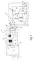
- das Schaltbild des Vorschaltgerätes zum Betrieb mit einer Gasentladungslampe,
- Fig. 2
- das Schaltbild des Vorschaltgerätes zum Betrieb mit zwei Gasentladungslampen und
- Fig. 3
- den Wechselrichter für die Vorschaltgeräte nach den Fig. 1 und 2
- Fig. 1
- the circuit diagram of the ballast for operation with a gas discharge lamp,
- Fig. 2
- the circuit diagram of the ballast for operation with two gas discharge lamps and
- Fig. 3
- the inverter for the ballasts according to FIGS. 1 and 2
In der Serie zu der Primärwicklung 13 ist eine Primärwicklung 21 eines weiteren Transformators 22 geschaltet, der außerdem eine Sekundärwicklung 23 trägt. Der Zweck der Sekundärwicklung 23 wird in Zusammenhang mit Fig. 2 erläutert. Die Primärwicklung 21 ist die eigentliche frequenzbestimmende Induktivität, da sie groß ist gegenüber der Induktivität der Wicklung 13.In series with the primary winding 13, a primary winding 21 of a
Die Serienschaltung aus dem Transformator 12 und dem Transformator 22 enthält schließlich noch einen Kondensator 24, der die Aufgabe hat, einen eventuell vorhandenen Gleichspannungsanteil an dem Ausgang 8 zu unterdrücken. Ansonsten soll der Kondensator 24 möglichst keinen Einfluß auf die Funktion der Schaltung haben.Finally, the series circuit comprising the
An den Kondensator 24 ist die Heizwendel 3, die zwei Anschlüsse 25 und 26 hat, mit ihrem Anschluß 25 angeschaltet. Die andere Heizwendel 24 weist ebenfalls zwei Anschlüsse 27 und 28 auf. Ihr Anschluß 27 führt zu dem Ausgangsanschluß 9.The
Parallel zu der Gasentladungslampe 2 liegt ein frequenzbestimmender Kondensator 29, der mit den Enden 26 und 28 verbunden ist. Der frequenzbestimmende Kondensator 29 bildet zusammen mit der Gesamtinduktivität aus der Primärwicklung 13 und der Primärwicklung 21 einen Serienresonanzkreis, der die Betriebsfrequenz des Wechselrichters 5 festlegt und gleichzeitig für eine Resonanzspannungsüberhöhung an der Gasentladungslampe 2 sorgt. Der Kondensator 24 ist groß gegenüber dem Kondensator 29, so daß er als frequenzbestimmendes Glied in dem Serienresonazkreis praktisch keine Rolle spielt.Parallel to the
Um vor dem Zünden der Gasentladungslampe 2 die beiden Heizwendel 3 und 4 zu heizen, liegt zu dem Kondensator 29 eine Vorheizeinrichtung 31 parallel, die als Zweipol mit zwei Anschlüssen 32 und 33 ausgeführt ist. Die Vorheizeinrichtung 31 enthält einen Brückengleichrichter 34, dessen Wechselspannungseingänge mit den Anschlüssen 33 und 32 verbunden sind, d. h. er ist zu dem frequenzbestimmenden Kondensator 29 und damit auch zu der Gasentladungslampe 2 parallel geschaltet.In order to heat the two
Seine Gleichspannungsausgänge führen zu einer Serienschaltung aus einem ohmschen Widerstand 35 und einem N-Kanal MOS-Fet 36 vom Anreicherungstyp, und zwar ist der ohmsche Widerstand 35 an die Drainelektrode angeschaltet. Die Source-Elektrode führt zu dem Brückengleichrichter 34 zurück.Its DC voltage outputs lead to a series connection of an
Zum Schutz des MOS-Fet liegt zu diesem ein Varistor 37 parallel, der an die Source- und die Drainelektrode des MOS-Feldes angeschlossen ist. Der MOS-Fet 36 wird an seinem Gate von einer Zeitstufe 38 gesteuert. Diese enthält eine Serienschaltung aus einem ohmschen Widerstand 39 sowie einer Z-Diode 41, die zwischen dem Gate und der Source-Elektrode des Feldeffekt-Transistors 36 geschaltet ist, während der Widerstand 39 zu dem heißen Ende des Widerstandes 35 bzw. dem entsprechenden Gleichspannungsausgang des Brückengleichrichters 34 führt. Parallel zu der Z-Diode 41 ist ein bipolarer Transistor 42 vorhanden, dessen Emitter zu der Anode der Z-Diode 41 und dessen Kollektor zu der Basis des Feldeffekt-Transistors 36 bzw. der Kathode der Z-Diode 41 führt. Von der Basis des NPN-Transistors 42 geht eine weitere Z-Diode 43 zu einem zeitbestimmenden Kondensator 44, und zwar ist die Z-Diode 43 mit der Kathode an den Kondensator 44 angeschlossen. Das Laden des zeitbestimmenden Kondensators 44 geschieht mit Hilfe eines ebenfalls zeitbestimmenden Widerstandes 45, der die Kathode der Z-Diode 43 mit dem heißen Ende des Widerstandes 39 verbindet.To protect the MOS-Fet, a
Um bei abgeschalteter Versorgungsspannung den Kondensator 44 zu entladen, damit die Zeitstufe 38 zurückgesetzt werden kann, liegt schließlich zu dem Kondensator 44 ein Entladewiderstand 46 parallel.In order to discharge the
Das insoweit beschriebene Vorschaltgerät 1 arbeitet wie folgt:
Beim Einschalten der Netzspannung an den Stromversorgungseingängen 6 und 7 beginnt der Wechselrichter 5 zu arbeiten und erzeugt an seinem Ausgang 8 gegenüber der Schaltungsmasse 11 eine Wechselspannung, deren Frequenz wegen der Rückkopplung über die Wicklungen 14 und 15 von der Resonanzfrequenz des an dem Ausgang 8 angeschlossenen Serienresonanzkreis festgelegt wird, dessen überwiegend frequenzbestimmende Glieder der Kondensator 29 sowie die Gesamtinduktivität aus den Wicklungen 13 und 21 ist. Dadurch entsteht an den beiden Heizwendeln 3, 4 der Gasentladungslampe 2 eine Wechselspannung, die auch in die Vorheizeinrichtung 31 gelangt, weil sie mit ihren beiden Anschlüssen 32 und 33 zu der Gasentladungslampe 2 parallel liegt.The ballast 1 described so far works as follows:
When the mains voltage is switched on at the
Sobald an den Eingangsanschlüssen des Brückengleichrichters 34 eine Spannung erscheint, wird der MOS-Fet 36 durchgesteuert, womit praktisch der Brückengleichrichter 34 an seinen Ausgangsanschlüssen mit dem Widerstand 35 belastet ist. Folglich liegt zu der Gasentladungslampe 2, elektrisch gesehen, der Widerstand 35 parallel. Die Ausgangsspannung aus dem Wechselrichter 5 führt folglich zu einem Heizstrom durch die Heizwendel 3 und 4. Im einzelnen fließt der Strom, der aus dem Anschluß 8 kommt, durch die Wicklungen 13 und 21, den Kondensator 24, die Heizwendel 3 und in den Brückengleichrichter 34. Da der Brückengleichrichter ausgangsseitig durch den Widerstand 35 überbrückt ist - der MOS-Fet 36 ist durchgesteuert - fließt der Strom über den Brückengleichrichter 34 durch die Heizwendel 4 zu dem Anschluß 9. Gleichzeitig wird hierdurch die Kreisgüte des Serienresonanzkreises verrringert und die Längsspannung an der Gasentladungslampe 2 auf Werte heruntergezogen, die unterhalb der Zündspannung der Gasentladungslampe 2 liegen.As soon as a voltage appears at the input connections of the
Da die Serienschaltung aus dem Widerstand 35 und dem MOS-Fet 36 über einen Brückengleichrichter an dem Kondensator 29 liegt, sind für beide Stromhalbwellen gleiche Verhältnisse vorhanden, d. h. beide Stromhalbwellen tragen zum Aufheizen der beiden Heizwendel 3 und 4 bei.Since the series circuit comprising the
Der erwähnte Schaltzustand des MOS-Fets 36 stellt sich, wie erwähnt, unmittelbar nach dem Auftauchen einer Längsspannung an der Gasentladungslampe 2 ein, weil umgehend das Gate des MOS-Fets 36 über den Widerstand 39 mit einer entsprechenden Vorspannung beaufschlagt wird, deren Größe durch die Z-Diode 41 auf einen geeigneten Wert begrenzt ist. Im vorliegenden gezeichneten Fall gelangt so an das Gate des Feldeffekt-Transistors 36 eine positive Versorgungsspannung mit stabilisierter Größe. Der bipolare NPN-Transistor 42 ist unmittelbar nach dem Einschalten einer Spannung zwischen den beiden Anschlüssen 32 und 33 der Vorheizeinrichtung 31 gesperrt, denn der Kondensator 44 an seiner Basis ist über den Widerstand 46 entladen.The mentioned switching state of the MOS-
Die Versorgungsspannung für das RC-Glied, bestehend aus dem Kondensator 44 und dem Widerstand 45, ist gleich dem Spannungsabfall an dem Drainwiderstand 35 des durchgesteuerten MOS-Fet 36. Der Kondensator 44 lädt sich folglich im Laufe der Zeit auf, bis seine Spannung größer als die Durchlaß-Spannung der Z-Diode 43 zuzüglich der Basisemitterspannung des Transistors 42 wird. Sobald dieser Punkt erreicht ist, wird der Transistor 42 aufgesteuert und hierdurch das Gate des Feldeffekt-Transistors 36 zu seinem Source-Anschluß hin kurzgeschlossen. Der Feldeffekt-Transistor 36 sperrt, d. h. der Widerstand 35 wird von der Gasentladungslampe 2 abgeschaltet. Die wegfallende Belastung des Serienresonanzkreises läßt an dem Kondensator 29 sprunghaft die Spannung ansteigen, die wegen der Resonanzüberhöhung größer ist als die Ausgangsspannung des Wechselrichters 5, gemessen zwischen dem Ausgang 8 und dem Ausgang 9. Der Anstieg der Längsspannung an der Gasentladungslampe 2 führt unmittelbar zu deren Zünden, jedoch nun mit vorgeheizten Heizwendeln 3 und 4, d. h. es erfolgt ein Warmstart.The supply voltage for the RC element, consisting of the
Die einzige Belastung, die in dieser Betriebssituation noch zu dem frequenzbestimmenden Kondensator 29 parallel liegt, ergibt sich aus dem Basis- und dem Kollektrostrom des Transistors 42, der aber gegenüber dem Lampenstrom zu vernachlässigen ist. Er liegt in der Größenordnung von weniger als 1 mA, während der Strom durch die Gasentladungslampe 2 um mehr als den Faktor 1000 größer ist. Die Vorheizeinrichtung 31 kann damit aus elektrischer Sicht vollkommen vernachlässigt werden, sobald die Gasentladungslampe 2 gezündet hat. Der Impedanzwert zwischen den Anschlüssen 32 und 33 ist verschwindend klein verglichen mit dem Innenwiderstand der brennenden Gasentladungslampe 2. Andererseits sorgt die Brennspannung der Gasentladungslampe 2 dafür, daß der Ladezustand des Kondensators 44 erhalten bleibt und somit auch der Transistor 42 durchgesteuert ist, während die Gasentladungslampe 2 brennen soll.The only load which, in this operating situation, is still parallel to the frequency-determining
Sobald die Spannung an den Stromversorgungseingängen 6 und 7 abgeschaltet wird, verschwindet auch die Spannung an der Gasentladungslampe 2 und in der Vorheizeinrichtung 31 kann sich der Kondensator 44 über den Widerstand 46 entladen. Die Entladezeitkonstante liegt zweckmäßigerweise im Bereich der Abkühlzeitkonstanten der Heizwendel 3 und 4. Wird unmittelbar nach Ausschalten erneut eingeschaltet, bleibt die Vorheizeinrichtung 31 inaktiv und die Ausgangsspannung an dem Wechselrichter 5 steigt sofort auf den Zündspannungswert, um die Gasentladungslampe 2 bei noch warmen Heizwendeln 3 und 4 zu zünden. Wenn dagegen umgekehrt die Ausschaltzeit so groß ist, daß die Heizwendel 3, 4 auskühlen, ist auch der zeitbestimmende Kondensator 44 über den Widerstand 46 entladen, womit sich das eingangs erläuterte Spiel wiederholt, sobald die Spannung an die Stromversorgungseingänge 6 und 7 angeschlossen wird.As soon as the voltage at the
Fig. 2 zeigt die Verwendung des neuen Vorschaltgerätes beim Betrieb von zwei Gasentladungslampen 2a und 2b. Soweit in der Schaltung nach Fig. 2 dieselben Bauelement auftauchen wie bei dem Schaltbild nach Fig. 1, werden dieselben Bezugszeichen hierfür verwendet und ihre Funktion nicht erneut beschrieben. Für die Heizwendel der Gasentladungslampe 2a sind dieselben Bezugszeichen wie für die Gasentladungslampe 2 aus Fig. 1 verwendet. Die Gasentladungslampe 2b hat denselben Aufbau, weshalb die Bezugszeichen um den Index b erweitert sind.Fig. 2 shows the use of the new ballast when operating two
In der elektrischen Verbindung zwischen dem Koppelkondensator 24 und dem frequenzbestimmenden Kondensator 29 liegt die Heizwendel 3. Die Heizwendel 4 dagegen ist mit ihrem Ende 24 an die bereits erläuterte Sekundärwicklung 23 angeschlossen, während das andere Ende 28 zu dem Ende 26b der Heizwendel 3b führt. Von hier aus besteht über das Ende 25b eine Verbindung zu der Sekundärwicklung 23; mit anderen Worten, zu der Wicklung 23 liegt die Serienschaltung aus beiden Heizwendeln 4 und 3b parallel. Die Heizwendel 4b hingegen ist so geschaltet wie die Heizwendel 4 nach Fig. 1, d. h. einends liegt sie an dem frequenzbestimmenden Kondensator 29 und andernends an der Anschluß 9.The
Beim Einschalten der Versorgungsspannung für den Wechselrichter 5 verhält sich die Vorheizeinrichtung 31 wie bereits beschrieben und erzeugt einen Heizstrom in der Heizwendel 3 und der Heizwendel 4b, da diese beiden Heizwendel über den Drainwiderstand 35 miteinander verbunden sind. Der hierdurch erzeugte Wechselstrom durch den Transformator 22 erzeugt in dessen Sekundärwicklung 23 ebenfalls einen Wechselstrom, der die beiden in Serie geschalteten Heizwendel 4 und 3b mit Strom beaufschlagt, womit auch diese geheizt werden. Sobald der Kondensator 44 hinreichend aufgeladen ist, schaltet die Vorheizeinrichtung 31 sprunghaft auf den hohem Impedanzwert um. Die sich dadurch verbessernde Kreisgüte und wegfallende Belastung parallel zu dem Kondensator 29 läßt die Spannung an der Serienschaltung der beiden Gasentladungslampen 2a und 2b auf den Zündwert ansteigen und beide Gasentladungslampen 2a und 2b werden gleichzeitig eingeschaltet. Die Vorheizung an den beiden Heizwendeln 4 und 3b bleibt auch im Brennbetrieb erhalten. Die hierbei aufgewandte elektrische Leistung liegt bei ca. 1 Watt und kann deshalb vernachlässigt werden.When the supply voltage for the
Eine mögliche Ausführungsform des Wechselrichters 5 ist in Fig. 3 veranschaulicht. Der Wechselrichter 5 enthält ausgangsseitig zwei zu einer Halbbrücke geschalteten Leisstungstransistoren 51 und 52. Die beiden Leistungstransistoren 51 und 52, in gezeigten Ausführungsbeispiel sind es NPN-Transistoren, sind hintereinander geschaltet und liegen zwischen einer positiven Versorgungsspannung und der Schaltungsmasse 11. Die positive Versorgungsspannung Ub wird in bekannter Weise aus der gleichgerichteten und über einen Kondensator gesiebten Netzspannung erzeugt. Sie liegt in der Größenordnung von 350 V.A possible embodiment of the
Jeder der beiden Transistoren 51 und 52 ist von seinem Kollektor zu seinem Emitter mit Hilfe einer Freilaufdiode 53 bzw. 54 überbrückt.Each of the two
Zum Steuern des Ein- und Ausschaltens der beiden Transistoren 51 und 52 liegt die Sekundärwicklung 14 an der Basisemitterstrecke des Transistors 51 und die Wicklung 15 an der Basisemitterstrecke des Transistors 53.To control the switching on and off of the two
Da diese Schaltung von alleine nicht anschwingt, ist eine Anschwinghilfe vorhanden, die ein von der postiven Versorgungsspannung Ub gegen Masse geschaltetes RC-Glied aus einem Widerstand 55 und einem Kondensator 56 enthält. Zwischen dem Widerstand 55, der die Ladezeit des Kondensators 56 festlegt, befindet sich in Serie geschaltet noch ein Schutzwiderstand 57, der die Aufgabe hat, beim Entladen des Kondensators 56 für eine Strombegrenzung zu sorgen. Die Verbindungsstelle zwischen den beiden Widerständen 55 und 57 liegt über einem Diac 58 an der Basis des Transistors 51.Since this circuit does not start by itself, a start-up aid is present which contains an RC element made up of the
Eine ebenfalls an die Verbindungsstelle zwischen den Widerständen 55 und 57 angeschlossene Diode 59 setzt die Anschwinghilfe still, sobald der Wechselrichter 5 arbeitet.A
Unmittelbar nach dem Einschalten der Versorgungsspannung Ub sind zunächst einmal die beiden Transistoren 51 und 52 gesperrt, weil sie keine positive Basisvorspannung erhalten. Über die Widerstände 55 und 57 kann der Kondensator 56 geladen werden, bis seine Spannung größer ist als die Spannung des Diac 58, der sodann durchbricht und einen positiven Stromimpuls an die Basis des Transistors 51 abgibt.Immediately after switching on the supply voltage U b , the two
Hierdurch kann nun über den vorerwähnten Serienresoanzkreis ein Strom über den Transistor 51 nach Masse fließen. Die dadurch hervorgerufene Spannung in der Wicklung 14 liegt dabei in der Polarität so, daß sie bestrebt ist, den Transistor 51 aufzusteuern, der dadurch in der Sättigung gehalten wird. Dieser Zustand bleibt erhalten, bis infolge der Eisensättigung in der Wicklung 14 keine Spannung mehr induziert wird. Hierdurch wird der Transistor 51 abgeschaltet, und es fließt nun ein abklingender Freilaufstrom über die Freilaufdiode 53. Das Abklingen des Stromes hat die Induktion von Spannungen in beiden Wicklungen 14 und 15 zur Folge, jedoch mit umgekehrter Polarität gegenüber dem vorher betrachteten Fall. Dadurch wird der Transistor 52 aufgesteuert, während der Transistor 51 abgeschaltet bleibt.As a result, a current can now flow to ground via
Dieses Spiel des wechselweisen Einschaltens der Transistoren 51 und 52 setzt sich so lange fort, bis die Versorgungsspannung Ub ausgeschaltet wird.This game of alternately switching on the
Bei jedem Durchsteuern des Transistors 51 wird über die Diode 59 und den Schutzwiderstand 57 der Kondensator 56 entladen. Dadurch wird sichergestellt, daß während der anderen Halbwelle die Zeit nicht ausreicht, um über den Widerstand 55 den Kondensator 56 bis auf die Durchlaß-Spannung des Diac 58 aufzuladen. Sobald der Wechselrichter 5 einmal angeschwungen ist, erreicht der Kondensator 56 nie mehr eine Spannnung, die ausreicht, um den Diac 58 zu zünden.Each
Aus Gründen der Übersichtlichkeit sind die dem Fachmann geläufigen Schutzwiderstände in den Basis- und Emitterzuleitungen der Transistoren 51 und 52 sowie Widerstände und Kondensatoren weggelassen, die lediglich den Zweck haben, die Schaltung zu entstören. Es fehlen auch die Schutzmaßnahmen für den Wechselrichter 5 gegen HF-Schwingungen bei Unterbrechung im Serienresonanzkreis.For reasons of clarity, the protective resistors familiar to the person skilled in the art are omitted in the base and emitter leads of the
Claims (15)
Applications Claiming Priority (2)
| Application Number | Priority Date | Filing Date | Title |
|---|---|---|---|
| DE4119775 | 1991-06-15 | ||
| DE19914119775 DE4119775A1 (en) | 1991-06-15 | 1991-06-15 | CONTROL UNIT WITH CONTROLLED HEATING TIME |
Publications (1)
| Publication Number | Publication Date |
|---|---|
| EP0519220A1 true EP0519220A1 (en) | 1992-12-23 |
Family
ID=6434024
Family Applications (1)
| Application Number | Title | Priority Date | Filing Date |
|---|---|---|---|
| EP92108303A Withdrawn EP0519220A1 (en) | 1991-06-15 | 1992-05-16 | Ballast with controlled heating time |
Country Status (2)
| Country | Link |
|---|---|
| EP (1) | EP0519220A1 (en) |
| DE (1) | DE4119775A1 (en) |
Cited By (5)
| Publication number | Priority date | Publication date | Assignee | Title |
|---|---|---|---|---|
| FR2718598A1 (en) * | 1994-04-06 | 1995-10-13 | Hamm Valery | Device for controlling a fluorescent tube |
| WO1998024277A1 (en) * | 1996-11-24 | 1998-06-04 | Jbp Technologies Ltd. | Method and starter circuits for igniting and operating discharge lamps |
| EP1276355A2 (en) * | 2001-07-10 | 2003-01-15 | Patent-Treuhand-Gesellschaft für elektrische Glühlampen mbH | Circuit arrangement to determine the pre-heating power |
| DE20303594U1 (en) * | 2002-12-23 | 2004-05-06 | Steca Batterieladesysteme und Präzisionselektronik GmbH | Pre-heating circuit for a discharge bulb, especially a low energy discharge bulb, comprises a direct current voltage source for the preheater circuit |
| CN100346674C (en) * | 2002-08-19 | 2007-10-31 | 松下电工株式会社 | Starter for discharging lamp |
Families Citing this family (3)
| Publication number | Priority date | Publication date | Assignee | Title |
|---|---|---|---|---|
| DE4328306A1 (en) * | 1993-08-23 | 1994-03-17 | Spindler Bernhard Dipl Ing | Circuit for HF operation for low presence discharge lamps - has rectifier and inverter and several opto-couplers, with controlled load circuit |
| DE9404469U1 (en) * | 1994-03-16 | 1994-11-10 | Trilux Lenze Gmbh & Co Kg | Multi-lamp ballast for discharge lamps |
| DE29605967U1 (en) * | 1996-03-30 | 1996-06-13 | Trilux Lenze Gmbh & Co Kg | Fluorescent ballast |
Citations (5)
| Publication number | Priority date | Publication date | Assignee | Title |
|---|---|---|---|---|
| US4227118A (en) * | 1977-12-01 | 1980-10-07 | The General Electric Company Limited | Circuits for operating electric discharge lamps |
| DE3401653A1 (en) * | 1983-01-20 | 1984-07-26 | Zumtobel Ag, Dornbirn | Invertor circuit for operating gas-discharge lamps |
| US4647817A (en) * | 1984-11-16 | 1987-03-03 | Patent-Truehand Gesellschaft m.b.H. | Discharge lamp starting circuit particularly for compact fluorescent lamps |
| DE3835533A1 (en) * | 1988-10-19 | 1990-04-26 | Hueco Gmbh | Electronic starting device for starting fluorescent lamps in radio-frequency operation |
| DE3901111A1 (en) * | 1989-01-16 | 1990-07-19 | Patent Treuhand Ges Fuer Elektrische Gluehlampen Mbh | CIRCUIT ARRANGEMENT FOR THE OPERATION OF DISCHARGE LAMPS |
Family Cites Families (4)
| Publication number | Priority date | Publication date | Assignee | Title |
|---|---|---|---|---|
| DE2122411A1 (en) * | 1971-05-06 | 1972-11-30 | Bbc Brown Boveri & Cie | Circuit arrangement for igniting, controlling and operating a gas discharge lamp |
| US4503359A (en) * | 1979-09-12 | 1985-03-05 | Hitachi Lighting, Ltd. | Discharge lamp lighting device |
| EP0078790A3 (en) * | 1981-11-02 | 1983-09-21 | Franz Wittmann | Electronic ignition circuit for gas discharge lamps |
| NL8400923A (en) * | 1984-03-23 | 1985-10-16 | Philips Nv | ELECTRICAL DEVICE FOR IGNITION AND POWERING A GAS AND / OR VAPOR DISCHARGE TUBE. |
-
1991
- 1991-06-15 DE DE19914119775 patent/DE4119775A1/en not_active Ceased
-
1992
- 1992-05-16 EP EP92108303A patent/EP0519220A1/en not_active Withdrawn
Patent Citations (5)
| Publication number | Priority date | Publication date | Assignee | Title |
|---|---|---|---|---|
| US4227118A (en) * | 1977-12-01 | 1980-10-07 | The General Electric Company Limited | Circuits for operating electric discharge lamps |
| DE3401653A1 (en) * | 1983-01-20 | 1984-07-26 | Zumtobel Ag, Dornbirn | Invertor circuit for operating gas-discharge lamps |
| US4647817A (en) * | 1984-11-16 | 1987-03-03 | Patent-Truehand Gesellschaft m.b.H. | Discharge lamp starting circuit particularly for compact fluorescent lamps |
| DE3835533A1 (en) * | 1988-10-19 | 1990-04-26 | Hueco Gmbh | Electronic starting device for starting fluorescent lamps in radio-frequency operation |
| DE3901111A1 (en) * | 1989-01-16 | 1990-07-19 | Patent Treuhand Ges Fuer Elektrische Gluehlampen Mbh | CIRCUIT ARRANGEMENT FOR THE OPERATION OF DISCHARGE LAMPS |
Cited By (8)
| Publication number | Priority date | Publication date | Assignee | Title |
|---|---|---|---|---|
| FR2718598A1 (en) * | 1994-04-06 | 1995-10-13 | Hamm Valery | Device for controlling a fluorescent tube |
| US5604408A (en) * | 1994-04-06 | 1997-02-18 | Hamm; Valery | Control device for a fluorescent tube, having synchronized blocking of auxiliary and primary transistors |
| WO1998024277A1 (en) * | 1996-11-24 | 1998-06-04 | Jbp Technologies Ltd. | Method and starter circuits for igniting and operating discharge lamps |
| EP1276355A2 (en) * | 2001-07-10 | 2003-01-15 | Patent-Treuhand-Gesellschaft für elektrische Glühlampen mbH | Circuit arrangement to determine the pre-heating power |
| EP1276355A3 (en) * | 2001-07-10 | 2003-02-12 | Patent-Treuhand-Gesellschaft für elektrische Glühlampen mbH | Circuit arrangement to determine the pre-heating power |
| US6657403B2 (en) | 2001-07-10 | 2003-12-02 | Patent Treuhand Gesellschaft Fur Elektrische Gluhlampen Mbh | Circuit arrangement for operating a fluorescent lamp |
| CN100346674C (en) * | 2002-08-19 | 2007-10-31 | 松下电工株式会社 | Starter for discharging lamp |
| DE20303594U1 (en) * | 2002-12-23 | 2004-05-06 | Steca Batterieladesysteme und Präzisionselektronik GmbH | Pre-heating circuit for a discharge bulb, especially a low energy discharge bulb, comprises a direct current voltage source for the preheater circuit |
Also Published As
| Publication number | Publication date |
|---|---|
| DE4119775A1 (en) | 1992-12-17 |
Similar Documents
| Publication | Publication Date | Title |
|---|---|---|
| EP0800335B1 (en) | Circuit for operating electric lamps | |
| EP0798952B1 (en) | Circuit arrangement for operating electric lamps and method of operation | |
| EP0185179B1 (en) | Starting circuit for low-pressure discharge lamps | |
| EP0616752B1 (en) | Circuit for operating one or more low-pressure discharge lamps | |
| DE2323011C3 (en) | Circuit arrangement for the ignition and operation of a gas discharge lamp | |
| DE3608615A1 (en) | CIRCUIT ARRANGEMENT FOR OPERATING LOW-PRESSURE DISCHARGE LAMPS | |
| EP0693864B1 (en) | Circuit for operating one or more lour pressure discharge lamps | |
| DE2116950C3 (en) | Circuit arrangement for igniting and operating gas discharge lamps | |
| EP0471332A1 (en) | Circuit assembly for operating a fluorescent lamp | |
| DE2751464A1 (en) | STARTER TO IGNITE A GAS AND / OR VAPOR DISCHARGE LAMP | |
| EP0054301B1 (en) | Lighting circuit for a low-pressure discharge lamp | |
| EP0519220A1 (en) | Ballast with controlled heating time | |
| DE2802218A1 (en) | ELECTRONIC STARTER TO IGNITE A DISCHARGE LAMP | |
| DE4005776C2 (en) | Circuit arrangement for starting and operating a gas discharge lamp | |
| DE4100349C2 (en) | Electronic ballast | |
| DE2360263C3 (en) | Circuit arrangement for igniting a gas and / or vapor discharge lamp | |
| DE3504803A1 (en) | COUNTER-GENERATOR | |
| EP0155729B1 (en) | Circuit device for the ac operation of high-pressure discharge lamps | |
| EP1424880A2 (en) | Device for operating discharge lamps | |
| EP0021508A1 (en) | Firing and operating circuit arrangement for gas and/or vapour discharge lamps | |
| DE2604914C3 (en) | Circuit arrangement for igniting and operating a discharge lamp | |
| EP0682465B1 (en) | Circuit for operating incandescent lamps | |
| EP2140735B1 (en) | Circuit configuration for starting and operating at least one discharge lamp | |
| EP0221972B1 (en) | Protection circuit for an inverter | |
| DE2725532A1 (en) | Fast starter circuit for AC gas discharge lamp - has diode in series with PTC resistor, discharge starter and capacitor all parallel to lamp |
Legal Events
| Date | Code | Title | Description |
|---|---|---|---|
| PUAI | Public reference made under article 153(3) epc to a published international application that has entered the european phase |
Free format text: ORIGINAL CODE: 0009012 |
|
| AK | Designated contracting states |
Kind code of ref document: A1 Designated state(s): AT BE CH DE DK ES FR GB GR IT LI LU NL PT SE |
|
| 17P | Request for examination filed |
Effective date: 19930311 |
|
| STAA | Information on the status of an ep patent application or granted ep patent |
Free format text: STATUS: THE APPLICATION IS DEEMED TO BE WITHDRAWN |
|
| 18D | Application deemed to be withdrawn |
Effective date: 19941201 |