EP0518492A1 - Système de retenue par coussin d'air - Google Patents
Système de retenue par coussin d'air Download PDFInfo
- Publication number
- EP0518492A1 EP0518492A1 EP92304351A EP92304351A EP0518492A1 EP 0518492 A1 EP0518492 A1 EP 0518492A1 EP 92304351 A EP92304351 A EP 92304351A EP 92304351 A EP92304351 A EP 92304351A EP 0518492 A1 EP0518492 A1 EP 0518492A1
- Authority
- EP
- European Patent Office
- Prior art keywords
- air bag
- bag module
- arming
- pin
- plunger
- Prior art date
- Legal status (The legal status is an assumption and is not a legal conclusion. Google has not performed a legal analysis and makes no representation as to the accuracy of the status listed.)
- Granted
Links
Images

Classifications
-
- B—PERFORMING OPERATIONS; TRANSPORTING
- B60—VEHICLES IN GENERAL
- B60R—VEHICLES, VEHICLE FITTINGS, OR VEHICLE PARTS, NOT OTHERWISE PROVIDED FOR
- B60R21/00—Arrangements or fittings on vehicles for protecting or preventing injuries to occupants or pedestrians in case of accidents or other traffic risks
- B60R21/02—Occupant safety arrangements or fittings, e.g. crash pads
- B60R21/16—Inflatable occupant restraints or confinements designed to inflate upon impact or impending impact, e.g. air bags
- B60R21/20—Arrangements for storing inflatable members in their non-use or deflated condition; Arrangement or mounting of air bag modules or components
- B60R21/205—Arrangements for storing inflatable members in their non-use or deflated condition; Arrangement or mounting of air bag modules or components in dashboards
-
- B—PERFORMING OPERATIONS; TRANSPORTING
- B60—VEHICLES IN GENERAL
- B60R—VEHICLES, VEHICLE FITTINGS, OR VEHICLE PARTS, NOT OTHERWISE PROVIDED FOR
- B60R21/00—Arrangements or fittings on vehicles for protecting or preventing injuries to occupants or pedestrians in case of accidents or other traffic risks
- B60R21/02—Occupant safety arrangements or fittings, e.g. crash pads
- B60R21/16—Inflatable occupant restraints or confinements designed to inflate upon impact or impending impact, e.g. air bags
- B60R21/33—Arrangements for non-electric triggering of inflation
Definitions
- the present invention relates to air bag restraint systems for motor vehicles and in particular to the means for mounting an air bag module behind the fascia of a vehicle, but may also be applied to systems in which an air bag module is mounted in another location within the vehicle.
- the air bag module comprises an inflator which includes a pyrotechnic device and a trigger device which in a collision will initiate a fast burn process to rapidly produce large volumes of gases which will inflate the air bag.
- the trigger device of the inflator has a spring loaded plunger which must first be depressed to arm the inflator, before the inflator can be triggered.
- the present invention provides means for mounting the air bag module which will prevent installation of the air bag module without it being armed and removal of the air bag module from the vehicle until the air bag module has been disarmed.
- an air bag restraint system comprises an air bag module having an inflator with an arming plunger which must be depressed to arm the inflator, characterised in that the air bag module is mounted between a pair of side plates of a bracket assembly for pivotal movement between inoperative and operative positions, means for releasably securing the air bag module in its operative position, an arming mechanism comprising a pin mounted with respect to the arming plunger for transverse movement with respect thereto between a disarmed and an armed position, the pin being adapted to engage a contoured end face of the arming plunger to depress the arming plunger as it moves from its disarmed to its armed position, the pin being biased to its disarmed position and an anvil associated with the bracket assembly being provided for engagement of the pin to move it from its disarmed to its armed position as the air bag module is pivoted from its inoperative to its operative position.
- means is associated with the air bag module for preventing access to fixing means for the bracket assembly when the air bag module is in its operative position, thereby preventing removal of the air bag module while it is armed.
- the air bag module will preferably foul the overlying fascia trim panel, so that the latter may not be fitted until the air bag module has been moved to its operative position and the inflator armed.
- an air bag restraint system includes an air bag module 10 of known construction.
- the air bag module 10 is pivotally mounted between a pair of side plates 12 and 13 of a bracket assembly 11, on a pair of studs 14 extending one from either end of the air bag module 10.
- the side plates 12 and 13 of bracket assembly 11 are interconnected by a cross member 15, secured at either end to the side plates 12 and 13 by means of bolts 16.
- Each of the side plates 12 and 13 has a flange formation 17 by which it may be secured to the vehicle body 18 by means of a bolt 19.
- a tubular reaction member 20 is welded at one end to the cross member 15, a bracket 21 being provided adjacent the other end by which it may be secured to the vehicle body. The tubular reaction member 20 ensures that impacts on the vehicle are transmitted to the air bag module 10, to cause triggering thereof if they are of sufficient magnitude.
- a second stud 25 extends from each end of the air bag module 10, at a position spaced from the studs 14.
- the studs 25 extend through arcuate holes 26 in the side plates 12 and 13 and apertures 28 in catch plates 27 pivotally mounted on each of the side plates 12 and 13.
- the apertures 28 define a pair of angularly spaced detents 29 and 30 interconnected by an arcuate portion 31.
- the catch plates 27 are loaded by means of springs 32 so that when the studs 25 are aligned with one of the detents 29 or 30, the catch plates 27 will be biased so that the studs 25 will engage in the detents 29 or 30.
- the catch plates 27 may then be lifted manually against the load applied by spring 32 to disengage the studs 25 from detents 29, 30 so that the air bag module 10 may be pivoted until the studs 25 are aligned with the other detents 30, 29 when the catch plates 27 may be released to lock the air bag module 10 in that position.
- the detents 29 and 30 define respectively an inoperative position in which the air bag module 10 is pivoted downwardly as illustrated in Figure 2, and an operative position in which the air bag module 10 is directed forwardly as illustrated in Figure 3.
- the front of the air bag module 10 will be located in close proximity to a burstable panel on fascia trim panel 33.
- the front of the air bag module 10 moves forwardly beyond the line of the fascia trim panel 33, so that the latter may not be fitted until the air bag module is pivoted to its operative position.
- Cap members 34 are provided on each end of the air bag module 10, the caps 34 being located such that when the air bag module 10 is in its operative position, they will overlie the fixing bolts 19, thus preventing removal of the air bag module 10 and bracket assembly 11 from the vehicle while the air bag module 10 is in its operative position.
- the studs 14 and 25 are provided with nuts which may be tightened to clamp the air bag module 10 when in its operative position.
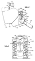
- the air bag module 10 includes an inflator (not shown) having a spring loaded arming plunger 40 which is surrounded by a tubular guard 41 extending from the rear of the air bag module 10.
- An arming mechanism 45 has a housing 46.
- One end of the housing 46 has a cap member 47 which may be secured to the body of the housing 46 by means of a pair of screws 49 to define an aperture 48 corresponding to the external diameter of the tubular guard 41, so that the housing 46 may be clamped around the tubular guard 41.
- a pair of spigot formations 50, 51 engage in diametrically opposed apertures 52 in the tubular guard 41 to provide angular location of the arming mechanism 45 relative to the air bag module 10.
- the housing 46 defines a central axially extending cavity 55 of rectangular section, in which a rectangular shoe 56 is slidably located.
- An arming pin 57 mounted on the shoe 52 extends axially of the cavity 55 and slidably engages through an aperture 58 in spigot formation 51.
- a pair of lugs 60 extend in opposite directions from opposite sides of the shoe 56 through axially extending apertures in the side walls of the cavity 55, into axial bores 61 on either side of the cavity 55.
- the ends of bores 61 adjacent the cap 47 are closed and compression springs 62 act between the closed ends of bores 61 and the lugs 60 to bias the shoe 52 to the end of the cavity 55 remote from the cap 47.
- the front and rear walls defining the chamber 55, at the end remote from cap 47, are partially cut away, to form a keyway 65 parallel to the plane of rotation of the air bag module 10.
- An anvil 66 is secured to the cross member 15 of bracket assembly 11, the anvil 66 being aligned in the same plane of rotation as the keyway 65.
- the base 67 of the shoe 56 remote from end cap 47 is radiused and the opposed edge 68 of the anvil 66 is contoured such that as the air bag module 10 is rotated from its inoperative to its operative position, the shoe 56 will come into engagement with anvil 66 and will be urged axially of the housing 46 towards end cap 47, against the load applied by springs 62.
- the arming plunger 40 has a domed head 43 and the end 69 of arming pin 57 is rounded, such that as the arming pin 57 moves with the shoe 56, it will engage the domed head 43 of plunger 40 to depress plunger 40 and thus arm the inflator.
- the air bag module 10 and bracket assembly 11 of the present invention may typically be installed in a vehicle by first securing the side plate 13 with cross member 15 attached thereto, to the vehicle body by means of bolt 19 and by securing the reaction member 20 to the vehicle by means of bracket 21.
- the air bag module 10 with side plate 12 fitted thereto may then be introduced from the front and side, with the air bag module in its inoperative position, the studs 14 and 25 being located through the appropriate apertures in side plate 13.
- the side plate 12 may then be secured to the vehicle by bolt 19 and to the cross member 15 by bolt 16.
- the catch plates 27 may then be lifted to release studs 25 from the detents 29 and the air bag module 10 rotated to its operative position, where engagement of studs 25 in detents 30 will retain it in that position.
- Finally the nuts on studs 14 and 25 may be tightened to clamp the air bag module 10 in its operative position and the front facia panel may then be fitted.
- the facia panel To remove the air bag module, the facia panel must first be removed and the air bag module 10 rotated back to its inoperative position to permit access to the fixing bolts 19. This will ensure that the inflator of the air bag module 10 is disarmed before removal.
- catch plates are provided at both sides of the air bag module, a single catch plate or other catch means need only be provided at one side. It is however preferred to provide releasable catch means at both sides.
- the construction of the arming mechanism 45 may be varied in respect of; the manner in which the arming mechanism is mounted with respect to the arming plunger 40 of the air bag module; the manner in which the arming pin 57 is guided for movement transverse with respect to the arming plunger 40; and the manner in which the arming pin 57 is resiliently loaded.
- the surface engaged by the anvil 66 is however preferably contoured to provide smooth interengagement and the component defining this surface is located such that the appropriate alignment is maintained.
Landscapes
- Engineering & Computer Science (AREA)
- Mechanical Engineering (AREA)
- Air Bags (AREA)
Applications Claiming Priority (2)
| Application Number | Priority Date | Filing Date | Title |
|---|---|---|---|
| GB919112921A GB9112921D0 (en) | 1991-06-14 | 1991-06-14 | Air bag restraint systems |
| GB9112921 | 1991-06-14 |
Publications (2)
| Publication Number | Publication Date |
|---|---|
| EP0518492A1 true EP0518492A1 (fr) | 1992-12-16 |
| EP0518492B1 EP0518492B1 (fr) | 1995-12-06 |
Family
ID=10696729
Family Applications (1)
| Application Number | Title | Priority Date | Filing Date |
|---|---|---|---|
| EP92304351A Expired - Lifetime EP0518492B1 (fr) | 1991-06-14 | 1992-05-14 | Système de retenue par coussin d'air |
Country Status (5)
| Country | Link |
|---|---|
| US (1) | US5209520A (fr) |
| EP (1) | EP0518492B1 (fr) |
| JP (1) | JPH05185892A (fr) |
| DE (1) | DE69206493T2 (fr) |
| GB (1) | GB9112921D0 (fr) |
Cited By (2)
| Publication number | Priority date | Publication date | Assignee | Title |
|---|---|---|---|---|
| FR2925433A1 (fr) * | 2007-12-20 | 2009-06-26 | Faurecia Interieur Ind Snc | Dispositif de support d'un boitier pour coussin gonfable de securite et vehicule automobile associe |
| US8454052B1 (en) * | 2012-01-17 | 2013-06-04 | Autoliv Asp, Inc. | Air bag inflation in high temperature conditions |
Citations (2)
| Publication number | Priority date | Publication date | Assignee | Title |
|---|---|---|---|---|
| FR2374188A1 (fr) * | 1976-12-17 | 1978-07-13 | Allied Chem | Dispositif a sac gonflable autonome |
| EP0367415A2 (fr) * | 1988-11-01 | 1990-05-09 | Jaguar Cars Limited | Système de retenue par sac d'air |
Family Cites Families (4)
| Publication number | Priority date | Publication date | Assignee | Title |
|---|---|---|---|---|
| JPH07115624B2 (ja) * | 1987-03-25 | 1995-12-13 | 本田技研工業株式会社 | 乗物用エアバツグ装置 |
| US5092628A (en) * | 1988-08-23 | 1992-03-03 | Kabushiki Kaisha Tokai-Rika-Denki Seisakusho | Air bag apparatus |
| JPH02303954A (ja) * | 1989-05-17 | 1990-12-17 | Nissan Motor Co Ltd | 自動車用エアバッグモジュール |
| JPH084363Y2 (ja) * | 1989-08-09 | 1996-02-07 | 株式会社東海理化電機製作所 | エアバッグ安全装置 |
-
1991
- 1991-06-14 GB GB919112921A patent/GB9112921D0/en active Pending
-
1992
- 1992-05-14 EP EP92304351A patent/EP0518492B1/fr not_active Expired - Lifetime
- 1992-05-14 DE DE69206493T patent/DE69206493T2/de not_active Expired - Fee Related
- 1992-06-08 US US07/895,356 patent/US5209520A/en not_active Expired - Fee Related
- 1992-06-12 JP JP4153732A patent/JPH05185892A/ja active Pending
Patent Citations (2)
| Publication number | Priority date | Publication date | Assignee | Title |
|---|---|---|---|---|
| FR2374188A1 (fr) * | 1976-12-17 | 1978-07-13 | Allied Chem | Dispositif a sac gonflable autonome |
| EP0367415A2 (fr) * | 1988-11-01 | 1990-05-09 | Jaguar Cars Limited | Système de retenue par sac d'air |
Non-Patent Citations (2)
| Title |
|---|
| PATENT ABSTRACTS OF JAPAN & JP-A-2 303 954 ( NISSAN MOTOR CO LTD ) 17 December 1990 * |
| PATENT ABSTRACTS OF JAPAN vol. 13, no. 25 (M-787)(3373) 20 January 1989 & JP-A-63 235 144 ( HONDA MOTOR CO LTD ) 30 September 1988 * |
Cited By (2)
| Publication number | Priority date | Publication date | Assignee | Title |
|---|---|---|---|---|
| FR2925433A1 (fr) * | 2007-12-20 | 2009-06-26 | Faurecia Interieur Ind Snc | Dispositif de support d'un boitier pour coussin gonfable de securite et vehicule automobile associe |
| US8454052B1 (en) * | 2012-01-17 | 2013-06-04 | Autoliv Asp, Inc. | Air bag inflation in high temperature conditions |
Also Published As
| Publication number | Publication date |
|---|---|
| DE69206493T2 (de) | 1996-06-05 |
| DE69206493D1 (de) | 1996-01-18 |
| EP0518492B1 (fr) | 1995-12-06 |
| JPH05185892A (ja) | 1993-07-27 |
| GB9112921D0 (en) | 1991-08-07 |
| US5209520A (en) | 1993-05-11 |
Similar Documents
| Publication | Publication Date | Title |
|---|---|---|
| EP0565209B1 (fr) | Système de retenue par sac gonflable | |
| US5433472A (en) | Quick-locking device for retention of an inflator in a passenger-side canister | |
| US5145207A (en) | Mounting means for a vehicle passenger side air bag structure | |
| EP1644224B1 (fr) | Ensemble rideau gonflable | |
| EP0264241A2 (fr) | Dispositif de protection contre le vol pour véhicule automobile | |
| JPH04231237A (ja) | 安全ベルト締付装置のための駆動機構 | |
| US5941337A (en) | Anti-theft seat belt | |
| US5127669A (en) | Mounting means for a vehicle passenger side air bag structure | |
| EP0518492B1 (fr) | Système de retenue par coussin d'air | |
| US5069479A (en) | Air bag device | |
| GB2223558A (en) | A security device. | |
| JPH06227354A (ja) | 自動車用エアバッグ装置 | |
| KR100306436B1 (ko) | 자동차의 탑승자 머리 보호구조 | |
| JPS6364851A (ja) | エアバツク | |
| US5478115A (en) | Safety mechanism for mechanical trigger device of gas generator | |
| KR960002430B1 (ko) | 에어백 모듈 | |
| JP3313423B2 (ja) | 自動車のエアバッグ取付構造 | |
| JP3117640B2 (ja) | エアバッグモジュール | |
| JP3419888B2 (ja) | エアバッグ安全装置の解除機構 | |
| KR100559894B1 (ko) | 차량용 커튼 에어백의 전개 충격 흡수장치 | |
| KR0161636B1 (ko) | 시트 벨트 리트렉터의 장착구조 | |
| KR100471758B1 (ko) | 에어백 모듈이 설치된 자동차의 스티어링휠 | |
| JPH09188213A (ja) | 自動車の助手席用エアバッグ装置 | |
| JP2867941B2 (ja) | センサ内蔵型プリテンショナ付きシートベルト巻取装置 | |
| KR0151632B1 (ko) | 충돌시 뒷좌석 탑승객 보호장치 |
Legal Events
| Date | Code | Title | Description |
|---|---|---|---|
| PUAI | Public reference made under article 153(3) epc to a published international application that has entered the european phase |
Free format text: ORIGINAL CODE: 0009012 |
|
| AK | Designated contracting states |
Kind code of ref document: A1 Designated state(s): DE FR GB IT SE |
|
| 17P | Request for examination filed |
Effective date: 19930510 |
|
| 17Q | First examination report despatched |
Effective date: 19940721 |
|
| GRAA | (expected) grant |
Free format text: ORIGINAL CODE: 0009210 |
|
| AK | Designated contracting states |
Kind code of ref document: B1 Designated state(s): DE FR GB IT SE |
|
| PG25 | Lapsed in a contracting state [announced via postgrant information from national office to epo] |
Ref country code: IT Free format text: LAPSE BECAUSE OF FAILURE TO SUBMIT A TRANSLATION OF THE DESCRIPTION OR TO PAY THE FEE WITHIN THE PRE;WARNING: LAPSES OF ITALIAN PATENTS WITH EFFECTIVE DATE BEFORE 2007 MAY HAVE OCCURRED AT ANY TIME BEFORE 2007. THE CORRECT EFFECTIVE DATE MAY BE DIFFERENT FROM THE ONE RECORDED.SCRIBED TIME-LIMIT Effective date: 19951206 |
|
| REF | Corresponds to: |
Ref document number: 69206493 Country of ref document: DE Date of ref document: 19960118 |
|
| ET | Fr: translation filed | ||
| PG25 | Lapsed in a contracting state [announced via postgrant information from national office to epo] |
Ref country code: SE Effective date: 19960306 |
|
| PG25 | Lapsed in a contracting state [announced via postgrant information from national office to epo] |
Ref country code: GB Effective date: 19960514 |
|
| PGFP | Annual fee paid to national office [announced via postgrant information from national office to epo] |
Ref country code: DE Payment date: 19960725 Year of fee payment: 5 |
|
| PLBE | No opposition filed within time limit |
Free format text: ORIGINAL CODE: 0009261 |
|
| STAA | Information on the status of an ep patent application or granted ep patent |
Free format text: STATUS: NO OPPOSITION FILED WITHIN TIME LIMIT |
|
| 26N | No opposition filed | ||
| GBPC | Gb: european patent ceased through non-payment of renewal fee |
Effective date: 19960514 |
|
| PG25 | Lapsed in a contracting state [announced via postgrant information from national office to epo] |
Ref country code: FR Effective date: 19970131 |
|
| PG25 | Lapsed in a contracting state [announced via postgrant information from national office to epo] |
Ref country code: DE Free format text: LAPSE BECAUSE OF NON-PAYMENT OF DUE FEES Effective date: 19980203 |
|
| REG | Reference to a national code |
Ref country code: FR Ref legal event code: ST |