EP0512362A2 - Reinigungseinheit zum Entfernen von Resttoner auf einer lichtempfindlichen Trommel für ein Bilderzeugungsgerät - Google Patents
Reinigungseinheit zum Entfernen von Resttoner auf einer lichtempfindlichen Trommel für ein Bilderzeugungsgerät Download PDFInfo
- Publication number
- EP0512362A2 EP0512362A2 EP92107196A EP92107196A EP0512362A2 EP 0512362 A2 EP0512362 A2 EP 0512362A2 EP 92107196 A EP92107196 A EP 92107196A EP 92107196 A EP92107196 A EP 92107196A EP 0512362 A2 EP0512362 A2 EP 0512362A2
- Authority
- EP
- European Patent Office
- Prior art keywords
- fur brush
- toner
- fur
- photoreceptor drum
- cleaning unit
- Prior art date
- Legal status (The legal status is an assumption and is not a legal conclusion. Google has not performed a legal analysis and makes no representation as to the accuracy of the status listed.)
- Ceased
Links
Images

Classifications
-
- G—PHYSICS
- G03—PHOTOGRAPHY; CINEMATOGRAPHY; ANALOGOUS TECHNIQUES USING WAVES OTHER THAN OPTICAL WAVES; ELECTROGRAPHY; HOLOGRAPHY
- G03G—ELECTROGRAPHY; ELECTROPHOTOGRAPHY; MAGNETOGRAPHY
- G03G21/00—Arrangements not provided for by groups G03G13/00 - G03G19/00, e.g. cleaning, elimination of residual charge
- G03G21/0005—Arrangements not provided for by groups G03G13/00 - G03G19/00, e.g. cleaning, elimination of residual charge for removing solid developer or debris from the electrographic recording medium
- G03G21/0035—Arrangements not provided for by groups G03G13/00 - G03G19/00, e.g. cleaning, elimination of residual charge for removing solid developer or debris from the electrographic recording medium using a brush; Details of cleaning brushes, e.g. fibre density
-
- G—PHYSICS
- G03—PHOTOGRAPHY; CINEMATOGRAPHY; ANALOGOUS TECHNIQUES USING WAVES OTHER THAN OPTICAL WAVES; ELECTROGRAPHY; HOLOGRAPHY
- G03G—ELECTROGRAPHY; ELECTROPHOTOGRAPHY; MAGNETOGRAPHY
- G03G21/00—Arrangements not provided for by groups G03G13/00 - G03G19/00, e.g. cleaning, elimination of residual charge
- G03G21/0005—Arrangements not provided for by groups G03G13/00 - G03G19/00, e.g. cleaning, elimination of residual charge for removing solid developer or debris from the electrographic recording medium
- G03G21/007—Arrangement or disposition of parts of the cleaning unit
- G03G21/0076—Plural or sequential cleaning devices
-
- G—PHYSICS
- G03—PHOTOGRAPHY; CINEMATOGRAPHY; ANALOGOUS TECHNIQUES USING WAVES OTHER THAN OPTICAL WAVES; ELECTROGRAPHY; HOLOGRAPHY
- G03G—ELECTROGRAPHY; ELECTROPHOTOGRAPHY; MAGNETOGRAPHY
- G03G2221/00—Processes not provided for by group G03G2215/00, e.g. cleaning or residual charge elimination
- G03G2221/0005—Cleaning of residual toner
- G03G2221/001—Plural sequential cleaning devices
Definitions
- the present invention relates to a cleaning unit for removing residual toner on a photoreceptor drum surface for use in an image forming apparatus such as an electrophotographic copying machine and printer, and more particularly, to a cleaning unit for removing residual toner by use of a fur brush.
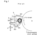
- a cleaning unit for removing residual toner on a surface of a photoreceptor drum is provided.
- the cleaning unit is arranged at a portion corresponding to a downstream side of a transferring process so as to face the surface of the photoreceptor drum.
- a fur brush 4 whose tip is in contact with the surface 1 is arranged in the cleaning unit.
- a recovering roller 5 is provided so that the tip of the fur brush is in contact therewith.
- a blade 301 whose one end is in contact with the surface 1 is arranged in order to remove toner which cannot be removed by the fur brush 4.
- a toner tray 303 for storing removed toner and a screw roller 304 for returning the toner gathered in the toner tray 303 to a toner hopper are arranged at a position below the recovering roller 5.
- One end of the toner tray 303 is arranged to adjoin the surface 1 so that the removed toner does not spill out of the tray 303.
- a blade 302 for removing toner adhering to the roller 5 is arranged so as to be in contact therewith.
- potential applying means 6 is connected for separating residual toner from the surface 1 by electrically attracting it.
- a part of toner which has not been transferred remains on the surface 1 where toner has been transferred onto a copy sheet by the transferring process 2.
- the surface 1 to which the residual toner adheres rotates to the fur brush 4. Since the fur brush 4 rotates and is provided with a potential of a pole reverse to that of the toner by the potential applying means 6, the residual toner adheres to the brush 4 because of frictional force and electrical attraction.
- the toner adhering to the fur brush 4 is conveyed to the recovering roller 5.
- the toner adhering to the fur brush 4 is attracted by the recovering roller 5 and adheres thereto, since the recovering roller 5 is provided with a potential higher than that of the fur brush 4.
- the toner adhering to the recovering roller 5 is rubbed off by the blade 302 which is in contact with the roller 5, and is dropped onto the toner tray 303.
- the number of rotation of the fur brush 4 be approximately 200rpm. Because of the rotation of the fur brush 4, the residual toner scatters.
- the blade 301 arranged in the downstream side of the fur brush 4 also prevents the scattering of toner.
- the toner adhering to the edge of the blade 301 re-adheres to the surface 1, whereby mal-cleaning occurs in a copying operation for a first copy sheet.
- the adhesive power of granular and spherical toner to the surface 1 is so strong that cleaning cannot effectively be performed by a conventional cleaning unit which employs a fur brush or a blade.
- An object of the present invention is to provide a cleaning unit where mal-cleaning does not occur, where a blade for preventing the scattering of toner is unnecessary and where cleaning of granular and spherical toner is effectively performed.
- Another object of the present invention is to provide a cleaning unit where both positively and negatively charged toner can be removed.
- a cleaning unit of the present invention is provided with a plurality of rotatable fur brushes which are arranged so as to adjoin in a downstream direction of a transferring process on a surface of a photoreceptor drum and whose tips are in contact with said surface for removing residual toner on said surface, a recovering roller which rotates in order to remove toner adhering to said fur brushes and which is arranged so as to be in contact with the tip of each of said fur brushes, and potential applying means for applying potential to said fur brushes and said recovering roller, wherein a fur brush arranged at the downmost stream side rotates continuously or intermittently at a lower speed compared to another fur brush arranged in the upstream side thereof.
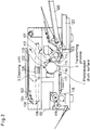
- Fig. 2 is a schematic cross-sectional view of an electrophotographic copying machine including an embodiment of a cleaning unit of the present invention.
- An original glass plate 102 on which an original to be copied is placed is provided on the upper surface of a casing 101 of the body of the copying machine.
- the inside of the casing 101 is divided into an upper and a lower portions.
- an exposure lamp 103 and a mirror 104 which can move as a pair from the downstream end to the upstream end, a pair of movable mirrors 106 for causing a light beams irradiated onto the original to enter a lens 105 arranged below the center of the original glass plate 102, and a fixed mirror 107 for causing the light beams having passed through the lens 105 to expose a surface 1 of a photoreceptor drum are arranged.
- a photoreceptor drum 110 having the photosensing surface 1 is arranged in the center of the lower portion of the casing 101.
- a charging electrode 112 for primary charging is arranged to adjoin the upstream side of an image-formed point of the surface 1.
- a developer unit 113 for causing toner to adhere to the surface 1 is arranged in the downstream side of the charging electrode 112.
- a paper feed roller 114 for feeding a copy sheet is arranged in the downstream side of the developer unit 113.
- a transferring electrode 115 for transferring toner on the surface 1 onto a copy sheet (a transferring process 2) is arranged.
- a separating electrode 116 for separating a copy sheet from the surface 1 is arranged to adjoin the transferring electrode 115.
- a cleaning unit 3 is provided for removing residual toner on the surface 1 after copying.
- a paper conveying belt 117 is provided for conveying a copy sheet onto which toner has been transferred to the fixing side.
- a fixing unit 118 is arranged in the paper discharging side of the belt 117.
- a discharging roller 119 is arranged in the paper discharging side of the fixing unit 118.
- a plurality of paper feed cassettes 120 in which copy sheets of different sizes are set is attached.
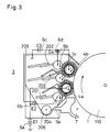
- Fig. 3 is a schematic cross-sectional view of the inside of the cleaning unit 3.
- the cleaning unit 3, which is arranged to adjoin the surface 1, is covered with a case 205 so that the toner recovered from the surface 1 does not scatter.
- a discharger 7 for decreasing the charge of residual toner by AC corona charging is arranged at the uppermost stream side of the cleaning unit 3.
- a fur brush 4a is arranged so that its tip is in contact with the surface 1.
- a fur brush 4b is arranged in a manner similar to the fur brush 4a.
- a recovering roller 5a is provided to the fur brush 4a arranged in the upstream side so as to be in contact with the brush 4a, while a recovering roller 5b is provided to the fur brush 4b arranged in the downstream side so as to be in contact with the brush 4b.
- a recovering roller 5c is arranged so as to be in contact with both of the brushes 4a and 4b.
- Blades 201, 202 and 203 are in contact with the three rollers 5a, 5b and 5c, respectively, in order to remove toner adhering to the rollers 5a, 5b and 5c.
- a toner tray 206 is provided below the case 205 and a screw roller 204 for discharging gathered toner is arranged.
- the exposure lamp 103 irradiates a light beam onto the original while moving from the downstream side to the upstream side of the original glass plate 102.
- the light beam reflected by the original is vertically reflected by the mirror 104.
- it is further reflected by the pair of movable mirrors 106 to enter the lens 105.
- the light beam having entered the lens 105 is reflected in a direction toward the surface 1 which is arranged diagonally to the lower side by the mirror 107 fixed in the side, of the lens 105, opposite to the mirror 106, and is formed into an image on the surface 1 of the photoreceptor drum 110.
- the photoreceptor drum 110 having the surface 1 is rotated. A portion, of the surface 1, which have come to the position of the charging electrode 112 is positively charged by the charging electrode 112. Then, a condition is obtained where a positive charge is accumulated on the external surface of the surface 1 which has been charged and where a negative charge is accumulated on the internal surface of the surface 1.
- a light beam irradiated onto a white portion of the original is reflected to irradiate the surface 1; however, a light beam irradiated onto a black portion is hardly reflected so that the portion, on the surface 1, corresponding to the black portion is not irradiated.
- the positive charge on the external surface is neutralized by the negative charge on the internal surface and disappears, since the electrical resistance of the portion, on the surface 1, which is irradiated by the light beam decreases.
- the positive potential of the portion, which has not been irradiated, of the surface 1 remains intact to form an electrostatic latent image.
- the development unit 113 brings negatively charged toner to the vicinity thereof. Since the latent image and the toner have opposite polarities, respectively, the toner adheres to the portion where the potential remains to form a visible image.
- the photoreceptor drum 110 further rotates under this condition, and a copy sheet conveyed from the paper feed cassette 120 by the paper re-feed roller 114 is put on the surface 1 to which the toner adheres. Then, when the positively charged transferring electrode 115 is brought in the vicinity from the side, of the copy sheet, opposite to the surface 1, the negatively charged toner adheres to the surface of the copy sheet separated from the surface 1. The copy sheet where the toner has been transferred adheres to the surface 1 due to electrostatic force. In order to separate it, the separating electrode 116 arranged to adjoin the downstream side of the transferring electrode 115 is negatively charged. The copy sheet separated by the separating electrode is conveyed to the fixing unit 118 by the paper conveying belt 117. The toner on the conveyed copy sheet is fixed by heat and pressure when the sheet passes between a heat roller and a press roller of the fixing unit 118. The copy sheet where the toner is fixed is discharged by the discharging roller 119.
- the toner on the surface 1 does not completely be removed by the transferring of toner onto the copy sheet. Residual toner exists there. It is necessary to remove the residual toner prior to the next copying operation.
- the cleaning unit 3 is attached for this purpose.
- the surface 1 to which toner adheres passes in the vicinity of the discharger 7 arranged at the uppermost stream position in the cleaning unit 3.
- the discharger 7 performs a function of decreasing the potential of the toner and the charge of the surface of the photoreceptor drum by generating an AC corona between electrodes.
- strongly negatively charged toner is brought into a weakly negatively charged condition
- weakly negatively charged toner is brought into a positively charged condition. Therefore, most of the residual toner on the surface 1 is weakly negatively charged, and a part thereof is weakly positively charged and reaches the fur brush 4a in the up stream side.
- the fur brush 4a is rotating about a rotation axis at a speed of approximately 200rpm in a direction the same as the photoreceptor drum 110.
- the fur brush 4a is provided with a positive potential E1 by the potential applying source 6a.
- the negatively charged residual toner is attracted to the fur brush 4a by frictional force and electrical attraction.
- the toner adhering to the fur brush 4a is brought in contact with the brush and rotates, and is attached to the recovering roller 5a which is provided with a potential higher (by E2) than that of the fur brush 4a.
- the toner adhering to the recovering roller 5a is rubbed off by the edge of the blade 201 arranged to adjoin the roller 5a.
- the weakly positively charged toner remaining on the surface 1 is attracted to the fur brush 4b arranged in the downstream side when the toner is brought to the fur brush 4b, since the brush is provided with a negative potential -E3.
- the fur brush 4b may rotate at a very low speed of approximately 15rpm since the amount of the positively charged toner is only a little. Because of this low speed rotation of the brush, toner does not scatter, and the scattering of toner caused by the fur brush 4a arranged in the upstream side is also prevented.
- the toner adhering to the fur brush 4b adheres to the recovering roller 5b which is provided with a negative potential larger (by -E4) than that of the fur brush 4b, and is separated therefrom by the edge of the blade 202.
- the removing roller 5c is provided with a potential mediating between those of the fur brushes 4a and 4b.
- the roller 5c is provided with a potential of -100.
- the toner removed as described above is rubbed off to a toner tray provided below the case 205 of the cleaning unit 3.
- the gathered toner is returned to a toner hopper by the screw roller 204 and re-used.
- the fur brush 4b may be rotated at a speed the same as that at which the fur brush 4a is rotated.
- FIG. 4 Another embodiment of the present invention is shown in Fig. 4.
- Fig. 4 the same portions as those of Fig. 3 are provided with the same reference designations.
- a rectangular wave voltage is applied by a rectangular wave voltage source 90. Therefore, the portion, of the recovering roller 5c, where a positive portion of the rectangular wave voltage is applied attracts the negatively charged toner on a fur brush 5a, while the portion where a negative portion of the rectangular wave voltage is applied attracts the positively charged toner on a fur brush 5b.
- the positively charged toner and negatively charged toner attracted to the recovering roller 5c as described above is rubbed off by a blade 203 as the recovering roller 5c rotates.
- a sine wave voltage may be applied to the recovering roller 5c instead of the rectangular wave voltage.
- toner is more excellently attracted when a rectangular wave voltage is applied, since the portion where the voltage is changed between positive and negative is steeper in the rectangular wave voltage.
Landscapes
- Physics & Mathematics (AREA)
- General Physics & Mathematics (AREA)
- Cleaning In Electrography (AREA)
Applications Claiming Priority (4)
| Application Number | Priority Date | Filing Date | Title |
|---|---|---|---|
| JP130350/91 | 1991-05-02 | ||
| JP13035091A JPH04330482A (ja) | 1991-05-02 | 1991-05-02 | クリ−ニング装置 |
| JP10762591A JPH04335695A (ja) | 1991-05-13 | 1991-05-13 | クリーニング装置 |
| JP107625/91 | 1991-05-13 |
Publications (2)
| Publication Number | Publication Date |
|---|---|
| EP0512362A2 true EP0512362A2 (de) | 1992-11-11 |
| EP0512362A3 EP0512362A3 (en) | 1993-05-26 |
Family
ID=26447644
Family Applications (1)
| Application Number | Title | Priority Date | Filing Date |
|---|---|---|---|
| EP19920107196 Ceased EP0512362A3 (en) | 1991-05-02 | 1992-04-28 | Cleaning unit for removing residual toner on photoreceptor drum for use in image forming apparatus |
Country Status (2)
| Country | Link |
|---|---|
| US (1) | US5233398A (de) |
| EP (1) | EP0512362A3 (de) |
Cited By (6)
| Publication number | Priority date | Publication date | Assignee | Title |
|---|---|---|---|---|
| EP0784248A1 (de) | 1996-01-08 | 1997-07-16 | Xeikon Nv | Elektrostatographische Tonerbild-Herstellungsstation |
| EP0798610A1 (de) * | 1996-03-27 | 1997-10-01 | Xerox Corporation | Bürstenvorspannung für Doppelbürstenreiniger ohne Vorreinigungskorana für triboelektrisch-negativen Toner |
| EP0684532B1 (de) * | 1994-05-23 | 1999-02-17 | Sharp Kabushiki Kaisha | Reinigungsvorrichtung für ein Bilderzeugungsgerät |
| EP1128233A3 (de) * | 2000-02-24 | 2002-07-31 | Xeikon Nv | Reinigungsvorrichtung |
| EP1845423A1 (de) * | 2006-04-13 | 2007-10-17 | Canon Kabushiki Kaisha | Reinigungseinrichtung und Bilderzeugungsvorrichtung |
| CN110412844A (zh) * | 2018-04-27 | 2019-11-05 | 柯尼卡美能达株式会社 | 显影装置以及图像形成装置 |
Families Citing this family (20)
| Publication number | Priority date | Publication date | Assignee | Title |
|---|---|---|---|---|
| US5663788A (en) * | 1992-04-02 | 1997-09-02 | Ricoh Company, Ltd. | Efficiently removable developing toner in an electrostatic image forming apparatus |
| DE4409188B4 (de) * | 1993-03-18 | 2006-08-17 | Ricoh Printing Systems, Ltd. | Vorrichtung zur Beseitigung von Resttoner von einem Ladungsbildträger einer elektrofotografischen Aufzeichnungsvorrichtung |
| JP2954812B2 (ja) * | 1993-06-14 | 1999-09-27 | 日立工機株式会社 | バイアスクリーニング装置およびそれを用いた静電記録装置ならびにそれらの運転方法 |
| US5771424A (en) * | 1993-10-22 | 1998-06-23 | Xerox Corporation | Preconditioning of photoreceptor and cleaner brush |
| US5438397A (en) * | 1994-03-24 | 1995-08-01 | Kabushiki Kaisha Toshiba | Image forming apparatus |
| US5600425A (en) * | 1995-12-18 | 1997-02-04 | Xerox Corporation | Cleaner system with central augering |
| US6987944B2 (en) * | 2001-03-28 | 2006-01-17 | Ricoh Company, Ltd. | Cleaning device and image forming apparatus using the cleaning device |
| JP2004109631A (ja) * | 2002-09-19 | 2004-04-08 | Ricoh Co Ltd | 画像形成装置及びプロセスカートリッジ |
| US6775512B2 (en) * | 2002-09-23 | 2004-08-10 | Xerox Corporation | Dual electrostatic brush cleaner bias switching for multiple pass cleaning of high density toner inputs |
| JP4458909B2 (ja) * | 2004-04-20 | 2010-04-28 | キヤノン株式会社 | 画像形成装置 |
| US7860429B2 (en) * | 2005-09-09 | 2010-12-28 | Fuji Xerox Co., Ltd. | Cleaning device and image forming apparatus using the same |
| JP2007078937A (ja) * | 2005-09-13 | 2007-03-29 | Canon Inc | 画像形成装置 |
| US7539431B2 (en) * | 2006-06-29 | 2009-05-26 | Kabushiki Kaisha Toshiba | Image forming apparatus and techniques for collecting toner |
| JP4096987B2 (ja) * | 2006-10-31 | 2008-06-04 | 富士ゼロックス株式会社 | 清掃装置、像保持体ユニットおよび画像形成装置 |
| JP5412747B2 (ja) * | 2008-05-01 | 2014-02-12 | コニカミノルタ株式会社 | クリーニング装置及び画像形成装置 |
| JP2010014943A (ja) * | 2008-07-03 | 2010-01-21 | Ricoh Co Ltd | クリーニング装置、画像形成装置、プロセスカートリッジ |
| JP4930496B2 (ja) * | 2008-12-08 | 2012-05-16 | コニカミノルタビジネステクノロジーズ株式会社 | クリーニング装置およびそれを備えた画像形成装置 |
| JP5834962B2 (ja) * | 2012-01-27 | 2015-12-24 | コニカミノルタ株式会社 | 画像形成装置 |
| JP5754422B2 (ja) * | 2012-07-20 | 2015-07-29 | コニカミノルタ株式会社 | クリーニング装置 |
| JP6079290B2 (ja) * | 2013-02-15 | 2017-02-15 | 株式会社リコー | クリーニング装置、プロセスカートリッジおよび画像形成装置 |
Family Cites Families (10)
| Publication number | Priority date | Publication date | Assignee | Title |
|---|---|---|---|---|
| JPS5730869A (en) * | 1980-07-31 | 1982-02-19 | Fuji Xerox Co Ltd | Cleaning device for electrophotographic copier |
| JPS63141087A (ja) * | 1986-12-03 | 1988-06-13 | Ricoh Co Ltd | 電子写真記録装置のクリ−ニング方法 |
| US4819026A (en) * | 1987-12-21 | 1989-04-04 | Xerox Corporation | Cleaning apparatus for a charge retentive surface |
| JPH01167871A (ja) * | 1987-12-24 | 1989-07-03 | Konica Corp | 感光体クリーニング装置 |
| JPH01170976A (ja) * | 1987-12-25 | 1989-07-06 | Matsushita Electric Ind Co Ltd | 多色画像記録装置のクリーニング装置 |
| JPH01219881A (ja) * | 1988-02-29 | 1989-09-01 | Alps Electric Co Ltd | クリーニング方法及び装置 |
| JPH01295289A (ja) * | 1988-05-24 | 1989-11-28 | Ricoh Co Ltd | 電子写真装置のクリーニング装置 |
| US4878093A (en) * | 1988-10-03 | 1989-10-31 | Xerox Corporation | Dual roll cleaning apparatus for charge retentive surface |
| US4999679A (en) * | 1989-12-04 | 1991-03-12 | Xerox Corporation | Cleaning apparatus with housing and brush biased to the same magnitude and polarity |
| US4989047A (en) * | 1989-12-11 | 1991-01-29 | Xerox Corporation | Cleaning apparatus for the reduction of agglomeration-caused spotting |
-
1992
- 1992-04-28 US US07/875,016 patent/US5233398A/en not_active Expired - Fee Related
- 1992-04-28 EP EP19920107196 patent/EP0512362A3/en not_active Ceased
Cited By (7)
| Publication number | Priority date | Publication date | Assignee | Title |
|---|---|---|---|---|
| EP0684532B1 (de) * | 1994-05-23 | 1999-02-17 | Sharp Kabushiki Kaisha | Reinigungsvorrichtung für ein Bilderzeugungsgerät |
| EP0784248A1 (de) | 1996-01-08 | 1997-07-16 | Xeikon Nv | Elektrostatographische Tonerbild-Herstellungsstation |
| EP0798610A1 (de) * | 1996-03-27 | 1997-10-01 | Xerox Corporation | Bürstenvorspannung für Doppelbürstenreiniger ohne Vorreinigungskorana für triboelektrisch-negativen Toner |
| EP1128233A3 (de) * | 2000-02-24 | 2002-07-31 | Xeikon Nv | Reinigungsvorrichtung |
| EP1845423A1 (de) * | 2006-04-13 | 2007-10-17 | Canon Kabushiki Kaisha | Reinigungseinrichtung und Bilderzeugungsvorrichtung |
| US7668478B2 (en) | 2006-04-13 | 2010-02-23 | Canon Kabushiki Kaisha | Image forming apparatus including two toner cleaning members |
| CN110412844A (zh) * | 2018-04-27 | 2019-11-05 | 柯尼卡美能达株式会社 | 显影装置以及图像形成装置 |
Also Published As
| Publication number | Publication date |
|---|---|
| EP0512362A3 (en) | 1993-05-26 |
| US5233398A (en) | 1993-08-03 |
Similar Documents
| Publication | Publication Date | Title |
|---|---|---|
| US5233398A (en) | Cleaning unit for removing residual toner on photoreceptor drum for use in image forming apparatus | |
| JPS58215678A (ja) | 画像形成装置 | |
| EP0020768B1 (de) | Elektrophotographische kopiermaschine | |
| JPH04335695A (ja) | クリーニング装置 | |
| JPH07210053A (ja) | 電子写真装置のクリーニング装置 | |
| JPS6235109B2 (de) | ||
| JPS59133579A (ja) | シ−ト分離装置 | |
| JP3651827B2 (ja) | 接触帯電式画像形成装置 | |
| JP3565345B2 (ja) | 画像形成装置 | |
| US4851879A (en) | Transfer device in electrophotographic copying machine | |
| JPH01269969A (ja) | 画像形成装置 | |
| JP3843690B2 (ja) | 画像形成装置 | |
| JP3310069B2 (ja) | 画像形成装置 | |
| JPS62111275A (ja) | クリ−ニング装置 | |
| JPH09330002A (ja) | クリーニング装置 | |
| JP2663299B2 (ja) | 転写装置 | |
| JP2025075586A (ja) | 静電捕集装置、画像形成装置、及び、清掃装置 | |
| JPH05107990A (ja) | クリーニング装置 | |
| JPH0677169B2 (ja) | 画像形成装置 | |
| JPH06348143A (ja) | 転写紙の静電分離装置 | |
| JPH07121081A (ja) | 画像形成装置 | |
| JP2586898B2 (ja) | 画像形成装置 | |
| JPH0544675B2 (de) | ||
| JPH04343382A (ja) | 画像形成装置 | |
| JPS59187378A (ja) | 磁気ブラシクリ−ニング装置 |
Legal Events
| Date | Code | Title | Description |
|---|---|---|---|
| PUAI | Public reference made under article 153(3) epc to a published international application that has entered the european phase |
Free format text: ORIGINAL CODE: 0009012 |
|
| AK | Designated contracting states |
Kind code of ref document: A2 Designated state(s): DE FR GB IT NL |
|
| PUAL | Search report despatched |
Free format text: ORIGINAL CODE: 0009013 |
|
| AK | Designated contracting states |
Kind code of ref document: A3 Designated state(s): DE FR GB IT NL |
|
| 17P | Request for examination filed |
Effective date: 19931115 |
|
| 17Q | First examination report despatched |
Effective date: 19950206 |
|
| GRAG | Despatch of communication of intention to grant |
Free format text: ORIGINAL CODE: EPIDOS AGRA |
|
| STAA | Information on the status of an ep patent application or granted ep patent |
Free format text: STATUS: THE APPLICATION HAS BEEN REFUSED |
|
| 18R | Application refused |
Effective date: 19960624 |