EP0511939B1 - Dispositif pneumatique d'insertion des fils de trame et machine à tisser avec ce dispositif - Google Patents
Dispositif pneumatique d'insertion des fils de trame et machine à tisser avec ce dispositif Download PDFInfo
- Publication number
- EP0511939B1 EP0511939B1 EP92810247A EP92810247A EP0511939B1 EP 0511939 B1 EP0511939 B1 EP 0511939B1 EP 92810247 A EP92810247 A EP 92810247A EP 92810247 A EP92810247 A EP 92810247A EP 0511939 B1 EP0511939 B1 EP 0511939B1
- Authority
- EP
- European Patent Office
- Prior art keywords
- yarn
- weft
- thread
- gripping
- nozzle
- Prior art date
- Legal status (The legal status is an assumption and is not a legal conclusion. Google has not performed a legal analysis and makes no representation as to the accuracy of the status listed.)
- Expired - Lifetime
Links
- 238000003780 insertion Methods 0.000 title claims description 29
- 230000037431 insertion Effects 0.000 title claims description 29
- 238000009941 weaving Methods 0.000 title description 6
- 235000014676 Phragmites communis Nutrition 0.000 claims description 22
- 238000007664 blowing Methods 0.000 claims description 22
- 238000010009 beating Methods 0.000 claims 1
- 239000004744 fabric Substances 0.000 description 10
- 239000012528 membrane Substances 0.000 description 5
- 239000002699 waste material Substances 0.000 description 3
- 230000015572 biosynthetic process Effects 0.000 description 1
- 230000001419 dependent effect Effects 0.000 description 1
- 238000011161 development Methods 0.000 description 1
- 230000018109 developmental process Effects 0.000 description 1
- 230000009191 jumping Effects 0.000 description 1
- 239000002184 metal Substances 0.000 description 1
- 230000001105 regulatory effect Effects 0.000 description 1
Images

Classifications
-
- D—TEXTILES; PAPER
- D03—WEAVING
- D03D—WOVEN FABRICS; METHODS OF WEAVING; LOOMS
- D03D47/00—Looms in which bulk supply of weft does not pass through shed, e.g. shuttleless looms, gripper shuttle looms, dummy shuttle looms
- D03D47/34—Handling the weft between bulk storage and weft-inserting means
- D03D47/38—Weft pattern mechanisms
-
- D—TEXTILES; PAPER
- D03—WEAVING
- D03D—WOVEN FABRICS; METHODS OF WEAVING; LOOMS
- D03D47/00—Looms in which bulk supply of weft does not pass through shed, e.g. shuttleless looms, gripper shuttle looms, dummy shuttle looms
- D03D47/28—Looms in which bulk supply of weft does not pass through shed, e.g. shuttleless looms, gripper shuttle looms, dummy shuttle looms wherein the weft itself is projected into the shed
- D03D47/30—Looms in which bulk supply of weft does not pass through shed, e.g. shuttleless looms, gripper shuttle looms, dummy shuttle looms wherein the weft itself is projected into the shed by gas jet
- D03D47/3066—Control or handling of the weft at or after arrival
- D03D47/308—Stretching or holding the weft
-
- D—TEXTILES; PAPER
- D03—WEAVING
- D03D—WOVEN FABRICS; METHODS OF WEAVING; LOOMS
- D03D47/00—Looms in which bulk supply of weft does not pass through shed, e.g. shuttleless looms, gripper shuttle looms, dummy shuttle looms
- D03D47/12—Looms in which bulk supply of weft does not pass through shed, e.g. shuttleless looms, gripper shuttle looms, dummy shuttle looms wherein single picks of weft thread are inserted, i.e. with shedding between each pick
- D03D47/125—Weft holding devices
Definitions
- the present invention relates to a device for inserting a weft into the shed of a loom, according to the preamble of claim 1, and a weaving machine, in particular an air jet loom with a Profilriet weft insertion channel, with a thread stop arranged on the weft insertion side for braking the weft after insertion of a preselected one Length of weft thread in the shed and a thread holding device fastened in the area of the shed exit side together with the reed on the sley to take over the end of the weft after completion of the weft insertion.
- a weaving machine in particular an air jet loom with a Profilet weft insertion channel, with a thread stop arranged on the weft insertion side for braking the weft after insertion of a preselected one Length of weft thread in the shed and a thread holding device fastened in the area of the shed exit side together with the reed on the sley to take over the end of the we
- CH 651 861 describes a thread holding device which, on the shed outlet side, has a blow nozzle attached to the sley, acting transversely to the thread running direction, deflecting the weft thread end, and directed into a mixing tube, with which the weft thread reaches subsequent stops and change of subject is kept tense. This avoids jumping back into the shed.
- the disadvantages of these blowing and / or suction nozzles - also known as draw or tensioning nozzles - are in particular the high air consumption and the relatively high waste of yarn.
- the reason for the high air consumption is the relatively long holding time, i.e. the long blowing or suction time to maintain the air flow until the weft thread is woven in and can no longer jump back into the shed.
- the relatively large weft yarn waste arises from the need to exert a sufficiently large tensile force on the weft thread by means of the compressed or suction air flow, which is largely determined by the yarn surface exposed to the air flow.
- the smoother e.g. the yarn surface or the thinner a yarn, the larger the excess yarn length and / or the level of air pressure must generally be selected.
- DE-A-30.28.126 describes a thread holding device at the outlet end of the shed, with a vacuum tube.
- a slot is provided in the intake manifold.
- the clamping unit of the thread holding device has a clamping jaw on a finger, which is inserted into the slot during clamping and holds the thread in the vacuum tube.
- the thread clamp is used to forcefully hold the thread end at the exit of the shed.
- the device according to the invention has the features of the characterizing part of claim 1.
- the dependent ones Claims relate to particularly advantageous developments of the invention, for example arranging the wedge-shaped thread clamping gap of the thread holding device substantially parallel to the running direction of the weft thread or the formation of the thread clamping gap by at least one stationary and one movable clamping part, with contours of the two clamping parts facing each other together forming the said clamping gap.
- the movable clamping part can be moved by an actuating device from a thread holding position into a thread release position, the edges forming the clamping gap being moved away from one another.
- This actuating device is activated at the latest after the weft thread has been struck by means of the reed on the fabric edge in order to release the weft thread in good time before the weaving shed falls.
- the actuator is e.g. from a housing located on the sley, with a piston movable therein via a membrane by compressed air, one end of which is directed against the movable clamping part.
- an actuator consists of a fixed or movable part, e.g. a cam or a roller, which acts on the movable clamping part during the weft stop movement of the reed by enlarging the thread clamping gap and releasing the weft end.
- a fixed or movable part e.g. a cam or a roller
- the thread clamping device forming the thread clamping gap and the blowing or suction nozzle producing the air jet are arranged to the side of the path of the weft thread, the clamping parts forming the clamping gap preferably being either substantially aligned with the reed abutment plane and the nozzle opening being arranged on the fabric side, or conversely the nozzle opening is essentially also arranged aligned with the reed stop plane and the clamping parts forming the clamping gap are arranged on the fabric side.
- the blowing or suction start, duration and pressure of the nozzle can be regulated automatically during machine operation, depending on the type of thread or weft color sequence. In multi-color weaving machines, this regulation is preferably carried out with the aid of the color selection and color control unit.
- the weft insertion device has on the weft exit side of the shed a thread holding device for taking over and releasing the weft end, which essentially comprises two clamping parts and a nozzle.
- the one clamping part is preferably stationary and the other clamping part is movable and together form a wedge-shaped clamping gap.
- a blowing or suction nozzle sucks or blows the end of the weft end into the nip just as the weft insertion is finished.
- the weft end When blowing or sucking in the weft end into the nip with the compressed air pulse from the blowing nozzle or the suction pulse with the suction nozzle, the weft end automatically jams or wedges as soon as the tensile force in the weft thread, which occurs when braking with the thread stopper in the weft thread on the weft insertion side builds up, becomes effective.
- An actuating device acting on the movable clamping part releases the weft thread end during or after the weft thread is struck in the fabric.
- the weft device enables a substantial reduction in air consumption and yarn waste.
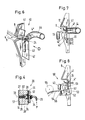
- Fig. 1 shows a fabric web 1, with the warp threads 2, 3 and weft threads 4, 4 '.
- the weft insertion system comprises a weft insertion nozzle 5 for inserting a weft 4 into the shed 6, a reed 7 with profiled reed bars 8 for forming a guide channel 9 for the weft during insertion, as well as for striking the weft thread after it has entered the fabric edge 10, a thread stopper 11 with an actuator 12, for braking a weft thread at the end of the insertion, and a thread holding device 13 according to the invention for holding the weft thread after completion of the weft thread insertion.
- the weft insertion of the weft takes place, for example, with the help of the main nozzle 5 and any additional auxiliary nozzles, not shown here, arranged over the width of the shed.
- the thread holding device 13 is on the sley 7 ', detachable with means not shown and fastened in the longitudinal direction of the reed 7.
- the thread holding device 13 essentially comprises a carrier 14, which has a groove 15 in continuation of the reed channel 9. Furthermore, a stationary clamping part 16, a movable clamping part 17, a blowing nozzle 18 with compressed air connection 19 and an actuating device 20 with compressed air connection 21 are fastened on the carrier 14.
- a lower edge 22 of the stationary clamping part 16 and an upper edge 23 of the movable clamping part 17 together form a wedge-shaped clamping gap 24. The position of the lower edge 22 can be adjusted by moving the clamping part 16 e.g.
- Fig. 1 shows the moment of completion of a weft insertion with the thread stopper 11 in the closed position.
- the blowing nozzle 18 has deflected the weft end 4 ⁇ with a short blowing pulse from the trajectory and blown into the clamping gap 24.
- the weft thread is stretched and tensioned.
- the thread end 4 ⁇ as described above, must be directed through the blowing nozzle 18 into the clamping gap 24 and held there.
- the thread end jams or wedges in the clamping gap 24 without and before and the stretched and stretched thread can spring back into the still open shed.
- the blowing pulse for deflecting the thread end is advantageously timed with the actuation of the thread clamp 11.
- Fig. 2 shows the essential parts of the thread holding device 13 in a side view looking towards the open shed, seen from the weft exit side. With solid lines, the device can be seen in the rear position facing away from the fabric, namely at the moment of deflecting the weft end 4 ⁇ into the thread clamping gap 24 with the blowing nozzle 18.
- the actuating device 20 is in a retracted, inactive position.
- the device is shown in dash-dot lines in the tissue stop position.
- the warp threads 2, 3 were crossed by a shed changing device, not shown, ie heald frames, and the lower clamping part 17 was moved by means of the actuating device 20 moved in the direction of arrow B into the open position 17 'to release the weft end 4'.
- the weft thread 4 ' is now sufficiently secured by crossing the warp threads in its stretched position, so that the weft thread end 4 ⁇ can be released.
- the sley 7 ' with the thread holding device attached to it, now goes back to the starting position facing away from the fabric, while the actuating device 20 in the direction of arrow C. is moved and the resilient or sprung lower clamping part 17 reaches the thread take-over position on the carrier 14 again. The next weft thread can now be pinched.
- FIG. 3 shows part of the thread holding device 13 from FIG. 2 viewed in direction A.
- the mutual position of the clamping parts 16, 17 and the blowing nozzle 18 of the thread holding device 13, which are important for the function of the thread holding device, and on the other hand the actuating device 20 are shown.
- Fig. 4 shows a cross section along line IV - IV of the thread holding device of Fig. 3, wherein essential parts of the actuating device 20 are shown.
- a piston 20 ' With a shaft part 27 of smaller diameter and a head part 28 of larger diameter.
- the piston 20 ' is axially displaceably guided in corresponding bores 29, 30 of the carrier 14.
- the small diameter piston end is directed against the clamping part 17 and the larger diameter piston end is directed against the diaphragm 31.
- the membrane 31 is fastened to the carrier 14 together with the plate 32.
- the compressed air connection 21, the outlet 34 opens into the space delimited by the membrane 31.
- the carrier 14 is provided in the area between the head part 28 of the piston and the membrane with a conical recess 35.
- the actuating device 20 functions as follows:
- the thread end has been gripped by the thread holding device 13 and the weft thread has been struck against the fabric edge by the reed and at the same time upper and lower If the warp threads cross, the membrane 31 is pressurized with compressed air - indicated by the arrow P - via the compressed air connection 21.
- the piston 31 is axially displaced via the diaphragm 31, which moves against the recess 35, and presses with the end of the shaft part against the clamping part 17.
- the clamping gap of the thread holding device 13 opens and expands the thread end 4 ⁇ , as is the case here is shown in broken lines in Fig. 2.
- FIG. 5 schematically illustrates a thread holding device in which the blowing nozzle 18 and the actuating device 20 are each immersed in an alley between two reed bars 8.
- This embodiment of the thread holding device has the advantage that it can be used in a variety of ways regardless of the reed feed width. This solution only requires a suitable reed division, reed bar thickness, and suitable mass of the nozzle 18 and the actuating device 20. 5, the position of the clamping parts 16, 17 is indicated by dash-dotted lines.
- FIGS. 6 and 7 show a modified thread holding device 40, in which the clamping gap 24 forming the clamping parts 41, 42 are substantially in a common plane with the thread guide channel base 9 'and the blowing nozzle 43 blows in the direction facing away from the fabric to the thread end 4 ⁇ to bring into the holding position of the thread holding device 40.
- the upper, stationary clamping part 41 can, for example, be produced as a sheet metal part and shaped to match the reed profile, so that the weft thread end is directed as undisturbed as possible by the air jet from the blowing nozzle 43 into the wedge gap.
- the warp direction behind the nip is preferably also on the sley 7 'attached, curved Pipe 44 arranged. Such a tube is used to remove parts of broken weft threads.
- weft monitors can be arranged which, for example in the case of incorrect weft yarn length or a weft yarn break, emit a signal to the weaving machine control, which, for example, causes the weft yarn length to be changed or the weaving machine to stop in the event of a weft yarn break.
- the actuating device 20 is also shown in dash-dot lines, with the lower clamping part 42 'in the open position.
- FIG. 8 shows a further variant of a thread holding device 50 which is fastened on the sley 7 '.
- the lower clamping part 51 is provided with a rotary bearing 52 which is supported on the reed by a support 53.
- the clamping part is provided with a lever 54.
- This lever extension 54 is deflected by the reed 7 with the cam 55 at the shot stop.
- a spring 56 causes the clamping part 51 to be reset up to the stop 57 of the support 53 as soon as the reed returns to the open shed position.
- the jet of the nozzle is shown in the drawings largely almost parallel to the course of the warp threads, the clamping gap practically parallel to the course of the weft threads and the clamping parts approximately perpendicular to the warp thread family, the invention is of course not restricted to this advantageous arrangement of the parts of the thread holding device.
- the suction or blowing jet of the nozzle but also the clamping gap and clamping parts, inclined to the weft direction and / or to the warp direction.
Claims (10)
- Dispositif pneumatique d'introduction du fil de trame pour métier à tisser, comportant un dispositif de retenue de fil disposé du côté (11) de l'introduction du fil de trame et du côté (13) de sortie de la foule (6) de tissage, caractérisé en ce que le dispositif (13) de retenue de fil présente du côté de la sortie un interstice (24) de pinçage de fil en forme de biseau et une buse de soufflage ou d'aspiration (18) avec laquelle l'extrémité du fil de trame (4) sortant de la foule (6) de tissage est soufflée ou aspirée dans l'interstice (24) de pinçage du fil en forme de biseau et y est ainsi automatiquement immobilisée.
- Dispositif d'introduction du fil de trame selon la revendication 1, caractérisé en ce que l'interstice (24) de pinçage du fil du dispositif (13) de retenue du fil est orienté essentiellement parallèlement aux fils de trame (4).
- Dispositif d'introduction du fil de trame selon la revendication 1 ou 2, caractérisé en ce que l'interstice (24) de pinçage du fil est formé par au moins une pièce de pinçage fixe (16) et au moins une pièce de pinçage mobile (17).
- Dispositif d'introduction du fil de trame selon la revendication 3, caractérisé par un dispositif d'actionnement (20) qui agit sur la pièce de pinçage mobile (17) et amène celle-ci d'une position de retenue du fil jusque dans une position de libération du fil et inversement.
- Dispositif d'introduction de fil de trame selon la revendication 4, caractérisé en ce que l'organe d'actionnement (20') est inséré dans des alésages (29, 30, 35) d'un support (14) fixé sur le battant de tissage (7), tandis qu'une membrane (31) déplaçable par air comprimé agit sur une extrémité (28) de l'organe d'actionnement (20') dont l'autre extrémité (27) actionne la pièce mobile de pinçage (17).
- Dispositif d'introduction du fil de trame selon la revendication 4 ou 5, caractérisé en ce que le dispositif d'actionnement est formé par une pièce (55) qui agit sur la pièce de pinçage mobile (51, 52, 54) pendant le déplacement de battage du battant de tissage 7, de telle sorte que l'interstice de pinçage du fil (24) soit agrandi et libère ainsi l'extrémité (4') du fil de trame.
- Dispositif d'introduction du fil de trame selon l'une des revendications 1 à 6, caractérisé en ce que l'interstice (24) de pinçage du fil de trame du dispositif (13) de retenue du fil et la buse (18) sont disposés latéralement par rapport au canal (9) d'introduction du fil de trame, tandis que les pièces de pinçage (16, 17) formant l'interstice de pinçage (24) sont disposées essentiellement dans l'alignement du plan de battage du battant de tissage, et que l'ouverture de la buse (18) est disposée à distance de ce plan, du côté du tissu.
- Dispositif d'introduction du fil de trame selon l'une des revendications 1 à 6, caractérisé en ce que l'interstice (24) de pinçage du fil du dispositif (13) de retenue du fil et la buse (18) sont disposés latéralement par rapport au canal (9) d'introduction du fil de trame, l'ouverture de la buse (18) étant disposée essentiellement dans l'alignement sur le plan de battage du battant de tissage, et les pièces de pinçage (16, 17) formant l'interstice de pinçage (24) sont disposées à distance de ce plan, du côté du tissu.
- Dispositif d'introduction du fil de trame selon l'une des revendications 1 à 8, caractérisé par des moyens qui régulent automatiquement le moment, la durée et la pression de la buse (18).
- Métier à tisser comportant un dispositif d'introduction du fil de trame selon l'une des revendications 1 à 9.
Applications Claiming Priority (2)
| Application Number | Priority Date | Filing Date | Title |
|---|---|---|---|
| CH1296/91 | 1991-04-30 | ||
| CH129691 | 1991-04-30 |
Publications (2)
| Publication Number | Publication Date |
|---|---|
| EP0511939A1 EP0511939A1 (fr) | 1992-11-04 |
| EP0511939B1 true EP0511939B1 (fr) | 1996-06-05 |
Family
ID=4207114
Family Applications (1)
| Application Number | Title | Priority Date | Filing Date |
|---|---|---|---|
| EP92810247A Expired - Lifetime EP0511939B1 (fr) | 1991-04-30 | 1992-04-02 | Dispositif pneumatique d'insertion des fils de trame et machine à tisser avec ce dispositif |
Country Status (6)
| Country | Link |
|---|---|
| US (1) | US5224521A (fr) |
| EP (1) | EP0511939B1 (fr) |
| JP (1) | JP3423331B2 (fr) |
| KR (1) | KR920019986A (fr) |
| DE (1) | DE59206458D1 (fr) |
| TW (1) | TW224990B (fr) |
Families Citing this family (14)
| Publication number | Priority date | Publication date | Assignee | Title |
|---|---|---|---|---|
| DE4213754C1 (de) * | 1992-04-25 | 1993-12-02 | Dornier Gmbh Lindauer | Einrichtung zum pneumatischen Führen turbulenter Schußfadenenden einer Hilfsgewebeleiste in Luftdüsenwebmaschinen |
| DE19545839C1 (de) * | 1995-12-08 | 1996-08-29 | Dornier Gmbh Lindauer | Verfahren und Webmaschine zur Handhabung eines Schußfadens |
| DE19728013A1 (de) * | 1997-07-01 | 1999-01-07 | Textilma Ag | Vorrichtung zum Strecken und Spannen eines Schussfadens und Webmaschine mit einer solchen Vorrichtung |
| JP3157779B2 (ja) * | 1998-05-18 | 2001-04-16 | 津田駒工業株式会社 | 房耳規制体の駆動装置 |
| JP2000328399A (ja) * | 1999-05-19 | 2000-11-28 | Tsudakoma Corp | 緯糸先端の処理方法および処理装置 |
| DE20107885U1 (de) * | 2001-05-10 | 2001-10-11 | Dornier Gmbh Lindauer | Halteeinrichtung für die Enden von Schussfäden bei einer Luftdüsenwebmaschine |
| DE50300789D1 (de) * | 2002-04-26 | 2005-08-25 | Sultex Ag Rueti | Fang- und Haltevorrichtung für das fangseitige Schussfadenende in einer Webmaschine |
| NL1027372C2 (nl) * | 2004-10-29 | 2006-05-03 | Te Strake Textile B V | Weefinrichting. |
| DE102005022955A1 (de) * | 2005-05-19 | 2006-11-23 | Lindauer Dornier Gmbh | Verfahren und Vorrichtung zum Halten eines nach einem Startvorgang einer Webmaschine, insbesondere Luftdüsenwebmaschine eingetragenen Schussfadens |
| US20080271807A1 (en) * | 2006-09-07 | 2008-11-06 | Sultex Ag | Method and a stretching device for the holding of a weft thread |
| KR100822409B1 (ko) * | 2007-01-10 | 2008-04-17 | 박경희 | 복합재료시트 직조시스템 |
| JP2011122263A (ja) * | 2009-12-10 | 2011-06-23 | Tsudakoma Corp | ゴム補強用織物製織用織機におけるタックイン耳形成装置 |
| CN103161003A (zh) * | 2013-03-27 | 2013-06-19 | 吴江市金平华纺织有限公司 | 一种夹持式异形筘 |
| CN103726199A (zh) * | 2013-12-28 | 2014-04-16 | 吴江市振中纺织品有限公司 | 封闭式异形筘 |
Family Cites Families (6)
| Publication number | Priority date | Publication date | Assignee | Title |
|---|---|---|---|---|
| NL7108526A (fr) * | 1971-06-21 | 1972-12-27 | ||
| FR2478144A1 (fr) * | 1979-08-06 | 1981-09-18 | Leesona Corp | Systeme d'alimentation et d'insertion d'un fil de trame dans un metier a tisser |
| NL8004551A (nl) * | 1980-08-11 | 1982-03-01 | Rueti Te Strake Bv | Werkwijze voor het inbrengen en strekken van een afgemeten inslagdraadstuk in het weefvak van een spoelloze weefmachine. |
| WO1983002466A1 (fr) * | 1982-01-16 | 1983-07-21 | Griffith, John, Dalton | Dispositif de retenue de fil |
| DE3812124A1 (de) * | 1988-04-12 | 1989-10-26 | Sipra Patent Beteiligung | Verfahren und rundstrickmaschine zum verarbeiten mehrerer unterschiedlicher faeden ohne fadenwechselvorrichtungen |
| EP0342135A1 (fr) * | 1988-05-10 | 1989-11-15 | S.A. Saurer Diederichs | Dispositif d'aspiration et de retenue du fil de trame, pour machine à tisser avec insertion de trame pneumatique |
-
1992
- 1992-02-14 US US07/835,785 patent/US5224521A/en not_active Expired - Fee Related
- 1992-04-02 DE DE59206458T patent/DE59206458D1/de not_active Expired - Fee Related
- 1992-04-02 EP EP92810247A patent/EP0511939B1/fr not_active Expired - Lifetime
- 1992-04-29 TW TW081103357A patent/TW224990B/zh active
- 1992-04-29 KR KR1019920007215A patent/KR920019986A/ko not_active Application Discontinuation
- 1992-04-30 JP JP11173992A patent/JP3423331B2/ja not_active Expired - Fee Related
Also Published As
| Publication number | Publication date |
|---|---|
| TW224990B (fr) | 1994-06-11 |
| JPH06136633A (ja) | 1994-05-17 |
| EP0511939A1 (fr) | 1992-11-04 |
| KR920019986A (ko) | 1992-11-20 |
| JP3423331B2 (ja) | 2003-07-07 |
| US5224521A (en) | 1993-07-06 |
| DE59206458D1 (de) | 1996-07-11 |
Similar Documents
| Publication | Publication Date | Title |
|---|---|---|
| EP0511939B1 (fr) | Dispositif pneumatique d'insertion des fils de trame et machine à tisser avec ce dispositif | |
| DE3151349C2 (de) | Eintraganordnung für das pneumatische Eintragen des Schußfadens auf schützenlosen Webmaschinen | |
| CH618481A5 (en) | Method for the insertion of weft threads by means of a weft-inserting lamellar comb of a jet-weaving machine and weft-inserting lamellar comb for carrying out this method | |
| EP0318802A1 (fr) | Système d'insertion de la trame pour machines à tisser pneumatiques avec au moins deux tuyères réunies en faisceau | |
| DE2529763A1 (de) | Webmaschine mit einrichtungen zum eintragen der schussfaeden mittels eines fluidums | |
| EP0146663A1 (fr) | Organe d'insertion du fil de trame pour machines à tisser à griffes | |
| DE3032929A1 (de) | Pneumatische webmaschine | |
| CH654601A5 (de) | Schussfadenspannvorrichtung fuer webmaschinen, insbesondere greiferpojektil-webmaschinen. | |
| DE4000856A1 (de) | Schussseitig angeordnete fadenschneidevorrichtung einer luftwebmaschine | |
| CH649585A5 (de) | Schussfadeneintragsvorrichtung eines mit druckluftstrahlen arbeitenden webstuhles. | |
| DE19833079C2 (de) | Verfahren zum Beheben eines Schußfehlers auf Luftdüsenwebmaschinen mit pneumatischen Einlegern | |
| EP0309700B1 (fr) | Métier à tisser à pinces | |
| EP0022226B1 (fr) | Métier à tisser à buses | |
| EP1576219B1 (fr) | Dispositif et procede d'etirage | |
| DE3031459C2 (de) | Einrichtung zum Zubringen eines Schußfadens an einer schützenlosen Webmaschine | |
| CH644645A5 (de) | Schuetzenlose webmaschine. | |
| EP0150057B1 (fr) | Procédé de fonctionnement d'un métier à tisser et dispositif pour exécuter ce procédé | |
| DE3205644C2 (fr) | ||
| EP1512782B1 (fr) | Métier à tisser avec un dispositif de rentrage de fils de trame | |
| EP1365053B1 (fr) | Dispositif de réception et de retention pour l'extrémité du fil de trame dans un métier à tisser | |
| EP0707101A2 (fr) | Dispositif d'insertion de la trame dans la foule d'un métier à jet d'air | |
| EP1927691B1 (fr) | Dispositif et procédé de maintien de trame pour un métier à tisser à pince | |
| EP0187181B1 (fr) | Métier à tisser | |
| EP0310697B1 (fr) | Dispositif de changement de canettes sans tube pour métier à tisser | |
| EP0185917A1 (fr) | Métier à tisser à projectiles |
Legal Events
| Date | Code | Title | Description |
|---|---|---|---|
| PUAI | Public reference made under article 153(3) epc to a published international application that has entered the european phase |
Free format text: ORIGINAL CODE: 0009012 |
|
| AK | Designated contracting states |
Kind code of ref document: A1 Designated state(s): BE DE FR IT |
|
| 17P | Request for examination filed |
Effective date: 19930420 |
|
| 17Q | First examination report despatched |
Effective date: 19940818 |
|
| RAP1 | Party data changed (applicant data changed or rights of an application transferred) |
Owner name: SULZER RUETI AG |
|
| GRAH | Despatch of communication of intention to grant a patent |
Free format text: ORIGINAL CODE: EPIDOS IGRA |
|
| GRAA | (expected) grant |
Free format text: ORIGINAL CODE: 0009210 |
|
| AK | Designated contracting states |
Kind code of ref document: B1 Designated state(s): BE DE FR IT |
|
| PG25 | Lapsed in a contracting state [announced via postgrant information from national office to epo] |
Ref country code: IT Free format text: LAPSE BECAUSE OF FAILURE TO SUBMIT A TRANSLATION OF THE DESCRIPTION OR TO PAY THE FEE WITHIN THE PRE;WARNING: LAPSES OF ITALIAN PATENTS WITH EFFECTIVE DATE BEFORE 2007 MAY HAVE OCCURRED AT ANY TIME BEFORE 2007. THE CORRECT EFFECTIVE DATE MAY BE DIFFERENT FROM THE ONE RECORDED.SCRIBED TIME-LIMIT Effective date: 19960605 Ref country code: FR Effective date: 19960605 |
|
| REF | Corresponds to: |
Ref document number: 59206458 Country of ref document: DE Date of ref document: 19960711 |
|
| EN | Fr: translation not filed | ||
| PLBE | No opposition filed within time limit |
Free format text: ORIGINAL CODE: 0009261 |
|
| STAA | Information on the status of an ep patent application or granted ep patent |
Free format text: STATUS: NO OPPOSITION FILED WITHIN TIME LIMIT |
|
| 26N | No opposition filed | ||
| PGFP | Annual fee paid to national office [announced via postgrant information from national office to epo] |
Ref country code: DE Payment date: 20080418 Year of fee payment: 17 |
|
| PGFP | Annual fee paid to national office [announced via postgrant information from national office to epo] |
Ref country code: BE Payment date: 20080522 Year of fee payment: 17 |
|
| BERE | Be: lapsed |
Owner name: *SULZER RUTI A.G. Effective date: 20090430 |
|
| PG25 | Lapsed in a contracting state [announced via postgrant information from national office to epo] |
Ref country code: DE Free format text: LAPSE BECAUSE OF NON-PAYMENT OF DUE FEES Effective date: 20091103 |
|
| PG25 | Lapsed in a contracting state [announced via postgrant information from national office to epo] |
Ref country code: BE Free format text: LAPSE BECAUSE OF NON-PAYMENT OF DUE FEES Effective date: 20090430 |