EP0511357B1 - Sicherungsvorrichtung für eine um eine achse verschwenkbare bzw. drehbare vorrichtung - Google Patents
Sicherungsvorrichtung für eine um eine achse verschwenkbare bzw. drehbare vorrichtung Download PDFInfo
- Publication number
- EP0511357B1 EP0511357B1 EP91920457A EP91920457A EP0511357B1 EP 0511357 B1 EP0511357 B1 EP 0511357B1 EP 91920457 A EP91920457 A EP 91920457A EP 91920457 A EP91920457 A EP 91920457A EP 0511357 B1 EP0511357 B1 EP 0511357B1
- Authority
- EP
- European Patent Office
- Prior art keywords
- stop
- case
- securing
- pivoting
- securing device
- Prior art date
- Legal status (The legal status is an assumption and is not a legal conclusion. Google has not performed a legal analysis and makes no representation as to the accuracy of the status listed.)
- Expired - Lifetime
Links
Images
Classifications
-
- E—FIXED CONSTRUCTIONS
- E05—LOCKS; KEYS; WINDOW OR DOOR FITTINGS; SAFES
- E05D—HINGES OR SUSPENSION DEVICES FOR DOORS, WINDOWS OR WINGS
- E05D15/00—Suspension arrangements for wings
- E05D15/02—Suspension arrangements for wings for revolving wings
-
- E—FIXED CONSTRUCTIONS
- E05—LOCKS; KEYS; WINDOW OR DOOR FITTINGS; SAFES
- E05C—BOLTS OR FASTENING DEVICES FOR WINGS, SPECIALLY FOR DOORS OR WINDOWS
- E05C17/00—Devices for holding wings open; Devices for limiting opening of wings or for holding wings open by a movable member extending between frame and wing; Braking devices, stops or buffers, combined therewith
- E05C17/02—Devices for holding wings open; Devices for limiting opening of wings or for holding wings open by a movable member extending between frame and wing; Braking devices, stops or buffers, combined therewith by mechanical means
- E05C17/46—Devices for holding wings open; Devices for limiting opening of wings or for holding wings open by a movable member extending between frame and wing; Braking devices, stops or buffers, combined therewith by mechanical means in which the wing or a member fixed thereon is engaged by a movable fastening member in a fixed position; in which a movable fastening member mounted on the wing engages a stationary member
- E05C17/52—Devices for holding wings open; Devices for limiting opening of wings or for holding wings open by a movable member extending between frame and wing; Braking devices, stops or buffers, combined therewith by mechanical means in which the wing or a member fixed thereon is engaged by a movable fastening member in a fixed position; in which a movable fastening member mounted on the wing engages a stationary member comprising a snap, catch, or the like
-
- E—FIXED CONSTRUCTIONS
- E06—DOORS, WINDOWS, SHUTTERS, OR ROLLER BLINDS IN GENERAL; LADDERS
- E06B—FIXED OR MOVABLE CLOSURES FOR OPENINGS IN BUILDINGS, VEHICLES, FENCES OR LIKE ENCLOSURES IN GENERAL, e.g. DOORS, WINDOWS, BLINDS, GATES
- E06B11/00—Means for allowing passage through fences, barriers or the like, e.g. stiles
- E06B11/08—Turnstiles; Gates for control of entry or exit of persons, e.g. in supermarkets
-
- E—FIXED CONSTRUCTIONS
- E06—DOORS, WINDOWS, SHUTTERS, OR ROLLER BLINDS IN GENERAL; LADDERS
- E06B—FIXED OR MOVABLE CLOSURES FOR OPENINGS IN BUILDINGS, VEHICLES, FENCES OR LIKE ENCLOSURES IN GENERAL, e.g. DOORS, WINDOWS, BLINDS, GATES
- E06B3/00—Window sashes, door leaves, or like elements for closing wall or like openings; Layout of fixed or moving closures, e.g. windows in wall or like openings; Features of rigidly-mounted outer frames relating to the mounting of wing frames
- E06B3/90—Revolving doors; Cages or housings therefor
-
- E—FIXED CONSTRUCTIONS
- E05—LOCKS; KEYS; WINDOW OR DOOR FITTINGS; SAFES
- E05Y—INDEXING SCHEME ASSOCIATED WITH SUBCLASSES E05D AND E05F, RELATING TO CONSTRUCTION ELEMENTS, ELECTRIC CONTROL, POWER SUPPLY, POWER SIGNAL OR TRANSMISSION, USER INTERFACES, MOUNTING OR COUPLING, DETAILS, ACCESSORIES, AUXILIARY OPERATIONS NOT OTHERWISE PROVIDED FOR, APPLICATION THEREOF
- E05Y2900/00—Application of doors, windows, wings or fittings thereof
- E05Y2900/10—Application of doors, windows, wings or fittings thereof for buildings or parts thereof
- E05Y2900/13—Type of wing
- E05Y2900/132—Doors
-
- E—FIXED CONSTRUCTIONS
- E05—LOCKS; KEYS; WINDOW OR DOOR FITTINGS; SAFES
- E05Y—INDEXING SCHEME ASSOCIATED WITH SUBCLASSES E05D AND E05F, RELATING TO CONSTRUCTION ELEMENTS, ELECTRIC CONTROL, POWER SUPPLY, POWER SIGNAL OR TRANSMISSION, USER INTERFACES, MOUNTING OR COUPLING, DETAILS, ACCESSORIES, AUXILIARY OPERATIONS NOT OTHERWISE PROVIDED FOR, APPLICATION THEREOF
- E05Y2900/00—Application of doors, windows, wings or fittings thereof
- E05Y2900/40—Application of doors, windows, wings or fittings thereof for gates
Definitions
- the present invention relates to a securing device for a device which can be pivoted or rotated about an axis, as described in claim 1.
- a safety device is known, with which the individual leaves of a revolving door can be pivoted away with the appropriate effort in order to clear an escape route.
- the individual vanes are pivoted away about an axis, a spring-loaded ball engaging in a recess preventing the rotary wing from pivoting away during normal operation. As soon as a certain force is exceeded, the ball dodges to enable the desired pivoting.
- the proposed fuse is intended in particular to prevent damage to the bearing parts and / or the glass parts of the device, it being intended to ensure that the proposed fuse does not prevent actuation of the device in dangerous situations.
- the stop device in cooperation with the holding device, prevents the entire device from pivoting until a predetermined force acting on the holding device from the stop device has reached such a magnitude that the device can be pivoted.
- the pivoting of the device is ensured by pivoting away at least a part of the holding device from the stop device.
- Another individual part of the holding device in the form of an elastically deformable rod, in particular a compression spring rod can be elastically deformed, in particular compressed, in the rest position of the holding device by the predetermined force of the stop device, so that the part of the holding device that can pivot the device can be pivoted away prevented.
- the compression spring rod to be used preferably remains stable against lateral buckling and can only deform in the direction of the rod in a reliable manner.
- the stop device is advantageously arranged on the device and, in particular, is firmly attached to the device.
- the stop device advantageously interacts with the holding device independently of the direction of rotation of the device, so that the securing device is also effective when the axis of the device acts from different directions.
- a pivoting of the device is accordingly prevented, regardless of whether, for example, a wind pressure causes a right turn, for example a revolving door, or a left turn. Because the stop device has at least two stop points, the directional independence of the acting forces can be established in a simple manner.
- the attachment points are advantageously spaced apart from one another in order to allow a limited, free play of the device between the attachment points. Due to this play or the resulting activation angle, the device is not firmly clamped by the safety device, but allows unimpeded pivoting of the device by a limited distance, so that, for example, a kind of outward or start-up movement can occur when operating the device in the event of danger. As a result of this outward movement, the holding device can be pivoted away from the stop device without any particular effort owing to the acceleration of the device that is made possible, in order to enable the device to be pivoted.
- the device is not suddenly in wind pressure, as in the case of pushing open the revolving door by a person, but slowly against the attachment points, the desired prevention of pivoting or twisting of the device is ensured.
- the holding device automatically swings away from the stop device, so that damage is prevented by the now possible pivoting of the device.
- the attachment points are designed as cams of a cam disk.
- stop surfaces of the stop points are preferably curved or rounded, a certain stop point need not be suddenly overcome, as would be the case, for example, with an edge-like configuration of the stop surfaces.
- this is preferably from the axis of the Device, for example, spaced from the axis of a revolving door.
- a stop pin in particular in the form of a roller, is preferably provided, which is arranged on the holding device.
- the stop pin in cooperation with the holding device, prevents the device from pivoting, the design of the stop pin in the form of a roller representing a material-conserving and low-friction interaction between the stop and holding device.
- the stop pin is arranged between the stop points.
- the desired activation angle of the holding device turns out to be the distance that the roller can move freely between the system on the respective cam.
- the stop pin is advantageously arranged at a distance from the stop device.
- the holding device consists of articulated and preferably articulated individual parts connected in series, in particular in the form of bars and / or disks.
- a holding device ensures, for example, that at least part of the holding device can pivot away from the stop device, so that in order to enable the device to be pivoted, the entire holding device does not have to be pivoted.
- At least four articulation points are provided in the holding device, the start and end articulations of which are arranged so that they cannot move.
- the holding device thus represents a kind of four-bar joint with two movable and two fixed joints.
- the holding device can preferably be brought into contact with a first stop via a tensioning device, in particular in the form of a tension spring, in order to bring the holding device into a rest position.
- the rest position represents the functional position of the holding device, the spring force of the tension spring only having to be so great that the holding device can be fed to the first stop.
- the spring force of the tension spring should not hinder the pivoting away of the holding device or a part of the holding device.
- At least part of the holding device is preferably held immovably in the rest position by an adjustable second stop in connection with the first stop.
- the adjustability of the second stop is preferably made possible in that the second stop consists of a movable stop part, in particular a bearing block, which is held pivotably via an immovable joint.
- the pivoting of the stop part can be controlled automatically via a pivoting device.
- the automatic pivoting of the stop part ensures that the holding device can be made ineffective if necessary, namely when the stop part is pivoted away from the individual part of the holding device.
- Such pivoting away of the stop part is particularly important in the event of danger, e.g. with fire, possible to override the holding device so that, for example, a revolving door can be rotated freely by the holding device.
- the pivoting device preferably consists of a longitudinally displaceable rod of an electric lifting magnet which is articulated to the stop part. With the help of the electric lifting magnet, the pivoting of the stop part can be carried out in a simple manner and with the necessary safety.
- the pivoting device engages the stop part with the holding device only in its activated state. For example, with one Power interruption in the event of danger ensures that the stop part is not in contact with the holding device in order to override the holding device in the event of danger.
- the rod of the electric lifting magnet has a tension spring.
- the tension spring ensures that the stop part is always pivoted in the desired manner.
- a stop element in particular in the form of a pressure roller, is provided for holding the individual part of the holding device.
- the pressure roller works silently in interaction with the individual part of the holding device and can be brought into position with the individual part or pivoted away without substantial friction.
- the stop element in the engagement state of the stop part with the holding device is arranged in the region of the free end of the corresponding individual part of the holding device in such a way that even a slight displacement of the stop part due to inactivity of the pivoting device overrides the holding device by the swiveling away which is thus made possible. If, for example, the tension spring of the rod of the electric lifting magnet merely ensures that the stop part moves slightly away, this is sufficient to enable the holding device to pivot away from the stop part.
- the design of the stop element as a pressure roller also contributes to this.
- the pivoting device can only be activated when the stop pin of the holding device is arranged in the area between the stop points of the stop device.
- This additional securing can be made possible by a corresponding circuit in which, for example, a sensor is used to determine that the stop pin is actually located in the area between the stop points of the stop device.
- the corresponding individual part of the holding device will also bear against the first stop due to the tension spring, so that the movable stop part can freely assume its position for holding the corresponding individual part of the holding device.
- This advantageous embodiment of the invention prevents damage to the pivoting device and the holding device, which can occur when the pivoting device or the movable stop part is pivoted in contact with parts of the holding device and causes damage as a result of the contact that occurs.
- the spring force of the compression spring rod is advantageously adjustable, in particular automatically adjustable. As a result, the force at which the holding device, in interaction with the stop device, is no longer intended to hold the device can be determined.
- the proposed securing device can thus be used in a wide variety of rotatable or pivotable devices.
- the predetermined force can also be changed after assembly.
- the spring force of the compression spring rod can be adjusted in a simple manner by means of a clamping bolt, which can be adjusted in particular by means of an Allen screw or a linear motor.
- the holding device consists of an individual part fastened with the non-displaceable end joint in the form of a lever and a plate fastened with the starting joint with the stop pin and the jointed part connected therebetween Compression spring rod.
- a four-bar linkage designed in this way as a holding device is simple to manufacture and meets the high requirements in terms of functionality and safety.
- the tension spring which brings the holding device into its rest position, is advantageously arranged in the region of the connection point between the plate and the compression spring.
- the area of the connection point is the most favorable area for a force application to guide the holding device into its rest position.
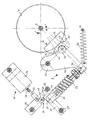
- the figure shows a top view of the structure of the safety device according to the invention. 2 with an axis of a rotatable device 4, for example a revolving door, not shown.
- a stop device 6 Arranged at a distance from the axis 2 is a stop device 6 in the form of a cam disk 14.
- the stop device 6 has two stop points spaced apart from one another in the form of cams 10 and 12, the stop surfaces 16, 18 of the cams 10, 12 being of rounded design.
- a roller 20 of a holding device 8 is arranged in the area between the cams 10 and 12. The stop device 6 is firmly attached to the device 4.
- the holding device 8 is constructed in the manner of a four-bar linkage and consists of a plate 60 which has the roller 20 and is movably held via a fixed starting link 22.
- a plate 24 is connected to the plate 60 via a joint 24 Compression spring rod 52 articulated.
- the other end of the compression spring rod 52 opposite the joint 24 is also articulated to a lever 58 via a further joint 26.
- the lever 58 in turn is attached via a fixed end joint 28.
- the holding device 8 accordingly represents a four-bar joint, each consisting of a fixed start or end joint 22, 28 and two movable joints 24, 26 arranged between them. If the holding device 8 is not prevented from moving by a stop, the holding device 8 can be when force is exerted, swing away unhindered, in which the lever 58 and the plate 60 pivot and thereby take the compression spring rod 52 with them.
- the holding device 8 since it is the task of the holding device 8 to prevent the device 4 from pivoting about the axis 2, the holding device 8 must be determined by certain measures to the extent that the above-described pivoting out of the holding device 8 is prevented.
- the swiveling out without disability is referred to as the inactivation of the holding device 8.
- the holding device 8 is fixed via a first stop 32 and a second stop 34.
- the holding device 8 is guided to the first stop 32 via a tension spring 30 which is arranged at the connection point between the plate 60 and the compression spring 52, the other End of the tension spring 30 is fixed to a pin 62, for example.
- the spring force of the tension spring 30 only has to be designed so that the tension spring 30 leads the holding device 8 securely up to a contact with the first stop 32.
- the anchor device 8 lies on a cantilever finger 64 on the first stop 32, which is designed, for example, as a bolt. Accordingly, there is a kind of pretensioning of the holding device 8 on the first stop 32 due to the tension spring 30.
- the first stop 32 prevents the holding device 8 from pivoting away without force when the device 4 moves in the direction of arrow A. In this case, the roller 20 bears against the cam 12, the holding device 8 initially preventing the device 4 from further turning in the direction of the arrow A by the first stop 32.
- a second stop 34 is provided, which rests on the lever 58 in the region of the free end 50 of the lever 58 via a pressure roller 48 as a stop element.
- the holding device 8 is intended to prevent rotation of the device 4, however, only up to a predetermined force acting on the holding device 8 via the roller 20. In the event of a force exceeding the predetermined force, at least part of the holding device 8 should deflect, so that the roller 20 can slide over one of the two cams 10, 12, in order to thereby avoid damage to the bearing parts and the material of the device 4.
- the desired pivoting away of the holding device 8 or a part of the holding device 8 is made possible by the compression spring rod 52 which, depending on the direction of rotation of the device 4, either compresses or pulls apart. For a certain amount of shortening or lengthening of the pressure rod 52, the roller 20 can one of the two cams 10, 12th exceed and thus allow the pivoting movement of the device 4.
- the setting of the spring force of the compression spring 52 takes place via a clamping bolt 54, which can be adjusted by means of an Allen screw 56.
- a clamping bolt 54 which can be adjusted by means of an Allen screw 56.
- the holding device 8 must not hinder or complicate the pivoting of the device 4 in the event that a person wishes to pass through the device 4, which is designed, for example, as a pivot door, not shown, in order to enter or exit a building. Even in a possible danger, e.g. in the event of fire, it must be ensured that people can get out of the building freely through the device 4. This is achieved in that at least one of the two stops 32, 34 can be brought out of engagement with the holding device 8.
- the second stop 34 is designed as a movable stop in order to allow the device 4 to pivot freely in the direction of the arrow B.
- the second stop 34 consists of a displaceable bearing block 36, at the end of which, facing the lever 58, a pressure roller 48 is fastened.
- the pivoting away of the bearing block 36 is made possible by a rod 42 which is connected to it in an articulated manner.
- the rod 42 is part of a pivoting device 40, which from the aforementioned rod 42 and an electric solenoid 44.
- the electric lifting magnet only moves the rod 42 in the direction of the lever 58 in the activated state, so as to bring the bearing block 36 or the pressure roller 48 into engagement with the lever 58. Extending the rod 42 only in the activated state of the electric lifting magnet 54 is therefore provided that in the event of a power failure the bearing block 36 or the pressure roller 48 is automatically disengaged from the lever 58.
- This pivoting back of the bearing block 36 in the direction of the electric lifting magnet 44 is supported by a tension spring 46 which is biased in the activated state of the electric lifting magnet 44.
- the compression spring 46 pulls the rod 42 back in the direction of the electric lifting magnet 44 and thus pivots the bearing block 36 and thereby also the pressure roller 48 away from the area of the lever 58.
- the pressure roller 48 is arranged such that even a slight movement of the rod 42 in the direction of the electric lifting magnet 44 enables the holding device 8 to be pivoted away without force.
- the center of the pressure roller 48 is only a short distance from the free end 50 of the lever 58.
- the holding device 8 can be pivoted without force by using the bearing block 36 during the pivoting movement the pressure roller 48 is pivoted.
- the electric lifting magnet 44 can only be activated when the roller 20 is located between the cams 10 and 12. This can be ensured by a simple circuit with, for example, a sensor.
- the roller 20 is arranged at a distance from the stop device 6 or the cam disk 14.
- the activation angle resulting from the spacing of the cams 10 and 12 ensures that the device 4 is not held immovably by the holding device 8.
- the device 4 can start moving a certain amount before the bearing pin 20 abuts the cam 12.
- the device 4 can be accelerated and a greater force can be exerted on the holding device 8, and thus the device 4 can also be pivoted in an emergency in spite of the activated holding device 8. This also applies in the event that the second stop 34 cannot be pivoted out of the stop position with the lever 58 due to certain circumstances.
- the holding device 8 can be activated automatically via the electric lifting magnet 44.
- the second stop 34 When there is no wind, for example, it is not necessary for the second stop 34 to be brought into engagement with the lever 58.
- the safety device can be activated via an electrical circuit by pivoting the bearing block 36 into its position shown in the figure.
- a detected wind speed can, for example, control the linear motor for adjusting the spring force of the compression spring 52 depending on the wind strength and thus automatically bias it to a specific value.
Landscapes
- Engineering & Computer Science (AREA)
- Mechanical Engineering (AREA)
- Civil Engineering (AREA)
- Structural Engineering (AREA)
- Closing And Opening Devices For Wings, And Checks For Wings (AREA)
- Extensible Doors And Revolving Doors (AREA)
- Power-Operated Mechanisms For Wings (AREA)
Applications Claiming Priority (3)
| Application Number | Priority Date | Filing Date | Title |
|---|---|---|---|
| DE4036881 | 1990-11-19 | ||
| DE19904036881 DE4036881A1 (de) | 1990-11-19 | 1990-11-19 | Sicherungsvorrichtung fuer eine um eine achse verschwenkbare bzw. drehbare vorrichtung |
| PCT/EP1991/002183 WO1992008865A1 (de) | 1990-11-19 | 1991-11-19 | Sicherungsvorrichtung für eine um eine achse verschwenkbare bzw. drehbare vorrichtung |
Publications (2)
| Publication Number | Publication Date |
|---|---|
| EP0511357A1 EP0511357A1 (de) | 1992-11-04 |
| EP0511357B1 true EP0511357B1 (de) | 1995-03-15 |
Family
ID=6418575
Family Applications (1)
| Application Number | Title | Priority Date | Filing Date |
|---|---|---|---|
| EP91920457A Expired - Lifetime EP0511357B1 (de) | 1990-11-19 | 1991-11-19 | Sicherungsvorrichtung für eine um eine achse verschwenkbare bzw. drehbare vorrichtung |
Country Status (4)
| Country | Link |
|---|---|
| EP (1) | EP0511357B1 (enExample) |
| JP (1) | JP2652815B2 (enExample) |
| DE (1) | DE4036881A1 (enExample) |
| WO (1) | WO1992008865A1 (enExample) |
Families Citing this family (7)
| Publication number | Priority date | Publication date | Assignee | Title |
|---|---|---|---|---|
| ZA94606B (en) * | 1993-02-04 | 1994-07-22 | Intechn Technologies C C | Turnstyle control mechanism |
| DE4333450C2 (de) * | 1993-09-30 | 1996-04-25 | Gartner & Co J | Karusselldrehtürflügel-Schließer |
| SE503901C2 (sv) * | 1995-01-18 | 1996-09-30 | Entre Matic Ab | Kraftöverförande anordning vid mekaniskt manövrerade dörrar och liknande |
| NL1003383C2 (nl) * | 1996-06-20 | 1997-12-23 | Boon Edam Bv | Draaideur. |
| DE19945739C2 (de) * | 1999-09-23 | 2002-07-25 | Dorma Gmbh & Co Kg | Vorrichtung zur Sicherung der Türflügel einer mehrflügeligen Karusselltür gegen ungewolltes Auslenken |
| DE19945738B4 (de) * | 1999-09-23 | 2004-09-02 | Dorma Gmbh + Co. Kg | Karusselltür |
| WO2002064924A2 (de) | 2001-02-09 | 2002-08-22 | Dorma Gmbh + Co. Kg | Sicherungvorrichtung gegen ungewolltes auslenken einer türflügel |
Family Cites Families (4)
| Publication number | Priority date | Publication date | Assignee | Title |
|---|---|---|---|---|
| US1983396A (en) * | 1933-11-07 | 1934-12-04 | Gen Bronze Corp | Revolving door |
| US2030547A (en) | 1934-04-06 | 1936-02-11 | Internat Door Company | Braceless panic release, roller latching, revolving door hardware |
| US3656787A (en) * | 1970-07-23 | 1972-04-18 | H B Ives Co The | Door stop and holder |
| DE3815195A1 (de) * | 1988-05-04 | 1989-11-16 | Mbm Metallbau Moeckmuehl Gmbh | Motorisch betriebene drehtuer mit auslenkbaren fluegeln |
-
1990
- 1990-11-19 DE DE19904036881 patent/DE4036881A1/de active Granted
-
1991
- 1991-11-19 WO PCT/EP1991/002183 patent/WO1992008865A1/de not_active Ceased
- 1991-11-19 EP EP91920457A patent/EP0511357B1/de not_active Expired - Lifetime
- 1991-11-19 JP JP4500295A patent/JP2652815B2/ja not_active Expired - Fee Related
Also Published As
| Publication number | Publication date |
|---|---|
| DE4036881A1 (de) | 1992-05-21 |
| JP2652815B2 (ja) | 1997-09-10 |
| EP0511357A1 (de) | 1992-11-04 |
| DE4036881C2 (enExample) | 1992-09-17 |
| WO1992008865A1 (de) | 1992-05-29 |
| JPH05505434A (ja) | 1993-08-12 |
Similar Documents
| Publication | Publication Date | Title |
|---|---|---|
| AT412411B (de) | Elektromechanische feststellvorrichtung für türflügel mit einem türschliesser | |
| DE4016283C1 (enExample) | ||
| EP2352893B1 (de) | Arretiereinheit für einen türschliesser, türschliesssystem, verwendung einer arretiereinheit und verfahren zum arretieren einer tür | |
| DE3431983C2 (enExample) | ||
| EP1495203B1 (de) | Tor mit sicherungseinrichtung | |
| DE69909975T2 (de) | Vorrichtung zum Betätigen des Visiers von Helmen für Motorradfahrer und dergleichen | |
| EP0511357B1 (de) | Sicherungsvorrichtung für eine um eine achse verschwenkbare bzw. drehbare vorrichtung | |
| DE19545401A1 (de) | Schließfolgesteuerung für eine zweiflügelige Tür | |
| DE3604083C2 (de) | Feststellvorrichtung für Türflügel mit einem Türschließer | |
| DE3507305C2 (de) | Vorrichtung zur Betätigung eines Freigaberiegels | |
| DE10107461C2 (de) | Schließfolgeregler | |
| DE1800270A1 (de) | Geschwindigkeitsbegrenzer fuer Aufzuege | |
| DE2548069C3 (enExample) | ||
| CH641521A5 (en) | Setting-out device for windows or doors | |
| EP0072972B1 (de) | Selbstschalter | |
| EP1233132B1 (de) | Schliessfolgeregler | |
| DE2462548C3 (de) | Vorderbacken für Sicherheitsskibindungen | |
| EP0288430A1 (de) | Sperrmechanismus, insbesondere für die Höhenverstellung von Tischplatten | |
| EP0505350A1 (de) | Drehscheiben-Schliessfolge- und Verriegelungseinrichtung | |
| DE102019109351A1 (de) | Netzhalter und Tischtennis-Netzgarnitur mit Netzhalter | |
| DE102006041922B4 (de) | Feststeller für ein schwenkbares Bauteil, insbesondere eine Fahrzeugtür | |
| DE1478149A1 (de) | Vorderbacken fuer Sicherheitsskibindungen | |
| EP2886770B1 (de) | Vorrichtung zur Regelung der Schließfolge einer zweiflügeligen Tür | |
| DE69909146T2 (de) | Vorrichtung zum Verschwenken und Stabilisieren eines Aussenrückblickspiegel | |
| EP4353930A1 (de) | System zur verschiebung und verriegelung eines schiebeelements |
Legal Events
| Date | Code | Title | Description |
|---|---|---|---|
| PUAI | Public reference made under article 153(3) epc to a published international application that has entered the european phase |
Free format text: ORIGINAL CODE: 0009012 |
|
| 17P | Request for examination filed |
Effective date: 19920619 |
|
| AK | Designated contracting states |
Kind code of ref document: A1 Designated state(s): DE FR GB |
|
| 17Q | First examination report despatched |
Effective date: 19940110 |
|
| GRAA | (expected) grant |
Free format text: ORIGINAL CODE: 0009210 |
|
| AK | Designated contracting states |
Kind code of ref document: B1 Designated state(s): FR GB |
|
| GBT | Gb: translation of ep patent filed (gb section 77(6)(a)/1977) |
Effective date: 19950313 |
|
| ET | Fr: translation filed | ||
| PLBE | No opposition filed within time limit |
Free format text: ORIGINAL CODE: 0009261 |
|
| STAA | Information on the status of an ep patent application or granted ep patent |
Free format text: STATUS: NO OPPOSITION FILED WITHIN TIME LIMIT |
|
| 26N | No opposition filed | ||
| REG | Reference to a national code |
Ref country code: GB Ref legal event code: IF02 |
|
| PGFP | Annual fee paid to national office [announced via postgrant information from national office to epo] |
Ref country code: GB Payment date: 20051116 Year of fee payment: 15 |
|
| PGFP | Annual fee paid to national office [announced via postgrant information from national office to epo] |
Ref country code: FR Payment date: 20051118 Year of fee payment: 15 |
|
| GBPC | Gb: european patent ceased through non-payment of renewal fee |
Effective date: 20061119 |
|
| REG | Reference to a national code |
Ref country code: FR Ref legal event code: ST Effective date: 20070731 |
|
| PG25 | Lapsed in a contracting state [announced via postgrant information from national office to epo] |
Ref country code: GB Free format text: LAPSE BECAUSE OF NON-PAYMENT OF DUE FEES Effective date: 20061119 |
|
| PG25 | Lapsed in a contracting state [announced via postgrant information from national office to epo] |
Ref country code: FR Free format text: LAPSE BECAUSE OF NON-PAYMENT OF DUE FEES Effective date: 20061130 |