EP0510683B1 - Blood collecting tube - Google Patents
Blood collecting tube Download PDFInfo
- Publication number
- EP0510683B1 EP0510683B1 EP92107049A EP92107049A EP0510683B1 EP 0510683 B1 EP0510683 B1 EP 0510683B1 EP 92107049 A EP92107049 A EP 92107049A EP 92107049 A EP92107049 A EP 92107049A EP 0510683 B1 EP0510683 B1 EP 0510683B1
- Authority
- EP
- European Patent Office
- Prior art keywords
- stopper
- tubular member
- projections
- blood collecting
- collecting tube
- Prior art date
- Legal status (The legal status is an assumption and is not a legal conclusion. Google has not performed a legal analysis and makes no representation as to the accuracy of the status listed.)
- Expired - Lifetime
Links
Images

Classifications
-
- B—PERFORMING OPERATIONS; TRANSPORTING
- B01—PHYSICAL OR CHEMICAL PROCESSES OR APPARATUS IN GENERAL
- B01L—CHEMICAL OR PHYSICAL LABORATORY APPARATUS FOR GENERAL USE
- B01L3/00—Containers or dishes for laboratory use, e.g. laboratory glassware; Droppers
- B01L3/50—Containers for the purpose of retaining a material to be analysed, e.g. test tubes
- B01L3/508—Rigid containers without fluid transport within
- B01L3/5082—Test tubes per se
- B01L3/50825—Closing or opening means, corks, bungs
-
- A—HUMAN NECESSITIES
- A61—MEDICAL OR VETERINARY SCIENCE; HYGIENE
- A61B—DIAGNOSIS; SURGERY; IDENTIFICATION
- A61B5/00—Measuring for diagnostic purposes; Identification of persons
- A61B5/15—Devices for taking samples of blood
- A61B5/150007—Details
- A61B5/150015—Source of blood
- A61B5/15003—Source of blood for venous or arterial blood
-
- A—HUMAN NECESSITIES
- A61—MEDICAL OR VETERINARY SCIENCE; HYGIENE
- A61B—DIAGNOSIS; SURGERY; IDENTIFICATION
- A61B5/00—Measuring for diagnostic purposes; Identification of persons
- A61B5/15—Devices for taking samples of blood
- A61B5/150007—Details
- A61B5/150351—Caps, stoppers or lids for sealing or closing a blood collection vessel or container, e.g. a test-tube or syringe barrel
-
- A—HUMAN NECESSITIES
- A61—MEDICAL OR VETERINARY SCIENCE; HYGIENE
- A61B—DIAGNOSIS; SURGERY; IDENTIFICATION
- A61B5/00—Measuring for diagnostic purposes; Identification of persons
- A61B5/15—Devices for taking samples of blood
- A61B5/153—Devices specially adapted for taking samples of venous or arterial blood, e.g. with syringes
- A61B5/154—Devices using pre-evacuated means
-
- B—PERFORMING OPERATIONS; TRANSPORTING
- B01—PHYSICAL OR CHEMICAL PROCESSES OR APPARATUS IN GENERAL
- B01L—CHEMICAL OR PHYSICAL LABORATORY APPARATUS FOR GENERAL USE
- B01L2300/00—Additional constructional details
- B01L2300/04—Closures and closing means
- B01L2300/041—Connecting closures to device or container
- B01L2300/044—Connecting closures to device or container pierceable, e.g. films, membranes
Definitions
- the present invention relates to a blood collecting tube and, more particularly, an evacuated blood collecting tube with an improved sealing assembly capable of being easily fitted to a bottom-closed tubular member and having a low resistance to insertion and removal of a piercing needle for collection of blood sample.
- the blood collecting tube generally comprises a bottom-closed tubular member, i.e., a tubular member closed at one end and open at the other end, which is evacuated and sealed by a stopper fitted in the open end of the tubular member to retain its vacuum.
- tubular members are made of glass at the beginning, but the most of recent tubular members are made of synthetic resins as the glass tubes are easy to break and cause the problem of waste disposal.
- Such blood collecting tubes are disclosed, for example, in U.S. patents No. 3,734,080 and 3,890,955, and Japanese patent publication No. Heisei 2-49099.
- the blood collecting tubes widely used comprises a bottom-closed tubular member made of synthetic resins having a small gas-permeability or a good gas-barrier property, such as polyethylene terephthalate for example, the tubular member being evacuated and closed by fitting a stopper made of elastomeric material such as butyl rubber or natural rubber in the open end of the tubular member under a reduced pressure.
- a stopper made of elastomeric material such as butyl rubber or natural rubber
- the above blood collecting tubes include the following problems as the stopper is held in place by frictional resistance between an annular outer surface of the stopper and an annular inner surface of the evacuated tube.
- the evacuated blood collecting tube in combination with a holder having a double ended cannula of which one end is adapted to be pierced into a blood vessel while the other end is adapted to be penetrated into the stopper.
- blood samples are collected by firstly piercing one end of the cannula of the holder into a blood vessel of the patient, inserting the other end of the cannula into the tube through a diaphragm portion of the stopper, removing the cannula from the blood vessel, and then removing the holder from the blood collecting tube containing a collected blood sample.
- the stopper Since the stopper possesses a large resistance to insertion of cannula, it is required to use a large-sized cannula to prevent it from bending during insertion of the cannula into the stopper. The greater the diameter of cannula, the greater is the resistance to insertion and removal of the cannula. Thus, there is such fear that the stopper may slip out of the tube at the time of removal of holder if the frictional resistance between the stopper and cannula is greater than the frictional resistance between the tubular member and stopper. Further, the use of a large-sized cannula would load the patient at the time of collection of blood samples.
- the rubber stopper removed from the tubular member is occasionally reused to close the open end of the tubular member.
- the insertion of the stopper causes compression of air in the bottom-closed tubular member, which causes a phenomenon that the stopper hops up.
- the rubber stopper occasionally comes off as the frictional resistance between the stopper and the needle pierced therein exceeds the frictional resistance between the tubular member and the stopper, resulting in leakage of the blood sample in the analyzer.
- Japanese patent publication No. Heisei 2-25611 discloses a blood collecting tube with an improved closure assembly comprising an annular stopper body with an upper outwardly extending annular flange portion and a lower annular skirt portion, and a flexible cap body for mounting on the annular stopper body.
- This closure assembly makes it possible to reduce the incidence of contamination of the user of the evacuated tube, but it includes problems similar to those disclosed in the aforesaid U.S. patents.
- Japanese patent unexamined publication No. Heisei 2-212768 discloses a blood collecting tube of a thin film type composed of a tubular member closed at one end and open at the other end, a cap member removably fitted on the open end of the tubular member with a threaded structure, and a sealing member arranged between the cap member and the open end of the tubular member to seal the opening of the tubular member, said sealing member having a gas barrier film such as an aluminum laminated film and a re-sealing member made of natural rubber and bonded to the gas barrier film member in an overlapped relation.
- the blood collecting tube of the kind has various advantages, but it is impossible to remove the sealing member and cap member with one hand as the cap is screw-mounted on the tubular member.
- US-A-4 967 919 discloses a blood collecting tube having the features of the pre-characterising part of claim 1.
- Further object of the present invention is to provide an evacuated blood collecting tube which can be used for analysis of blood samples with an automatic blood analyzer, without causing leakage of the blood sample into the analyzer.
- Another object of the present invention is to provide an evacuated blood collecting tube which can be manufactured in the same manner as that of the evacuated blood collecting tubes of glass.
- a blood collecting tube comprising a tubular member with one bottom end closed and the other end being open, a stopper having an upper flange portion and a lower annular skirt portion extending from the upper flange portion, the skirt portion of said stopper being fitted in the open end of said tubular member, and a cap member placed on said tubular member to increase the degree of coupling between said tubular member and stopper fitted therein, said cap member having projections on its inside wall, and a bore formed in its closed end for insertion of needles, characterized in that said tubular member is provided at the circumference of its open end with an annular flange so designed that its diameter increases in the direction toward the closed bottom to form a groove between the flange of said tubular member and the flange of said stopper, and that said cap member and is provided with at least two projections on its inside wall at different levels, one of said at least two projections being engaged with the flange of said tubular member, the other projection being engaged with the f
- the cap member has upper and lower projections in the form of a half-ring. These upper and lower projections are arranged in an opposite relation.
- the cap member is provided with two kind of projections extending inwardly from its inside wall, one projection being formed in the form of a ring, the other projections being formed in the form of a segment of a ring and axially spaced from the former.
- the cap member is provided with at least three pairs of upper projections with a triangular cross section and at least three lower projections with a triangular cross section, said at least three pairs of upper projections being spaced equally round the inner circumference of said cap member, said upper projections in each pair being spaced from each other, each of said lower projections being arranged below a space formed between said two projections in each pair.
- the cap member may be further provided with an outwardly extending projection on a circumferential part of its closed end, said projection being positioned on the side of the other projection.
- the outwardly extending projection is in the form of a half-ring.
- the stopper is provided at its flange portion with an upper recess and at its annular skirt portion with a lower recess to define a diaphragm portion for insertion of hollow needles between them.
- the diaphragm portion is designed so as to have a thickness of 0.5 to 2.5 mm.
- the skirt portion of the stopper is designed so as to have a length of 2 to 5 mm.
- the tubular member employed in the present invention may made of glass or a synthetic resin.
- Preferred synthetic resins are mixtures composed of xylylene-containing polyamide and polyethylene terephthalate and containing one or more transition metal salts.
- the xylylene-containing polyamide may be produced by polymerization of at least one dicarboxylic acid and at least one xylylenediamine.
- the dicarboxylic acid includes, without being limited to, those such as adipic acid, pimelic acid, stearic acid, azelaic acid and sebacic acid.
- the above xylylenediamine includes, without being limited to, m-xylylenediamine, a mixture of m-xylylenediamine and p-xylylenediamine, a mixture of m-xylylenediamine and hexamethylenediamine.
- Typical transition metal salts includes, without being limited to, cobalt stearate, cobalt acetate, cobalt naphthalate, nickel acetylacetate, nickel chloride, rhodium chloride.
- the bottom-closed tubular members are to be made by a mixture of xylylene-containing polyamide and polyethylene terephthalate containing one or more transition metal salts
- blue or violet dye or organic pigments are preferred to incorporate blue or violet dye or organic pigments into pellets of the mixture to improve the transparency of the tubular members.
- Typical dyes or pigments include blue No. 1 (C.I. 42090), blue No. 2 (C.I. 73015), blue No. 201 (C.I. 73000), blue No. 202 (C.I. 42052), blue No. 203 (C.I. 42052), blue No. 204 (C.I. 16982), blue No. 403 and violet No. 201 (C.I. 60725).
- the stopper may be made of butyl rubber, natural rubber or a mixture thereof and can be produced by compression molding with a suitable rubber material.
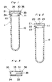
- a blood collecting tube 1 embodying the present invention which comprises a tubular member 10 closed at one end (or a bottom) and open at the other end (or a top), an elastomeric stopper 20 fitted in the open end of the tubular member, and a cap member 30 fitted on the top of tubular member 10.
- the bottom-closed tubular member 10 is provided at its top with an outwardly extending annular flange 11 which is downwardly spread out like an unfolded fan.
- Such a bottom-closed tubular member can be produced with ease by injection molding, using a synthetic resin.
- the stopper 20 has a peripheral flange 21 overlying the open end of the tubular member 10, and an annular skirt portion 22 fitted in the opening of the tubular member 10 to form a sealing between stopper 20 and tubular member 10.
- the skirt portion 22 is so designed as to have a length of 2.5 to 5.0 mm.
- the stopper 20 has a cylindrical recess 23 in the central part of its skirt portion and an upper recess 24 in the central part of the flange 21. Both recesses 23 and 24 define a thickness of a diaphragm portion 25 formed between them.
- the diaphragm portion is so designed as to have a thickness of 0.5 to 2.5 mm to allow easy insertion and removal of a hollow needle used for blood collection or of a blood sample collection needle used in an automatic blood analyzer.
- the cap member 30, as illustrated in Fig. 3, has a closed end 31 and an open end 32.
- the closed end 31 is provided at its central portion with a bore 33 for insertion and removal of a hollow needle or cannula for blood collection or a blood sample collection needle used in an automatic blood analyzer.
- the cap member 30 is provided with two half-ring projections 34 and 35 each of which extends inwardly from the inner peripheral surface of the cap member 30 and terminates at or around the outer surface of the tubular member 10.
- the projections 34 and 35 are so designed that they are in a diametrical relation and arranged at different levels so that the lower projection 34 is engaged with the lower end of the flange 11 of tubular member 10, while the upper projection 35 is engaged at its upper surface with the lower surface of the flange 21 of stopper 20 and held between the groove formed between the flange 11 of tubular member 10 and the flange 21 of stopper 20.
- the cap member 30 is also provided with a segmental flange 36 extending outwardly from the head portion of the cap member, indicating the direction for removal of the cap member from the tubular member and serving as a pushing portion.
- a difference between an inside diameter of the semicircular projection 34 or 35 and inside diameter of the opening of the cap member 30 is about 1 mm.
- Such a cap member may be produced with ease by injection molding, using multipurpose plastics such as polyethylene, polypropylene and the like.
- the bottom-closed tubular member 10 is firstly evacuated to a suitable vacuum in a vacuum vessel, sealed by fitting the stopper 20 into the opening of the tubular member 10. Then, the cap member 30 is fitted on the open end of the tubular member 10. The cap member may be fitted to the tubular member 10 simultaneously with fitting of the stopper 20. This processes may be carried out by a conventionally known manufacturing line for evacuated blood collecting tube of glass.
- the stopper can be removed from the opening of the tubular member along with the cap member by pushing upwardly projection 35 of the cap member as the annular flange 21 of the stopper is held between the head portion and the projection 35 of the cap member.
- the stopper 20 can be removed together with the cap member by one hand with ease.
- the projection 34 of the cap member engages the flange 11 of the tubular member 10, thus making it possible to prevent the stopper from hopping-up phenomenon.
- the inward projections of the cap member are engaged with the flange of the tubular member and the flanged stopper is held in place by means of the cap member and the tubular member, thus making it possible to prevent the stopper from slipping out of place when removing a hollow needle pierced in the stopper.
- the combination of the cap member and the flanged tubular member makes it possible to use a stopper with a shortened annular skirt portion and a thin diaphragm portion with a thickness of 0.5 to 2.5 mm.
- a bottom-closed tubular member made of a mixture of xylylene-containing polyamide and polyethylene terephthalate and containing one or more transition metal salts.
- the stopper since the stopper has a low resistance to insertion and removal of a piercing needle, it is possible to apply the blood collecting tube to blood examination with an automatic analyzer of the kind wherein a hollow needle of the analyzer is directly pierced in the stopper of the blood collecting tube to introduce blood to be examined into the analyzer.
- decrease in the degree of vacuum of the blood collecting tube may be minimized by use of glass as a material for the tubular member, during storage for a long period of time. If the material for tubular member is not glass, it is preferred to use a mixture composed of poly-m-xylylene adipamide and polyethylene terephthalate and containing one or more organic acid salts of transition metals to prevent the evacuated blood collecting tube from decrease of the degree of vacuum during storage.
- the blood collecting tube 1' comprises a bottom-closed tubular member 10, a elastomeric stopper 20 fitted in the open end of the tubular member, and a cap member 30' fitted on the top of tubular member 10.
- Bottom-closed tubular member 10 has the same structure as that of bottom-closed tubular member 10 shown in Fig. 1.
- elastomeric stopper 20 has the same structure as that of elastomeric stopper 20 of Fig. 1.
- cap member 30' has closed end 31 and open end 32.
- the closed end 31 is provided at its central portion with bore 33 for insertion and removal of a hollow needle for blood collection or a blood sample collection needle used in an automatic blood analyzer.
- Cap member 30' is provided on its inside wall with three arched projections 34 spaced equally round the inner circumference of cap member 30', and annular projection 35 spaced upwardly from projections 34. Arched projections 34 and annular projection 35 are so designed that they have an inner diameter smaller by about 1 mm than that of cap member 30'.
- stopper 20 When sealing the open end of bottom-closed tubular member 10, stopper 20 is firstly fitted in the open end of tubular member 10 and cap member 30' is fitted on bottom-closed tubular member 10.
- cap member 30' When cap member 30' is fitted in place, its lower projections 34 are engaged with annular flange 11 of tubular member 10, while upper annular projection 35 is engaged at its upper surface with the lower surface of flange 21 of stopper 20 and held between the groove formed between flanges 11 and 21 of tubular member 10 and stopper 20.
- annular flange 21 of stopper 20 is urged to the end surface of tubular member 10 by cap member 30' and housed in a space formed between the lower surface of head portion 31 and the upper surface of annular projection 35 of cap member 30'.
- stopper 20 Since lower projections 34 of cap member 30' are engaged with annular flange 11 of tubular member 10, and since the flange of stopper 20 is forced to the end surface of tubular member 10 by cap member 30', it is possible to increase engagement between bottom-closed tubular member 10 and topper 20.
- stopper 20 is so designed as to have annular skirt portion 22 with a length of 2 to 5 mm, it is possible remove the stopper together with cap member 30' from the tubular member by diagonally pushing up the cap member in any directions. The thus removed cap member having the stopper can be re-used to seal the bottom-closed tubular member.
- projection 35 is provided around the inner surface of the cap member and located above arched projections 34, but it may be located below arched projections 34. Also, projection 35 may be divided into two or more arched projections spaced equally round the inner circumference of cap member 30'.
- Fig. 6 shows another form of a cap member used to increase the fit between the stopper and the bottom-closed tubular member.
- This cap member 30'' is provided with four pairs of upper projections with a triangular cross section and four lower projections with a triangular cross section.
- the four pairs of upper projections 35 are spaced equally round the circumference of the inside wall of the cap member.
- the upper two projections 35a, 35b in each pair are spaced from each other by a distance corresponding to a width of the lower projection 34.
- Each lower projection 34 is formed below a space formed between two upper projections in each pair.
- each stopper having a diaphragm portion with a thickness of 1.0, 1.5 2.0 or 6.0 mm.
- the stopper having a diaphragm portion with a thickness of 6.0 mm is out of the scope of the present invention.
- Cobalt stearate is added to a mixture composed of 100 parts by weight of polyethylene terephthalate, 1 part by weight of poly-m-xylylene adipamide and 2 parts by weight of a master pellet containing 1 % of a dye (anthraquinon derivative) so that the resultant mixture contains 4 ppm of cobalt.
- a master pellet containing 1 % of a dye (anthraquinon derivative) so that the resultant mixture contains 4 ppm of cobalt.
- the bottom-closed tubular members were evacuated so as to have an initial blood collecting capacity of 2 ml or 5 ml and then sealed in vacuum by fitting the stopper prepared in Example 1 in the open end of the tubular member to prepare evacuated tubes for measurement of the vacuum retaining property.
- the stopper used in the example has a diaphragm portion with a thickness of 1.0 or 2.0 mm.
- each tube B was evacuated so as to have an initial blood collecting capacity of 2 ml or 5 ml and then sealed in vacuum by fitting the stopper prepared in Example 1 in the open end of the tubular member.
- the stoppers used in this comparative example have the diaphragm portion with a thickness of 6 mm.
- Example 2 For each kind of evacuated tubes prepared in Example 2 and comparative example 1, ten tubes were subjected to measurement of an amount of water absorbed in the tube just after their production to determine a mean value (A) of the initial blood collecting ability. Also, another ten tubes of each kind were put in storage for 1 year and then subjected to measurement of an amount of water absorbed in the tube after storage to determine a mean value (B) of the blood collecting ability after storage. The vacuum retaining rate was determined as a ratio of B/A. Results are shown in Table 2. In this table, asterisked specimens are those out of the scope of the present invention. Table 2 No. Evacuated tube Rated Initial blood collecting ability B/A (%) Vessel Stopper 1 A No. 1 2 ml 106.8 2 A No.
- the evacuated tubes are improved in the vacuum retaining property by use of a mixture including polyethylene terephthalate, poly-m-xylylene adipamide and containing cobalt as a material for bottom-closed tubular members, as compared with those made of polyethylene terephthalate.
- stoppers of Fig. 4 having a diaphragm portion with a thickness of 2.0 mm or 6 mm and an annular skirt portion with a length of 3, 5 or 10 mm.
- bottom-closed tubular members with no flange were prepared in the same manner as above.
- cap members of Fig. 5 were prepared by injection molding.
- the bottom-closed tubular members were evacuated so as to have an initial blood collecting capacity of 2 ml or 5 ml and then sealed in vacuum by fitting the stopper in the open end of each tubular member.
- the cap member was then fitted on each of the evacuated tubular member to prepare evacuated blood collecting tubes listed in Table 3.
Landscapes
- Health & Medical Sciences (AREA)
- Life Sciences & Earth Sciences (AREA)
- Hematology (AREA)
- General Health & Medical Sciences (AREA)
- Public Health (AREA)
- Heart & Thoracic Surgery (AREA)
- Veterinary Medicine (AREA)
- Physics & Mathematics (AREA)
- Animal Behavior & Ethology (AREA)
- Biophysics (AREA)
- Pathology (AREA)
- Engineering & Computer Science (AREA)
- Biomedical Technology (AREA)
- Surgery (AREA)
- Medical Informatics (AREA)
- Molecular Biology (AREA)
- Chemical & Material Sciences (AREA)
- Clinical Laboratory Science (AREA)
- Analytical Chemistry (AREA)
- Chemical Kinetics & Catalysis (AREA)
- Measurement Of The Respiration, Hearing Ability, Form, And Blood Characteristics Of Living Organisms (AREA)
- Investigating Or Analysing Biological Materials (AREA)
- Medical Preparation Storing Or Oral Administration Devices (AREA)
- Sampling And Sample Adjustment (AREA)
Applications Claiming Priority (4)
| Application Number | Priority Date | Filing Date | Title |
|---|---|---|---|
| JP125483/91 | 1991-04-26 | ||
| JP3125483A JP2500708B2 (ja) | 1991-04-26 | 1991-04-26 | 採血管 |
| JP314041/91 | 1991-10-31 | ||
| JP3314041A JPH0638792B2 (ja) | 1991-04-26 | 1991-10-31 | 採血管 |
Publications (2)
| Publication Number | Publication Date |
|---|---|
| EP0510683A1 EP0510683A1 (en) | 1992-10-28 |
| EP0510683B1 true EP0510683B1 (en) | 1995-12-13 |
Family
ID=26461915
Family Applications (1)
| Application Number | Title | Priority Date | Filing Date |
|---|---|---|---|
| EP92107049A Expired - Lifetime EP0510683B1 (en) | 1991-04-26 | 1992-04-24 | Blood collecting tube |
Country Status (5)
| Country | Link |
|---|---|
| US (1) | US5246434A (cs) |
| EP (1) | EP0510683B1 (cs) |
| JP (2) | JP2500708B2 (cs) |
| CZ (1) | CZ281788B6 (cs) |
| DE (1) | DE69206669T2 (cs) |
Cited By (1)
| Publication number | Priority date | Publication date | Assignee | Title |
|---|---|---|---|---|
| US11266569B2 (en) | 2012-12-21 | 2022-03-08 | Peter Skufca | Primary packaging for storage and administration of medical and pharmaceutical compounds |
Families Citing this family (29)
| Publication number | Priority date | Publication date | Assignee | Title |
|---|---|---|---|---|
| US5494170A (en) * | 1993-05-06 | 1996-02-27 | Becton Dickinson And Company | Combination stopper-shield closure |
| WO1995009362A1 (en) * | 1993-09-30 | 1995-04-06 | Fujisawa Pharmaceutical Co., Ltd. | Urine sampling vessel |
| US5662127A (en) * | 1996-01-17 | 1997-09-02 | Bio-Plas, Inc. | Self-contained blood withdrawal apparatus and method |
| US6001087A (en) * | 1996-09-30 | 1999-12-14 | Becton Dickinson And Company | Collection assembly with a reservoir |
| DE10028482B4 (de) * | 2000-06-08 | 2004-09-16 | Kabe-Labortechnik Gmbh | Behältnis für die Entnahme von Proben und insbesondere Blutproben |
| SE0202220L (sv) * | 2002-07-16 | 2004-01-17 | Polimoon Langeskov As | Infusion container and method for producing the same |
| US7328889B2 (en) * | 2002-11-21 | 2008-02-12 | Sysmex Corporation | Measuring unit, partition member, mold for molding the partition member, and production method for the partition member |
| US20040179977A1 (en) | 2003-03-10 | 2004-09-16 | Cem Corporation | Controlled Pressure Release Vessel for Microwave Assisted Chemistry |
| DE10340538B4 (de) * | 2003-09-03 | 2005-07-07 | Kabe-Labortechnik Gmbh | Probenbehälter zur Aufnahme von Flüssigkeiten für medizinische Analysen |
| CN200977160Y (zh) * | 2006-06-26 | 2007-11-21 | 邓冠华 | 真空采血试管 |
| JP5560883B2 (ja) * | 2010-04-28 | 2014-07-30 | 株式会社カネカ | 真空採血管 |
| EP2745119B1 (en) | 2011-08-16 | 2018-04-25 | Exact Sciences Corporation | Sample collection device |
| CN102564796A (zh) * | 2012-02-24 | 2012-07-11 | 万华普曼生物工程有限公司 | 一种粪便采集器 |
| CN102813523B (zh) * | 2012-07-29 | 2014-09-17 | 梁德富 | 轴向锁紧式采血安全帽 |
| CN102772214B (zh) * | 2012-07-29 | 2014-08-06 | 宁波江东峻峰医疗器械技术咨询有限公司 | 防溅帽防离心脱落锁固机构 |
| CN102809527B (zh) * | 2012-07-29 | 2014-07-16 | 宁波江东峻峰医疗器械技术咨询有限公司 | 插管式防溅真空血沉管 |
| CN102783951B (zh) * | 2012-07-29 | 2014-03-12 | 宁波市鄞州青林医疗器械技术咨询有限公司 | 离心防滑式促凝管 |
| CN102788716B (zh) * | 2012-07-29 | 2014-07-30 | 宁波江东峻峰医疗器械技术咨询有限公司 | 免抽吸中层直取式双通道试验管 |
| KR101517582B1 (ko) * | 2013-05-08 | 2015-05-06 | 김영균 | 채혈관 마개 |
| AT514833B1 (de) | 2013-10-11 | 2015-07-15 | Greiner Bio One Gmbh | Abnahmebaugruppe, insbesondere für Blutproben |
| KR101602633B1 (ko) * | 2014-06-05 | 2016-03-11 | 인덕대학교 산학협력단 | 채혈기 |
| CN105078478B (zh) * | 2015-08-31 | 2017-11-14 | 重庆开奇科技发展有限公司 | 可以检测真空度的采血管 |
| CN105254945A (zh) * | 2015-10-20 | 2016-01-20 | 苏州蔻美新材料有限公司 | 一种医用抗生素瓶塞及其制备方法 |
| DE102017220641A1 (de) * | 2017-11-17 | 2019-05-23 | Vetter Pharma-Fertigung GmbH & Co. KG | Medikamentenbehälter |
| WO2019125223A1 (ru) * | 2017-12-21 | 2019-06-27 | Акционерное общество "Елатомский приборный завод" | Пробирка вакуумная |
| CN112169856A (zh) * | 2019-07-05 | 2021-01-05 | 广西农业职业技术学院 | 一种移液器吸嘴盒 |
| JP2022086498A (ja) * | 2020-11-30 | 2022-06-09 | 株式会社エンプラス | 容器 |
| US20220379301A1 (en) * | 2021-05-31 | 2022-12-01 | Lauren Cooper | Specimen Transport Tube Rack Cap |
| CN115676140B (zh) * | 2022-10-19 | 2023-11-21 | 杭州萧山华谱医学检验实验室有限公司 | 一种血浆Aβ40提取用采血管及检测盒 |
Family Cites Families (21)
| Publication number | Priority date | Publication date | Assignee | Title |
|---|---|---|---|---|
| CA524169A (en) * | 1956-04-24 | W. Thomas John | Packages | |
| US1941071A (en) * | 1931-10-05 | 1933-12-26 | Donald E Baxter | Container and closure means for the same |
| US2314167A (en) * | 1942-08-26 | 1943-03-16 | John E B Shaw | Parenteral injection device |
| AT221719B (de) * | 1959-09-25 | 1962-06-12 | Anchor Serum Company | Für biologische Präparate geeigneter Verpackungsbehälter |
| FR1269805A (fr) * | 1960-07-08 | 1961-08-18 | Goulot rigide pour récipients à parois minces et souples, en particulier récipients médicaux en matière plastique | |
| FR1388451A (fr) * | 1964-04-09 | 1965-02-05 | Tube en matière plastique pour prélèvement sanguin, son transport et sa centrifugation | |
| SE377967B (cs) * | 1969-06-12 | 1975-08-04 | Johnson & Johnson | |
| US3890955A (en) * | 1972-02-23 | 1975-06-24 | Elliott Angelika | Vacuum indicator |
| US3900028A (en) * | 1974-02-26 | 1975-08-19 | American Hospital Supply Corp | Injection site for sterile medical liquid container |
| US4312349A (en) * | 1979-07-23 | 1982-01-26 | Cohen Milton J | Filter device for injectable fluid |
| JPS58183243A (ja) * | 1982-04-22 | 1983-10-26 | 株式会社吉野工業所 | 合成樹脂製2軸延伸ブロ−成形壜体 |
| US4465200A (en) * | 1983-06-06 | 1984-08-14 | Becton, Dickinson And Company | Low contamination closure for blood collection tubes |
| US4643199A (en) * | 1986-02-28 | 1987-02-17 | Jennings Jr Baldwin P | Safety blood sample apparatus |
| US4863453A (en) * | 1987-12-22 | 1989-09-05 | Sherwood Medical Company | Sterile closure device |
| JP2547444B2 (ja) * | 1988-05-12 | 1996-10-23 | 旭電化工業株式会社 | 濃縮高比重衣料用粉末洗剤 |
| DE3902672A1 (de) * | 1988-06-28 | 1990-02-08 | Wez Kunststoff | Verschlussanordnung fuer pharmazeutische flaschen |
| JPH0245040A (ja) * | 1988-08-03 | 1990-02-15 | Terumo Corp | 減圧採血管 |
| US4967919A (en) * | 1988-11-23 | 1990-11-06 | Sherwood Medical Company | Blood collection tube safety cap |
| JPH02212768A (ja) * | 1989-02-13 | 1990-08-23 | Terumo Corp | 採液管 |
| US5084040A (en) * | 1990-01-25 | 1992-01-28 | The West Company, Incorporated | Lyophilization device |
| JP3114210U (ja) | 2005-06-29 | 2005-09-29 | 有限会社潮財務 | 発光型自動車用ナンバープレート |
-
1991
- 1991-04-26 JP JP3125483A patent/JP2500708B2/ja not_active Expired - Fee Related
- 1991-10-31 JP JP3314041A patent/JPH0638792B2/ja not_active Expired - Fee Related
-
1992
- 1992-04-24 CZ CS921264A patent/CZ281788B6/cs not_active IP Right Cessation
- 1992-04-24 US US07/873,108 patent/US5246434A/en not_active Expired - Fee Related
- 1992-04-24 DE DE69206669T patent/DE69206669T2/de not_active Expired - Fee Related
- 1992-04-24 EP EP92107049A patent/EP0510683B1/en not_active Expired - Lifetime
Cited By (1)
| Publication number | Priority date | Publication date | Assignee | Title |
|---|---|---|---|---|
| US11266569B2 (en) | 2012-12-21 | 2022-03-08 | Peter Skufca | Primary packaging for storage and administration of medical and pharmaceutical compounds |
Also Published As
| Publication number | Publication date |
|---|---|
| JP2500708B2 (ja) | 1996-05-29 |
| US5246434A (en) | 1993-09-21 |
| EP0510683A1 (en) | 1992-10-28 |
| DE69206669D1 (de) | 1996-01-25 |
| CZ281788B6 (cs) | 1997-01-15 |
| JPH0638792B2 (ja) | 1994-05-25 |
| CS126492A3 (en) | 1992-11-18 |
| JPH05123315A (ja) | 1993-05-21 |
| DE69206669T2 (de) | 1996-08-08 |
| JPH04327836A (ja) | 1992-11-17 |
Similar Documents
| Publication | Publication Date | Title |
|---|---|---|
| EP0510683A1 (en) | Blood collecting tube | |
| EP1077086B1 (en) | Stopper-shield assembly | |
| US3898046A (en) | Stopper for sealing containers | |
| EP0264273B1 (en) | A laminated sliding stopper for a syringe | |
| EP0517119B1 (en) | Blood microcollection tube assembly | |
| US4226333A (en) | Cannula pierceable self-sealing closure | |
| EP0066702B1 (en) | Blood collector | |
| US5297561A (en) | Blood collection tube assembly | |
| US4187952A (en) | Cannula pierceable, self-sealing closure | |
| EP0328932A2 (en) | Body fluid sample collection tube assembly | |
| JPH10323340A (ja) | 血液または他の体液を収集するアセンブリ | |
| GB2071066A (en) | Rubber closure device | |
| EP2169047B1 (en) | Microbial detection assembly | |
| EP0172613A2 (en) | Resin-laminated rubber plug | |
| CA2322331C (en) | Closure structure for vacuum specimen collection container, vacuum specimen collection container, vacuum specimen collection system, holder for vacuum specimen collection system and thermoplastic elastomer composition for forming closure structure | |
| CA2094317C (en) | Biological specimen collection system | |
| JPH07108290B2 (ja) | 採血器具のアダプター | |
| US11090228B2 (en) | Adapter assembly for attachment to a bottle | |
| US4275591A (en) | Protective shield for capillary pipette | |
| JPS59230539A (ja) | 血液試料採取管 | |
| US4393909A (en) | Universal administration port | |
| CA2125811A1 (en) | Perforable cap for a biological specimen container | |
| US5893476A (en) | Sealing closure for sample tubes | |
| EP1174085B1 (en) | Assembly for collecting blood or other body fluids | |
| CN211553337U (zh) | 粪便收集盒 |
Legal Events
| Date | Code | Title | Description |
|---|---|---|---|
| PUAI | Public reference made under article 153(3) epc to a published international application that has entered the european phase |
Free format text: ORIGINAL CODE: 0009012 |
|
| AK | Designated contracting states |
Kind code of ref document: A1 Designated state(s): BE DE FR GB IT |
|
| 17P | Request for examination filed |
Effective date: 19921214 |
|
| 17Q | First examination report despatched |
Effective date: 19950117 |
|
| GRAA | (expected) grant |
Free format text: ORIGINAL CODE: 0009210 |
|
| AK | Designated contracting states |
Kind code of ref document: B1 Designated state(s): BE DE FR GB IT |
|
| ITF | It: translation for a ep patent filed | ||
| REF | Corresponds to: |
Ref document number: 69206669 Country of ref document: DE Date of ref document: 19960125 |
|
| ET | Fr: translation filed | ||
| PLBE | No opposition filed within time limit |
Free format text: ORIGINAL CODE: 0009261 |
|
| STAA | Information on the status of an ep patent application or granted ep patent |
Free format text: STATUS: NO OPPOSITION FILED WITHIN TIME LIMIT |
|
| 26N | No opposition filed | ||
| REG | Reference to a national code |
Ref country code: GB Ref legal event code: IF02 |
|
| PGFP | Annual fee paid to national office [announced via postgrant information from national office to epo] |
Ref country code: FR Payment date: 20040408 Year of fee payment: 13 |
|
| PGFP | Annual fee paid to national office [announced via postgrant information from national office to epo] |
Ref country code: GB Payment date: 20040421 Year of fee payment: 13 |
|
| PGFP | Annual fee paid to national office [announced via postgrant information from national office to epo] |
Ref country code: DE Payment date: 20040506 Year of fee payment: 13 |
|
| PGFP | Annual fee paid to national office [announced via postgrant information from national office to epo] |
Ref country code: BE Payment date: 20040617 Year of fee payment: 13 |
|
| PG25 | Lapsed in a contracting state [announced via postgrant information from national office to epo] |
Ref country code: IT Free format text: LAPSE BECAUSE OF NON-PAYMENT OF DUE FEES;WARNING: LAPSES OF ITALIAN PATENTS WITH EFFECTIVE DATE BEFORE 2007 MAY HAVE OCCURRED AT ANY TIME BEFORE 2007. THE CORRECT EFFECTIVE DATE MAY BE DIFFERENT FROM THE ONE RECORDED. Effective date: 20050424 Ref country code: GB Free format text: LAPSE BECAUSE OF NON-PAYMENT OF DUE FEES Effective date: 20050424 |
|
| PG25 | Lapsed in a contracting state [announced via postgrant information from national office to epo] |
Ref country code: BE Free format text: LAPSE BECAUSE OF NON-PAYMENT OF DUE FEES Effective date: 20050430 |
|
| BERE | Be: lapsed |
Owner name: *NISSHO CORP. Effective date: 20050430 |
|
| PG25 | Lapsed in a contracting state [announced via postgrant information from national office to epo] |
Ref country code: DE Free format text: LAPSE BECAUSE OF NON-PAYMENT OF DUE FEES Effective date: 20051101 |
|
| GBPC | Gb: european patent ceased through non-payment of renewal fee |
Effective date: 20050424 |
|
| PG25 | Lapsed in a contracting state [announced via postgrant information from national office to epo] |
Ref country code: FR Free format text: LAPSE BECAUSE OF NON-PAYMENT OF DUE FEES Effective date: 20051230 |
|
| REG | Reference to a national code |
Ref country code: FR Ref legal event code: ST Effective date: 20051230 |
|
| BERE | Be: lapsed |
Owner name: *NISSHO CORP. Effective date: 20050430 |