EP0508134B1 - Aufhängungsanordnung für das Rad eines Zweirades - Google Patents
Aufhängungsanordnung für das Rad eines Zweirades Download PDFInfo
- Publication number
- EP0508134B1 EP0508134B1 EP92104170A EP92104170A EP0508134B1 EP 0508134 B1 EP0508134 B1 EP 0508134B1 EP 92104170 A EP92104170 A EP 92104170A EP 92104170 A EP92104170 A EP 92104170A EP 0508134 B1 EP0508134 B1 EP 0508134B1
- Authority
- EP
- European Patent Office
- Prior art keywords
- cross member
- valve
- fork leg
- sliding tube
- suspension system
- Prior art date
- Legal status (The legal status is an assumption and is not a legal conclusion. Google has not performed a legal analysis and makes no representation as to the accuracy of the status listed.)
- Expired - Lifetime
Links
- 239000000725 suspension Substances 0.000 title claims description 50
- 239000012530 fluid Substances 0.000 claims description 33
- 230000006835 compression Effects 0.000 claims description 27
- 238000007906 compression Methods 0.000 claims description 27
- 230000035939 shock Effects 0.000 claims description 22
- 239000006096 absorbing agent Substances 0.000 claims description 14
- 238000004891 communication Methods 0.000 claims description 8
- 230000000712 assembly Effects 0.000 claims description 4
- 238000000429 assembly Methods 0.000 claims description 4
- 230000007704 transition Effects 0.000 claims description 2
- 238000013016 damping Methods 0.000 description 23
- 238000010276 construction Methods 0.000 description 17
- 239000000463 material Substances 0.000 description 13
- 238000006073 displacement reaction Methods 0.000 description 8
- 238000000034 method Methods 0.000 description 7
- 230000008569 process Effects 0.000 description 6
- 238000001125 extrusion Methods 0.000 description 5
- 230000007246 mechanism Effects 0.000 description 5
- 230000008901 benefit Effects 0.000 description 4
- 238000005266 casting Methods 0.000 description 4
- 230000000694 effects Effects 0.000 description 3
- 238000005242 forging Methods 0.000 description 3
- 238000003754 machining Methods 0.000 description 3
- 238000004519 manufacturing process Methods 0.000 description 3
- 230000008859 change Effects 0.000 description 2
- 230000004044 response Effects 0.000 description 2
- 230000000717 retained effect Effects 0.000 description 2
- 229910000838 Al alloy Inorganic materials 0.000 description 1
- 238000010521 absorption reaction Methods 0.000 description 1
- 230000009471 action Effects 0.000 description 1
- 238000006243 chemical reaction Methods 0.000 description 1
- 238000010273 cold forging Methods 0.000 description 1
- 230000008878 coupling Effects 0.000 description 1
- 238000010168 coupling process Methods 0.000 description 1
- 238000005859 coupling reaction Methods 0.000 description 1
- 230000007547 defect Effects 0.000 description 1
- 230000000881 depressing effect Effects 0.000 description 1
- 239000000428 dust Substances 0.000 description 1
- 230000013011 mating Effects 0.000 description 1
- 229910052751 metal Inorganic materials 0.000 description 1
- 239000002184 metal Substances 0.000 description 1
- 230000004048 modification Effects 0.000 description 1
- 238000012986 modification Methods 0.000 description 1
- 230000002093 peripheral effect Effects 0.000 description 1
- 238000003825 pressing Methods 0.000 description 1
- 125000006850 spacer group Chemical group 0.000 description 1
- 235000015096 spirit Nutrition 0.000 description 1
Images


Classifications
-
- B—PERFORMING OPERATIONS; TRANSPORTING
- B62—LAND VEHICLES FOR TRAVELLING OTHERWISE THAN ON RAILS
- B62K—CYCLES; CYCLE FRAMES; CYCLE STEERING DEVICES; RIDER-OPERATED TERMINAL CONTROLS SPECIALLY ADAPTED FOR CYCLES; CYCLE AXLE SUSPENSIONS; CYCLE SIDE-CARS, FORECARS, OR THE LIKE
- B62K25/00—Axle suspensions
- B62K25/04—Axle suspensions for mounting axles resiliently on cycle frame or fork
- B62K25/06—Axle suspensions for mounting axles resiliently on cycle frame or fork with telescopic fork, e.g. including auxiliary rocking arms
- B62K25/08—Axle suspensions for mounting axles resiliently on cycle frame or fork with telescopic fork, e.g. including auxiliary rocking arms for front wheel
Definitions
- the present invention relates to a wheel suspension system for a bicycle.
- a wheel suspension mechanism which includes a sliding tube fixed to a steering bracket which is rotatably supported in the front portion of a bicycle body frame, a pair of left and right cylindrical fork legs slidingly engaged with the sliding tube and supporting a front wheel, and a shock absorber assembly disposed between the sliding tube and a respective one of the fork legs, as disclosed in Japanese Unexamined Patent Publication (Kokai) No. 2-231289, for example.
- the shock absorber assembly becomes active to absorb road shocks caused by undulation on the road surface.
- a suspension member for supporting the front wheel with respect to the steering bracket is separated into a sliding tube and the fork legs and thus has relatively low rigidity.
- a brake lever is mounted on the outer periphery of the fork member at the upper portion thereof, a reacting brake force exerted on the brake lever during application of the brake is transmitted to the fork leg as a torsional stress. Therefore, in such a case, it becomes necessary to provide sufficient rigidity.
- Japanese Unexamined Patent Publication 2-231289 proposes, as a solution for the lack of rigidity, to provide an essentially U-shaped cross member with a given torsion strength to connect the left and right fork legs.
- mounting bosses are necessary in the upper portion of the fork members for connecting the cross member.
- a mounting boss is formed by machining after casting the fork leg with a material, such as an aluminum alloy. This makes it impossible to employ a tube material, such as extrusion tubes, drawing tubes and so forth, as a material for the fork leg.
- the wheel suspension system disclosed in EP-A-0 377 220 has a structure of the mounting portion, in which a cross member mounting portion is formed integrally with the fork leg.
- a cross member mounting portion is formed integrally with the fork leg.
- the fork leg has to be formed by casting, since it includes the non-cylindrical cross member mounting portion.
- the surface of the cross member mounting portion has to be treated.
- the surface of the cross member mounting portion lies perpendicular to the wheel mounting hub surface of the fork leg, it may increase the process steps.
- the conventional shock absorber assembly merely comprises a compression stroke relief valve which is responsive to a shock acting on the suspension mechanism due to an undulation over 1 inch on the road surface to open a compression stroke fluid path, and a check valve which is closed during compression stroke and open during extension stroke.
- the conventional shock absorber cannot absorb a small undulation on the road surface and thus causes a rough and uncomfortable ride feeling.
- a wheel suspension system for a bicycle comprises a left and a right sliding tube secured to a steering bracket which is rotatably supported in a front portion of a body frame of the bicycle, further a left and a right fork leg supporting a front wheel and slidably receiving a corresponding one of the sliding tubes.
- a pair of shock absorber assemblies is respectively disposed between associated sliding tubes and the fork legs and a pair of cross member holders is externally mounted on outer peripheries of upper portions of each of the fork legs.
- a cross member provides a predetermined torsional strength and coupled to the cross member holders.
- the fork legs are cylindrical and the upper end of each fork leg has an increased diameter defining a tubular enlargement.
- the transition between the two diameters defines a shoulder and each cross member holder is abuttingly mounted on the shoulder, the space between the outer circumference of each sliding tube and the inner surface of the enlargement defining a seal receiving compartment.
- a retainer ring receives each cross member holder on the respective fork leg.
- the cross member holder is formed separately from the fork leg which therefore can be formed in a completely cylindrical configuration. This allows forming the fork leg by cold pressing of an extrusion pipe or so forth. More in detail: the cross member is mounted on the upper portion of the fork leg through the cross member holder. Accordingly, it becomes unnecessary to provide a cross member mounting boss for the fork leg. This makes it unnecessary to use machining for forming the cross member mounting boss after casting the fork leg. Accordingly, this also allows a tubular material, such as an extrusion tube, drawing tube and so forth, to be used as a material for the production of the fork leg.
- each of the cross member holders is provided with front and rear mounting sections, a front cross member is provided for bridging between the front mounting sections of the cross member holders on respective of left and right fork legs, and a rear cross member is provided for bridging between rear mounting sections of the cross member holders.
- the front and rear cross members are provided on front and rear sides of the upper portion of the fork leg via the cross member holder. This further increases rigidity of the fork leg.
- cross member holder be mounted on the outer periphery of the fork leg with an established projection and recess engagement.
- the cross member holder is mounted on the upper portion of the fork leg with an established projection-and-recess engagement for completely preventing relative angular displacement to each other. As a result, the torsional strength of the suspension system can be further increased.
- each shock absorber assembly preferably includes a piston body defining an upper chamber at a side of the sliding tube and a lower chamber at a side of the fork leg.
- a first valve is disposed in the piston normally biased for closing a compression stroke flow passage for fluid flow from the lower chamber to the upper chamber.
- a second valve is disposed in the piston body responsive to a fluid pressure difference between the upper and lower chambers during an extension stroke, and a flow restrictive communication passage constantly establishes fluid communication between the upper and the lower chambers in a limited fluid flow rate.
- the first valve is disposed at the side of the upper chamber and the second valve is disposed at the side of the lower chamber and is provided to open an extension stroke flow passage for fluid flow from the upper chamber to the lower chamber.
- a disc valve which comprises an inner annular portion, an outer annular portion and a connecting portion extending between the inner and outer annular portions, the inner annular portion being secured on the piston body, and the outer annular portion is located at a position closing the extension stroke flow passage.
- a spring seat is provided for a valve spring of the first valve which spring seat is adjustable in the axial position for varying a spring force to be exerted on the first valve with an adjusting means externally inserted into the sliding tube in a rotatable fashion, the piston body being mounted on the lower end of the sliding tube, including an operation member rotatably supported on an upper plug member and an adjusting pipe.
- the first valve opens the compression stroke flow path against the biasing force of a valve spring to permit fluid flow from the lower chamber to the upper chamber. Due to the spring bias of the valve spring, a fluid flow path area formed by the first valve serves as flow restrictive path to generate a damping force resisting against relative axial displacement between the sliding tube and the fork leg. Furthermore the air pressure in a pneumatic chamber also provides some resistance against the fluid flow from the lower chamber to upper chamber for contributing to the damping of the bump energy.
- the second valve is deformed in a magnitude variable depending upon the pressure difference between the upper and lower chambers, which pressure difference substantially corresponds to the stroke speed of the extension stroke motion between the sliding tube and the fork leg.
- the variable path area flow restrictive fluid path is defined to generate the damping force variable depending upon the extension stroke speed.
- the flow restricting fluid passage constantly permits a fluid flow between the upper and lower chamber with the limited fluid flow rate to constantly generate a damping force.
- the deformation stroke at the outer annular portion becomes greater to provide greater range of adjustment of the damping characteristics.
- a bicycle which is not shown in the overall structure but generally represented by the reference numeral 10 , has a frame body 11 , in which a steering shaft 13 is rotatably received through a head pipe 12 positioned at the front portion of the frame body and having bearings 13A and 13B at upper and lower ends thereof.
- a handle bar 14 is rigidly secured on an upwardly extending portion of the steering shaft 13 .
- a steering bracket 15 is rigidly secured on the downwardly extending portion of the steering shaft 13 .
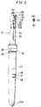
- the preferred embodiment of a wheel suspension system 20 includes a pair of left and right telescopic suspension assemblies 21 .
- Each of the suspension assemblies 21 has the identical construction to each other and comprises a sliding tube 22 rigidly secured on the steering bracket 15 , a generally cylindrical fork legs 23 , and a shock absorber assembly 24 disposed between the sliding tube 22 and the fork leg 23 .
- the fork leg 23 is formed through cold forging process and has a wheel axle hub section 23A at a lower reduced diameter section thereof.
- the wheel suspension system 20 includes a cross member holder 26 which is externally fitted onto the outer periphery of the fork leg 23 at a position immediately below an increased diameter section 25 .
- An essentially U-shaped cross member 27 is connected over the cross member holders 26 of the left and right fork legs 23 , which cross member 27 is provided a predetermined torsion strength.
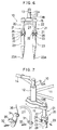
- the cross member holder 26 has an essentially annular ring shaped configuration shown in Fig. 3 .
- the cross member holder 26 is provided with a cross member mounting boss 28 and a pair of threaded bosses 29 for screw fastening engagement between the fork leg and the cross member holder at the desired orientation.
- the cross member 27 is mounted on the cross member holders 26 on the left and right fork legs 23 through mounting brackets 31 by means of fastening screws 32 .
- the cross member holder 26 is retained in place and prevented from axial displacement along the fork leg 23 by means of a retainer ring 26A fixed onto the outer periphery of the fork leg 23 at the position corresponding to the lower end of the cross member holder.
- the cross member holder 26 is further secured rigidly on the outer periphery of the fork leg 23 by means of fastening screws 33 engaging through the threaded bosses 29 .
- a brake lever 34 which forms a rim type brake system is secured on the cross member mounting boss 28 of one of the cross member holder 26 commonly with one of the mounting bracket 31 of the cross member 27 by means of the fastening screw 32 , as shown in Fig. 7 .
- the reference numeral 35 denotes a brake pad and 36 denotes a brake wire.
- the cross member holder 26 may be provided a brake lever mounting boss separately from the cross member mounting boss 28 so that the brake lever 34 may be mounted on this brake lever mounting boss independently of the cross member.
- the cross member 26 may be formed without the threaded bosses 29 , and provided a key recess 37 on the inner periphery thereof so that the key recess may receive a key projecting from the outer periphery of the fork leg 26 to restrict circumferential displacement thereof relative to the fork leg.
- the cross member holder 26 is retained in place by the combination of the effect of the retainer ring 26A mating the lower edge of the cross member holder and the key engagement between the key and key recess 37 .
- the suspension assembly 21 permits relative sliding and telescopic movement of the sliding tube 22 and the forK leg 23 , by a guide bushing 41 secured on the outer periphery of the sliding tube 22 in the vicinity of the lower end by means of fastening rings 41A and 41B , and a guide bushing 42 press fitted onto the inner periphery of the fork leg 26 in the vicinity of the upper end thereof.
- a seal spacer 43 Within a space defined between the increased diameter section 25 of the fork leg 23 and the outer periphery of the sliding tube 22 , a seal spacer 43 , an oil seal 44 , a stopper ring 45 and a dust seal 46 are mounted for establishing seal therebetween.
- a bumper rubber 49 is mounted on the upper end of the end plug member 48 .
- a rebounding rubber 51 is mounted on the upper inner periphery of the fork leg 23 and positioned immediately below the upper guide bushing 42 .
- the rebounding rubber 51 is active against a rebounding seat 53 which is fixed on the outer periphery of the sliding tube 22 at the intermediate position of the latter so that the rebounding seat 53 may abut against the upper guide bushing 42 via the rebounding rubber 51 at the end of the extension stroke of the suspension assembly 21 .
- the shock absorber assembly 24 comprises the piston body 61 bonded on the inner periphery of the sliding tube 22 at its lower end/
- a retaining ring 62 is put at the upper part of the bonding portion of the sliding tube and the piston body 61 .
- the piston body 61 demarcates an upper chamber 63A on the side of the sliding tube 22 and a lower chamber 63B on the side of the fork leg 23 , and has elongated hole-shaped compression stroke flow passages 64 and circular-shaped extension stroke flow passages 65 which enable to communicate the upper chamber 63A and the lower chamber 63B .
- the compression stroke flow passages 64 are arranged on the central side of the piston body and the extension stroke flow passages 65 on the outer peripheral side thereof, respectively.
- the upper chamber 63A is defined by an upper plug member 103 with an O-ring 102 mounted on the outer periphery thereof fixed at the upper end portion of the sliding tube 22 by means of a stop ring 101 , and the piston body 61 .
- a working fluid and air is filled in the upper chamber 63A so that the working fluid is positioned at the side of the piston body 61 to form a pneumatic pressure accumulator chamber thereabove.
- the lower chamber 63B is defined between the end plug member 48 and the piston body 61 .
- Working fluid is also filled in the lower chamber 63B .
- a slide valve type first valve 67 biased by a valve spring 66 in such a direction that the compression stroke flow passages 64 are shut, is arranged on the upper chamber side of the piston body 61 .
- pressure difference is caused between the upper and lower chambers 63A and 63B .
- the first valve 67 is shifted against the spring force to form a variable flow restrictive path to permit the working fluid to flow from the lower chamber 63B to the upper chamber 63A .
- Magnitude of fluid flow path area of the variable flow restrictive path defined by shifting of the first valve 67 is variable depending upon the magnitude of the pressure difference. Variable magnitude of damping force is generated depending upon magnitude of flow restriction at the variable flow restrictive path.
- a mounting bolt 68 is engaged to a threaded center bore 61A of the piston body 61 .
- a collar 71 In a clearance between a bolt head 68A and a nut 69 , a collar 71 , the piston body 61 , and a valve stopper 72 are arranged.
- the valve spring 66 is disposed between the spring seat 73 and the first valve 67 .
- the position of the valve seat 73 is determined by the bolt head 68A of the bolt 68 .
- the position of the valve seat 73 may also be adjusted by means of an adjuster 81 discussed later.
- a disc valve type second valve 74 which opens the extension stroke flow passages 65 due to the negative pressure of the lower chamber 63B when the sliding tube 22 and fork leg 23 are in the extension stroke, is arranged on the lower chamber 63B side of the piston body 61 .
- the second valve 74 is resiliently deformed to define a variable flow restrictive path between the piston body 61 to permit the working fluid to flow from the upper chamber 63A to the lower chamber 63B through the extension stroke flow passages 65 . Damping force against relative extension motion of the sliding tube 22 and the fork leg 23 is thus generated due to flow restriction by the variable flow restrictive fluid path.
- the path area of the variable flow restrictive path is variable depending upon magnitude of pressure difference.
- the pneumatic chamber in the upper chamber 63A is also effective for absorbing extension energy by permitting compression of the air therein.
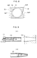
- the second valve 74 comprises, as shown in Fig. 5 , an inside annular portion 74A and an outside annular portion 74B , wherein the inside annular portion 74A and the outside annular portion 74B are connected by way of connecting portions 74C .
- the inside annular portion 74A is fixed on the lower end face of the piston body 61 by intermediary of the valve pressure member 72 by a nut 69
- the outside annular portion 74B is arranged so as to be capable of shutting the extension stroke flow passage 65 .
- the outside annular portion 74B can be displaced by the spring action of the connecting portions 74C so that the extension stroke flow passages 65 are shut.
- the elongated hole portion 74D corresponding to the compression stroke flow passages 64 are provided on both sides of the connecting portion 74C between the inside annular portion 74A and the outside annular portion 74B .
- the second valve 74 can be provided with sufficient rigidity for producing sufficiently large damping force against large magnitude of pressure difference during extension stroke motion.
- the second valve 74 can have sufficiently high response characteristics even for small magnitude of pressure difference by the flexibility provided at the connecting portion 74C .
- the piston body 61 has slits 75 and/or orifices 76 provided therein as throttle communication passages which constantly communicate the upper and lower chambers 63A and 63B .
- the slits 75 and the orifices 76 serve to communicate an area on the side of the extension side flow passages 65 that is never shut by the first valve 67 and an area on the side of the compression stroke flow passages 64 that is never shut by the second valve 74 .
- the shock absorber assembly 24 can generate damping force due to flow restriction through the slits 75 and the orifices 76 which constantly establish fluid communication between the upper and lower chambers 63A and 63B .
- an operation member 82 of the adjuster 81 is mounted though an O-ring 83 in rotatable fashion.
- the upper end portion of the operation member 82 extending from the sliding tube 22 is formed to have two flat faces for facilitating gripping and rotatingly operating the adjuster 81 .
- the lower end portion of the operating member 82 extending within the sliding tube 22 is formed into semi-circular cross section and coupled with the upper end of an adjusting pipe 84 .
- the coupling between the lower end of the operating member 82 and the upper end of the adjusting pipe 84 is established in such a manner than they are restricted in the relative displacement in the circumferential direction but permitted in the relative displacement in the axial direction.
- An adjusting nut 85 is rigidly secured on the lower end of the adjusting pipe 84 .
- the adjusting nut 85 is coupled with the bolt head 68A of the bolt 68 by thread engagement with the threaded portion on the bolt head.
- the lower end of the nut 85 can be extended downwardly across the axial position of the lower end face of the bolt head 68A to contact with the spring seat 73 .
- the adjuster 81 is permitted to rotate the adjusting nut 85 by the operation member 82 through the adjusting pipe 84 to threadingly shift the adjusting nut 85 relative to the bolt head 68A to shift the spring seat 73 up and down.
- the spring force of the valve spring 66 to be exerted on the first valve 67 can be adjusted. Therefore, the damping force to be generated during the compression stroke of the suspension system 20 can be adjusted.
- an air valve 86 is provided at the center of the operation member 82 of the adjuster 81 .
- the air valve 86 is operable for adjusting the air pressure in the pneumatic chamber of the upper chamber 63A .
- Fig. 8 is a plan view showing another embodiment of the cross member holder.
- the cross member holder 91 has, respectively, front and rear cross member mounting bosses 92F and 92R and two threaded bosses 93 .
- the cross member holder 91 is fixedly secured on the fork leg 23 by means of fastening screws 32 threadingly engaging with the threaded bosses 93 and firmly and tightly abutting onto the outer periphery of the fork leg 23 .
- the front cross member mounting bosses 92F of the cross member holders 91 secured on the left and right fork legs 23 are connected by a front cross member 94F .
- the rear cross member mounting bosses 92R of the cross member holders 91 are connected by a rear cross member 94R .
- the front and rear cross members 94F and 94R can be provided on both of the front and rear sides of the fork legs 23 . Accordingly, the rigidity of the suspension system 20 can be further increased.
- the fork leg 23 which is employed in the preferred embodiment of the suspension system according to the invention is produced through the process including the following steps (1) through (3) (see Figs. 9(A) and (B) ).
- the reducing forging for the lower portion of the fork leg 23 is performed for the tubular material using the end plug member 48 as a core metal.
- the fork leg 23 can be processed by reducing forging with maintaining the circularity at the portion of the lower chamber 63B where the sliding tube 22 slides. As a result, with a simple process, high precision and less expensive fork leg 23 can be obtained.
- the tubular member in the construction of the suspension system, in which the sliding tube and the fork leg are coupled in the telescopic fashion and the fork legs at both sides are connected to each other by the cross member for assuring sufficient rigidity, can be used as a material for the fork leg.
- the suspension system can provide shock absorbing effect even for the small undulation or projection on the road surface, and can generate damping force both in the compression and extension strokes. Therefore, the suspension system according to the present invention can assure a stable and comfortable ride.
- the present invention allows production of a fork leg through a simple process with high accuracy and low cost.
Landscapes
- Engineering & Computer Science (AREA)
- Mechanical Engineering (AREA)
- Axle Suspensions And Sidecars For Cycles (AREA)
- Fluid-Damping Devices (AREA)
- Steering Devices For Bicycles And Motorcycles (AREA)
Claims (4)
- Radaufhängungsanordnung für ein Fahrrad (10), umfassend:- ein linkes und ein rechtes verschiebbares Rohr (22), das an einer Lenkgabel (15) angebracht ist, die in einem vorderen Abschnitt eines Gestellrahmens (11) des Fahrrades (10) drehbar gehaltert ist;- einen linken und einen rechten Gabelarm (23), der ein Vorderrad haltert und ein entsprechendes der verschiebbaren Rohre (22) verschiebbar aufnimmt;- ein Paar von Stoßdämpferanordnungen (24), die jeweils zwischen zugehörigen verschiebbaren Rohren (22) und den Gabelarmen (23) angeordnet sind;- ein Paar von Querträgerhaltern (26, 91), die außen an Außenflächen der oberen Bereiche jedes der Gabelarme angebracht sind; und- einen Querträger (27), der eine vorbestimmte Drehfestigkeit liefert und mit den Querträgerhaltern (26, 91) verbunden ist;dadurch gekennzeichnet, daß- die Gabelarme (23) zylindrisch sind; und- das obere Ende jedes Gabelarms (23) einen vergrößerten Durchmesser, der eine rohrförmige Vergrößerung definiert, wobei der Übergang zwischen den beiden Durchmessern eine Schulter festlegt, wobei jeder Querträgerhalter (26, 91) in Anschlag an der Schulter angebracht ist, wobei der Raum zwischen dem Außenumfang jedes verschiebbaren Rohrs (22) und der Innenfläche der Erweiterung einen Dichtungsaufnahmeraum umgrenzt, und einen Haltering (26A) zur Aufnahme jedes Querträgerhalters an dem entsprechenden Gabelarm aufweist.
- Radaufhängungsanordnung nach Anspruch 1, bei der jeder der Querträgerhalter (26) mit vorderen und hinteren Montageabschnitten versehen ist, einer der Querträger (27) ein Vorderradquerträger ist, der vorgesehen ist, um eine Überspannung zwischen den vorderen Montageabschnitten der Querträgerhalter (26) an jedem der entsprechenden linken und rechten Gabelarme (23) vorzusehen, und der andere Querträger ein Hinterradquerträger ist, der vorgesehen ist, um eine Überspannung zwischen den hinteren Montageabschnitten der Querträgerhalter vorzusehen.
- Radaufhängungsanordnung nach Anspruch 1 oder 2, bei der jeder der Querträgerhalter an einer Außenfläche des Gabelarms mittels eines Eingriffs mit Vorsprung und Aussparung angebracht ist.
- Radaufhängungsanordnung für ein Fahrrad (10) nach einem beliebigen der Ansprüche 1 bis 3,- bei der jede Stoßdämpferanordnung umfaßt. einen Kolbenkörper (61), der eine obere Kammer (63A) an einer Seite des verschiebbaren Rohrs und eine untere Kammer (63B) an einer Seite des Gabelarms (23) umgrenzt;. ein erstes Ventil (67), das in einem Kolben vorgesehen ist, normalerweise vorgespannt zum Schließen eines Kompressionshubströmungskanals (64) für eine Fluidströmung von der unteren Kammer (63B) zu der oberen Kammer (63A);. ein zweites Ventil (74), das im Kolbenkörper vorgesehen ist, ansprechend auf eine Fluiddruckdifferenz zwischen der oberen und unteren Kammer während eines Ausdehnungshubs; und. einen strömungsbeschränkenden Verbindungskanal (65), der dauernd eine Fluidverbindung zwischen der oberen und der unteren Kammer in einer begrenzten Fluidströmungsrate bildet;- das erste Ventil (67) auf der Seite der oberen Kammer (63A) vorgesehen ist;- das zweite Ventil (74) auf der Seite der unteren Kammer (63B) vorgesehen ist und vorgesehen ist, um einen Ausdehnungshubströmungskanal (65) für eine Fluidströmung von der oberen Kammer (63A) zur unteren Kammer (63B) zu öffnen, weiter ein Scheibenventil umfaßt, das einen Innenringabschnitt (74A), einen Außenringabschnitt (74B) und einen Verbindungsabschnitt (74C) umfaßt, der sich zwischen dem Innen- und Außenringabschnitt erstreckt, wobei der Innenringabschnitt (74A) am Kolbenkörper (61) angebracht ist und der Außenringabschnitt (74B) sich an einer Position befindet, wobei er den Ausdehnungshubströmungskanal (65) verschließt; und- ein Federsitz (73) für eine Ventilfeder (66) des ersten Ventils (67) vorgesehen ist, welcher Federsitz (73) entlang einer axialen Position verstellbar ist, um eine auf das erste Ventil (67) auszuübende Federkraft mit einer Einstelleinrichtung (81) zu verändern, die von außen in das verschiebbare Rohr (22) auf drehbare Weise eingeführt wird, wobei der Kolbenkörper (61) am einem unteren Ende des verschiebbaren Rohrs (22) angebracht ist, enthaltend ein drehbar auf einem oberen Verschlußteil (103) drehbar gehaltertes Betätigungselement (82) und ein Einstellrohr (84).
Applications Claiming Priority (6)
| Application Number | Priority Date | Filing Date | Title |
|---|---|---|---|
| JP8044491A JPH04292289A (ja) | 1991-03-20 | 1991-03-20 | 自転車用車輪懸架装置のフォーク脚 |
| JP8044391A JPH04290626A (ja) | 1991-03-20 | 1991-03-20 | 自転車用車輪懸架装置 |
| JP80442/91 | 1991-03-20 | ||
| JP8044291A JPH04292286A (ja) | 1991-03-20 | 1991-03-20 | 自転車用車輪懸架装置 |
| JP80443/91 | 1991-03-20 | ||
| JP80444/91 | 1991-03-20 |
Publications (3)
| Publication Number | Publication Date |
|---|---|
| EP0508134A2 EP0508134A2 (de) | 1992-10-14 |
| EP0508134A3 EP0508134A3 (en) | 1993-01-07 |
| EP0508134B1 true EP0508134B1 (de) | 1995-08-23 |
Family
ID=27303299
Family Applications (1)
| Application Number | Title | Priority Date | Filing Date |
|---|---|---|---|
| EP92104170A Expired - Lifetime EP0508134B1 (de) | 1991-03-20 | 1992-03-11 | Aufhängungsanordnung für das Rad eines Zweirades |
Country Status (3)
| Country | Link |
|---|---|
| US (1) | US5328196A (de) |
| EP (1) | EP0508134B1 (de) |
| ES (1) | ES2075970T3 (de) |
Families Citing this family (43)
| Publication number | Priority date | Publication date | Assignee | Title |
|---|---|---|---|---|
| US5494302A (en) * | 1991-06-11 | 1996-02-27 | Cannondale Corporation | Suspension assembly for a vehicle |
| JP3381961B2 (ja) * | 1993-03-18 | 2003-03-04 | 株式会社ショーワ | 自転車用車輪懸架装置 |
| US5359910A (en) * | 1993-12-28 | 1994-11-01 | Bettis Corporation | Bicycle front fork shock absorbing mechanism |
| US5860665A (en) * | 1995-08-22 | 1999-01-19 | Keith O'Neal | Air powered shock absorber for front and rear forks of bicycles |
| DE19531844A1 (de) * | 1995-08-29 | 1997-03-06 | Fichtel & Sachs Ag | Stoßdämpfer für Fahrräder |
| US5829773A (en) * | 1996-01-19 | 1998-11-03 | Tenneco Automotive Inc. | Modular telescopic front fork assembly |
| JP4230568B2 (ja) * | 1998-07-24 | 2009-02-25 | 株式会社ショーワ | 油圧緩衝器のばねシート固定構造 |
| US6382373B1 (en) * | 1998-09-24 | 2002-05-07 | Tenneco Automotive Inc. | Frequency dependant damper |
| US6364075B1 (en) | 1998-09-24 | 2002-04-02 | Tenneco Automotive Inc. | Frequency dependent damper |
| WO2000063032A1 (fr) * | 1999-04-16 | 2000-10-26 | Compagnie Generale Des Etablissements Michelin-Michelin & Cie | Element formant articulation de suspension et ressort de torsion, en particulier pour vehicule |
| US6988427B2 (en) * | 2001-11-23 | 2006-01-24 | Shimano, Inc. | Seal assembly for a bicycle bottom bracket |
| JP2005308196A (ja) * | 2003-06-10 | 2005-11-04 | Showa Corp | 二輪車等のフロントフォーク |
| US6974143B2 (en) * | 2003-07-03 | 2005-12-13 | Showa Corporation | Hydraulic shock absorber for vehicle |
| JP5902967B2 (ja) * | 2012-03-07 | 2016-04-13 | Kyb株式会社 | 懸架装置 |
| US10526039B2 (en) | 2017-07-27 | 2020-01-07 | Trvstper, Inc. | Suspension assembly for a cycle |
| US10196106B1 (en) | 2017-07-27 | 2019-02-05 | Trvstper, Inc. | Suspension assembly for a cycle |
| US10308312B2 (en) | 2017-07-27 | 2019-06-04 | Trvstper, Inc. | Suspension assembly for a cycle |
| US10518836B2 (en) | 2017-07-27 | 2019-12-31 | Trvstper, Inc. | Suspension assembly for a cycle |
| US10300979B2 (en) | 2017-07-27 | 2019-05-28 | Trvstper, Inc. | Suspension assembly for a bicycle |
| US10526040B2 (en) | 2017-08-28 | 2020-01-07 | Trvstper, Inc. | Inline shock absorber with gas spring for a cycle wheel suspension assembly |
| US10549812B2 (en) | 2017-08-28 | 2020-02-04 | Trvstper, Inc. | Inline shock absorber with gas spring for a cycle wheel suspension assembly |
| US10549813B2 (en) | 2017-08-29 | 2020-02-04 | Trvstper, Inc. | Inline shock absorber with coil spring for a cycle wheel suspension assembly |
| US10518839B2 (en) | 2017-08-29 | 2019-12-31 | Trvstper, Inc. | Inline shock absorber with coil spring for a cycle wheel suspension assembly |
| JP7038536B2 (ja) * | 2017-12-12 | 2022-03-18 | 株式会社クボタ | 作業車両 |
| USD861542S1 (en) | 2018-02-08 | 2019-10-01 | Trvstper, Inc. | Cycle suspension assembly |
| USD880371S1 (en) | 2018-02-08 | 2020-04-07 | Trvstper, Inc. | Cycle suspension assembly |
| USD860062S1 (en) | 2018-02-08 | 2019-09-17 | Trvstper, Inc. | Cycle suspension assembly |
| USD859125S1 (en) | 2018-02-08 | 2019-09-10 | Trvstper, Inc. | Cycle suspension rebound knob |
| USD880372S1 (en) | 2018-02-08 | 2020-04-07 | Trvstper, Inc. | Cycle suspension assembly |
| USD880370S1 (en) | 2018-02-08 | 2020-04-07 | Trvstper, Inc. | Cycle suspension assembly |
| USD860061S1 (en) | 2018-02-08 | 2019-09-17 | Trvstper, Inc. | Cycle suspension assembly |
| USD880369S1 (en) | 2018-02-08 | 2020-04-07 | Trvstper, Inc. | Cycle suspension assembly |
| US20200079463A1 (en) | 2018-09-07 | 2020-03-12 | Trvstper, Inc. | Dual sided suspension assembly for a cycle wheel |
| US11084552B2 (en) | 2018-09-25 | 2021-08-10 | Specialized Bicycle Components, Inc. | Simplified gas spring setup for a trailing link cycle wheel suspension |
| US11230347B2 (en) | 2018-09-25 | 2022-01-25 | Specialized Bicycle Components, Inc. | Cycle wheel suspension assembly having gas pistons with unequal gas piston areas |
| US11230348B2 (en) | 2018-09-25 | 2022-01-25 | Specialized Bicycle Components, Inc. | Trailing link cycle wheel suspension assembly having gas pistons with unequal gas piston areas |
| US12319381B2 (en) | 2018-09-25 | 2025-06-03 | Specialized Bicycle Components, Inc. | Trailing link cycle wheel suspension assembly having gas pistons with unequal gas piston areas |
| US11230346B2 (en) | 2018-09-25 | 2022-01-25 | Specialized Bicycle Components Inc. | Cycle wheel suspension assembly having gas pistons with unequal gas piston areas |
| US11208172B2 (en) | 2018-10-05 | 2021-12-28 | Specialized Bicycle Components, Inc. | Suspension pivot assemblies having a retention feature |
| US11345432B2 (en) | 2018-10-12 | 2022-05-31 | Specialized Bicycle Components, Inc. | Suspension assembly for a cycle having a fork arm with dual opposing tapers |
| US11273887B2 (en) | 2018-10-16 | 2022-03-15 | Specialized Bicycle Components, Inc. | Cycle suspension with travel indicator |
| JP7202170B2 (ja) * | 2018-12-18 | 2023-01-11 | Kyb株式会社 | 流体圧緩衝器 |
| US11524744B2 (en) | 2019-04-09 | 2022-12-13 | Specialized Bicycle Components, Inc. | Cycle suspension with rotation sensor |
Citations (6)
| Publication number | Priority date | Publication date | Assignee | Title |
|---|---|---|---|---|
| US2329770A (en) * | 1941-04-28 | 1943-09-21 | Bundy Tubing Co | Closing ends of metal tubes |
| DE1260899B (de) * | 1962-01-11 | 1968-02-08 | Christian Marie Lucien Louis B | Federscheibenventil, insbesondere fuer Stossdaempferkolben |
| DE3720584A1 (de) * | 1986-07-25 | 1988-01-28 | Toyota Motor Co Ltd | Stossdaempfer |
| DE3820307C1 (en) * | 1988-06-15 | 1989-07-27 | Boge Ag, 5208 Eitorf, De | Piston for a hydraulic telescopic oscillation damper |
| JPH02231289A (ja) * | 1989-01-04 | 1990-09-13 | Rockshox Inc | 自転車の車輪懸架装置 |
| GB2234038A (en) * | 1989-06-15 | 1991-01-23 | Atsugi Unisia Corp | Variable damping force shock absorber |
Family Cites Families (11)
| Publication number | Priority date | Publication date | Assignee | Title |
|---|---|---|---|---|
| FR401115A (fr) * | 1909-03-22 | 1909-08-19 | Albert Keller Dorian | Frein réglable pour bicyclettes et motocyclettes |
| FR1054763A (fr) * | 1951-12-11 | 1954-02-12 | Fourche télescopique pour cycles, motocycles, etc. | |
| FR1051108A (fr) * | 1952-02-27 | 1954-01-13 | Dispositif stabilisateur pour motocyclettes et engins analogues | |
| FR1083394A (fr) * | 1953-09-16 | 1955-01-07 | Mecafor | Fourche élastique pour bicyclettes à moteur ou similaires |
| FR64890E (fr) * | 1953-11-30 | 1955-12-14 | Dispositif stabilisateur pour motocyclettes et engins analogues | |
| FR1103855A (fr) * | 1954-07-06 | 1955-11-08 | Fourche pneumatique destinée à la suspension élastique des cycles, cyclomoteurs, motocycles et véhicules similaires | |
| FR69875E (fr) * | 1955-10-05 | 1959-01-09 | J Souvignet Ets | Fourche élastique à éléments télescopiques pour bicyclettes à moteur ou similaires |
| US3470986A (en) * | 1967-06-29 | 1969-10-07 | Oldberg Mfg Co | Hydraulic shock absorber and flow control means therefor |
| US4203507A (en) * | 1977-04-29 | 1980-05-20 | Honda Giken Kogyo Kabushiki Kaisha | Shock absorber |
| DE2746879A1 (de) * | 1977-10-19 | 1979-04-26 | Lothar Schneier | Motorradgabel mit zwei federbeinen |
| JPS58211037A (ja) * | 1982-05-31 | 1983-12-08 | Nissan Motor Co Ltd | シヨツクアブソ−バ |
-
1992
- 1992-03-11 EP EP92104170A patent/EP0508134B1/de not_active Expired - Lifetime
- 1992-03-11 ES ES92104170T patent/ES2075970T3/es not_active Expired - Lifetime
- 1992-03-12 US US07/850,429 patent/US5328196A/en not_active Expired - Fee Related
Patent Citations (6)
| Publication number | Priority date | Publication date | Assignee | Title |
|---|---|---|---|---|
| US2329770A (en) * | 1941-04-28 | 1943-09-21 | Bundy Tubing Co | Closing ends of metal tubes |
| DE1260899B (de) * | 1962-01-11 | 1968-02-08 | Christian Marie Lucien Louis B | Federscheibenventil, insbesondere fuer Stossdaempferkolben |
| DE3720584A1 (de) * | 1986-07-25 | 1988-01-28 | Toyota Motor Co Ltd | Stossdaempfer |
| DE3820307C1 (en) * | 1988-06-15 | 1989-07-27 | Boge Ag, 5208 Eitorf, De | Piston for a hydraulic telescopic oscillation damper |
| JPH02231289A (ja) * | 1989-01-04 | 1990-09-13 | Rockshox Inc | 自転車の車輪懸架装置 |
| GB2234038A (en) * | 1989-06-15 | 1991-01-23 | Atsugi Unisia Corp | Variable damping force shock absorber |
Also Published As
| Publication number | Publication date |
|---|---|
| EP0508134A2 (de) | 1992-10-14 |
| US5328196A (en) | 1994-07-12 |
| EP0508134A3 (en) | 1993-01-07 |
| ES2075970T3 (es) | 1995-10-16 |
Similar Documents
| Publication | Publication Date | Title |
|---|---|---|
| EP0508134B1 (de) | Aufhängungsanordnung für das Rad eines Zweirades | |
| JP3381961B2 (ja) | 自転車用車輪懸架装置 | |
| US7425009B2 (en) | Front fork apparatus in two-wheeled vehicle or the like | |
| US6155541A (en) | Suspension assembly for a vehicle | |
| US7722069B2 (en) | Bicycle suspension system | |
| US4367882A (en) | Suspension apparatus | |
| US7195234B2 (en) | Adjustable gas spring suspension system | |
| JP3370130B2 (ja) | 自転車用前輪懸架装置 | |
| EP0927129A1 (de) | Fahrradaufhängungsvorrichtung | |
| EP1878646A2 (de) | Aufhängungssystem für ein Fahrrad | |
| US20110121525A1 (en) | Bicycle suspension-setting adjustor assembly | |
| US5346236A (en) | Suspension device for bicycle | |
| US4278266A (en) | Front fork construction for motorcycle | |
| US5397094A (en) | Saddle supporting device | |
| WO2024105913A1 (ja) | 車両用補強部材および車両 | |
| JPH1111374A (ja) | 自転車 | |
| US20050127587A1 (en) | Hydraulic shock absorbing apparatus of vehicle | |
| JPH07197975A (ja) | 車両用油圧緩衝器の減衰力発生装置 | |
| JPH04292286A (ja) | 自転車用車輪懸架装置 | |
| JP2002161937A (ja) | フロントフォークのばね荷重調整装置 | |
| WO2019014726A1 (en) | SUSPENSION DAMPING SYSTEM | |
| JP2572296Y2 (ja) | 自転車用車輪懸架装置 | |
| JPH04292289A (ja) | 自転車用車輪懸架装置のフォーク脚 | |
| JP4117098B2 (ja) | 二輪車の前輪支持用伸縮支柱 | |
| JPS63291785A (ja) | 自動二,三輪車用倒立型前フォークの加圧室構造 |
Legal Events
| Date | Code | Title | Description |
|---|---|---|---|
| PUAI | Public reference made under article 153(3) epc to a published international application that has entered the european phase |
Free format text: ORIGINAL CODE: 0009012 |
|
| 17P | Request for examination filed |
Effective date: 19920311 |
|
| AK | Designated contracting states |
Kind code of ref document: A2 Designated state(s): ES FR GB IT |
|
| PUAL | Search report despatched |
Free format text: ORIGINAL CODE: 0009013 |
|
| AK | Designated contracting states |
Kind code of ref document: A3 Designated state(s): ES FR GB IT |
|
| 17Q | First examination report despatched |
Effective date: 19931220 |
|
| RAP1 | Party data changed (applicant data changed or rights of an application transferred) |
Owner name: SHOWA CORPORATION |
|
| GRAA | (expected) grant |
Free format text: ORIGINAL CODE: 0009210 |
|
| ITF | It: translation for a ep patent filed | ||
| AK | Designated contracting states |
Kind code of ref document: B1 Designated state(s): ES FR GB IT |
|
| ET | Fr: translation filed | ||
| REG | Reference to a national code |
Ref country code: ES Ref legal event code: FG2A Ref document number: 2075970 Country of ref document: ES Kind code of ref document: T3 |
|
| PLBE | No opposition filed within time limit |
Free format text: ORIGINAL CODE: 0009261 |
|
| STAA | Information on the status of an ep patent application or granted ep patent |
Free format text: STATUS: NO OPPOSITION FILED WITHIN TIME LIMIT |
|
| 26N | No opposition filed | ||
| PGFP | Annual fee paid to national office [announced via postgrant information from national office to epo] |
Ref country code: FR Payment date: 20010220 Year of fee payment: 10 |
|
| PGFP | Annual fee paid to national office [announced via postgrant information from national office to epo] |
Ref country code: GB Payment date: 20010306 Year of fee payment: 10 |
|
| PGFP | Annual fee paid to national office [announced via postgrant information from national office to epo] |
Ref country code: ES Payment date: 20010313 Year of fee payment: 10 |
|
| REG | Reference to a national code |
Ref country code: GB Ref legal event code: IF02 |
|
| PG25 | Lapsed in a contracting state [announced via postgrant information from national office to epo] |
Ref country code: GB Free format text: LAPSE BECAUSE OF NON-PAYMENT OF DUE FEES Effective date: 20020311 |
|
| PG25 | Lapsed in a contracting state [announced via postgrant information from national office to epo] |
Ref country code: ES Free format text: LAPSE BECAUSE OF NON-PAYMENT OF DUE FEES Effective date: 20020312 |
|
| GBPC | Gb: european patent ceased through non-payment of renewal fee |
Effective date: 20020311 |
|
| PG25 | Lapsed in a contracting state [announced via postgrant information from national office to epo] |
Ref country code: FR Free format text: LAPSE BECAUSE OF NON-PAYMENT OF DUE FEES Effective date: 20021129 |
|
| REG | Reference to a national code |
Ref country code: FR Ref legal event code: ST |
|
| REG | Reference to a national code |
Ref country code: ES Ref legal event code: FD2A Effective date: 20030410 |
|
| PG25 | Lapsed in a contracting state [announced via postgrant information from national office to epo] |
Ref country code: IT Free format text: LAPSE BECAUSE OF NON-PAYMENT OF DUE FEES Effective date: 20050311 |