US11230347B2 - Cycle wheel suspension assembly having gas pistons with unequal gas piston areas - Google Patents

Cycle wheel suspension assembly having gas pistons with unequal gas piston areas Download PDF

Info

Publication number
US11230347B2
US11230347B2 US16/141,277 US201816141277A US11230347B2 US 11230347 B2 US11230347 B2 US 11230347B2 US 201816141277 A US201816141277 A US 201816141277A US 11230347 B2 US11230347 B2 US 11230347B2
Authority
US
United States
Prior art keywords
shock
spring
pivot
arm
link
Prior art date
Legal status (The legal status is an assumption and is not a legal conclusion. Google has not performed a legal analysis and makes no representation as to the accuracy of the status listed.)
Active, expires
Application number
US16/141,277
Other versions
US20200094909A1 (en
Inventor
David Weagle
Current Assignee (The listed assignees may be inaccurate. Google has not performed a legal analysis and makes no representation or warranty as to the accuracy of the list.)
Specialized Bicycle Components Holding Co Inc
Original Assignee
Specialized Bicycle Components Inc
Priority date (The priority date is an assumption and is not a legal conclusion. Google has not performed a legal analysis and makes no representation as to the accuracy of the date listed.)
Filing date
Publication date
Priority to US16/141,277 priority Critical patent/US11230347B2/en
Application filed by Specialized Bicycle Components Inc filed Critical Specialized Bicycle Components Inc
Priority to US16/159,069 priority patent/US11230346B2/en
Assigned to TRVSTPER, INC. reassignment TRVSTPER, INC. ASSIGNMENT OF ASSIGNORS INTEREST (SEE DOCUMENT FOR DETAILS). Assignors: WEAGLE, DAVID
Priority to PCT/US2019/052819 priority patent/WO2020068894A1/en
Priority to EP19784176.0A priority patent/EP3856624B1/en
Publication of US20200094909A1 publication Critical patent/US20200094909A1/en
Assigned to SPECIALIZED BICYCLE COMPONENTS, INC. reassignment SPECIALIZED BICYCLE COMPONENTS, INC. ASSIGNMENT OF ASSIGNORS INTEREST (SEE DOCUMENT FOR DETAILS). Assignors: TRVSTPER, INC.
Priority to US17/581,772 priority patent/US20220204123A1/en
Publication of US11230347B2 publication Critical patent/US11230347B2/en
Application granted granted Critical
Active legal-status Critical Current
Adjusted expiration legal-status Critical

Links

Images

Classifications

    • BPERFORMING OPERATIONS; TRANSPORTING
    • B62LAND VEHICLES FOR TRAVELLING OTHERWISE THAN ON RAILS
    • B62KCYCLES; CYCLE FRAMES; CYCLE STEERING DEVICES; RIDER-OPERATED TERMINAL CONTROLS SPECIALLY ADAPTED FOR CYCLES; CYCLE AXLE SUSPENSIONS; CYCLE SIDE-CARS, FORECARS, OR THE LIKE
    • B62K25/00Axle suspensions
    • B62K25/04Axle suspensions for mounting axles resiliently on cycle frame or fork
    • B62K25/06Axle suspensions for mounting axles resiliently on cycle frame or fork with telescopic fork, e.g. including auxiliary rocking arms
    • B62K25/08Axle suspensions for mounting axles resiliently on cycle frame or fork with telescopic fork, e.g. including auxiliary rocking arms for front wheel
    • BPERFORMING OPERATIONS; TRANSPORTING
    • B62LAND VEHICLES FOR TRAVELLING OTHERWISE THAN ON RAILS
    • B62KCYCLES; CYCLE FRAMES; CYCLE STEERING DEVICES; RIDER-OPERATED TERMINAL CONTROLS SPECIALLY ADAPTED FOR CYCLES; CYCLE AXLE SUSPENSIONS; CYCLE SIDE-CARS, FORECARS, OR THE LIKE
    • B62K25/00Axle suspensions
    • B62K25/04Axle suspensions for mounting axles resiliently on cycle frame or fork
    • B62K25/12Axle suspensions for mounting axles resiliently on cycle frame or fork with rocking arm pivoted on each fork leg
    • B62K25/22Axle suspensions for mounting axles resiliently on cycle frame or fork with rocking arm pivoted on each fork leg with more than one arm on each fork leg
    • B62K25/24Axle suspensions for mounting axles resiliently on cycle frame or fork with rocking arm pivoted on each fork leg with more than one arm on each fork leg for front wheel
    • BPERFORMING OPERATIONS; TRANSPORTING
    • B62LAND VEHICLES FOR TRAVELLING OTHERWISE THAN ON RAILS
    • B62KCYCLES; CYCLE FRAMES; CYCLE STEERING DEVICES; RIDER-OPERATED TERMINAL CONTROLS SPECIALLY ADAPTED FOR CYCLES; CYCLE AXLE SUSPENSIONS; CYCLE SIDE-CARS, FORECARS, OR THE LIKE
    • B62K21/00Steering devices
    • B62K21/02Front wheel forks or equivalent, e.g. single tine

Landscapes

  • Engineering & Computer Science (AREA)
  • Mechanical Engineering (AREA)
  • Vehicle Body Suspensions (AREA)

Abstract

A suspension assembly for a cycle having improved stability includes a steering fork having a first arm and a second arm, each of the first arm and the second arm having a fixed pivot and a shock pivot, the space between the first arm and the second arm defining a wheel opening. A shock link has a shock link fixed pivot and a shock link floating pivot. A shock absorber has a shock gas spring comprising a shock spring body a shock gas piston having a first gas piston area, a spring unit has a spring gas spring comprising a spring body and a spring gas piston having a second gas piston area. The first gas piston area is not equal to the second gas piston area.

Description

FIELD OF THE INVENTION
The disclosure is generally directed to wheel suspension assemblies for cycles, and more specifically directed to wheel suspension assemblies for cycles that improve stability and that have a shock absorber including a first gas spring on a first arm of a steering fork, and a spring unit including a second gas spring on a second arm of the steering fork, the first and second gas springs each including a gas piston, and a gas piston area of the first gas spring is unequal to the gas piston area of the second gas spring.
BACKGROUND
Recently, telescopic front suspension forks have dominated suspension systems for two-wheeled vehicles. A telescopic fork includes sliding stanchions connected in a steerable manner to a cycle frame, the sliding stanchions forming a telescoping mechanism for shock absorption during riding over rough terrain. Sliding stanchions require very tight manufacturing tolerances, so expensive round centerless ground stanchions are almost always used in high performance telescopic forks. Outer surfaces of the stanchion typically slide against bushings to allow for compliance, and in many designs, the inner surfaces of the stanchions slide against a damper or air spring piston to absorb shocks.
Front suspension for a cycle is subject to large bending forces fore and aft and less significant lateral forces. The round stanchions in a telescopic fork must be sized to support the greatest loads, in the fore/aft direction. This requires the use of relatively large diameter stanchions. The larger the stanchions, the greater the area of the supporting bushings and sliding surfaces. Because of the stacked layout, multiple redundant sliding surfaces must be used to seal in oil and air, as well as provide ample structural support.
Because telescopic forks have relatively large stanchions, and relatively large sliding surfaces and seals, large breakaway friction in the system (known as stiction) is generated by these components. Stiction resists compression of the suspension in reaction to bumps, which is a drawback in a suspension product where the goal is to react to road or terrain conditions, for example by deflecting in response to ground conditions, and/or absorbing impact from bumps. Additionally, as the telescopic fork is loaded in the fore/aft direction (usually on impact or braking), the bushings bind, resulting in even greater stiction at the exact moment when a rider needs the most compliance.
The higher the fore/aft load on the telescopic fork, the less effective the telescopic fork is at absorbing bumps. Most modern telescopic forks for cycles and motorcycles exhibit around 130 Newtons of stiction at their best, and thousands of Newtons of stiction when exposed to fore/aft loads.
Additionally, in the telescopic fork, mechanical trail is constrained by steering axis (head tube) angle and fork offset, a term for the perpendicular distance between the wheel rotation axis and the steering axis. Another problem with telescopic fork architecture is that when they are installed, mechanical trail reduces as the suspension is compressed, which reduces stability. When mechanical trail reduces, as the suspension compresses, less torque is required to steer the front wheel, causing a feeling of instability. This instability is a flaw in the telescopic fork. However, because most riders of 2-wheeled vehicles grew up only riding telescopic forks, they only know this feeling and nothing else. Thus, the inherent instability of a telescopic fork is the accepted normal.
Another drawback of the telescopic fork is a lack of leverage ratio. Telescopic forks compress in a linear fashion in response to bumps. The wheel, spring, and/or damper all move together at the same rate because they are directly attached to each other. Because the fork compresses linearly, and because the spring and/or damper are connected directly to the wheel, the leverage ratio of wheel to damper and spring travel is a constant 1:1.
Yet another drawback of telescopic forks is that angle of attack stability and stiction increase and oppose one another. In other words, as angle of attack stability increases, stiction also increases, which is undesirable. This problem is caused by the rearward angle of the fork stanchions. The less steeply (slacker) the fork stanchions are angled, the better the angle of attack is in relation to oncoming bumps. However, because the fork angle is largely governed by the steering axis (head tube) angle of the cycle's frame the sliding stanchions develop increased bushing load, and greater bending in fore and aft directions, resulting in increased stiction when slacker fork angles are used.
A further drawback of telescopic forks is called front suspension dive. When a rider applies the front brake, deceleration begins and the rider's weight transfers towards the front wheel, increasing load on the fork. As the telescopic front fork dives (or compresses) in response, the suspension stiffens, and traction reduces. This same load transfer phenomenon happens in most automobiles as well, but there is a distinction with a cycle telescopic fork in that the undesirable braking reaction in a cycle telescopic fork is made up of two components, load transfer and braking squat.
Load transfer, occurs when the rider's weight transfers forward during deceleration. That weight transfer causes an increased load on the front wheel, which compresses the front suspension.
Braking squat, which is the tendency of a front suspension to compress during braking, is measured in the front suspension kinematics, and can have a positive, negative, or zero value. This value is independent of load transfer, and can have an additive or subtractive effect to the amount of fork dive present during braking. A positive value (known as pro-dive) forcibly compresses the front suspension when the brakes are applied, cumulative to the already present force from load transfer. A zero value has no braking reaction at all; the front suspension is free to respond naturally to the effects of load transfer (for better or worse). A negative value (known as anti-dive) counteracts the front suspension's tendency to dive by balancing out the force of load transfer with a counteracting force.
With a telescopic fork, the only possible braking squat reaction is positive. Any time that the front brake is applied, the rider's weight transfers forward, and additionally, the positive pro-dive braking squat reaction forcibly compresses the suspension. Effectively, this fools the front suspension into compressing farther than needed, which reduces available travel for bumps, increases spring force, and reduces traction.
Angular wheel displacement relative to the ground during vertical suspension compression is an important characteristic to limit in a front suspension. A front wheel plane is constrained perpendicularly to the front axle, and symmetric to the front tire when measured in an unladen state. During vertical suspension compression, and in the case where the front wheel and front wheel plane are angularly displaced away from perpendicular with the ground and ground plane, the front wheel can exhibit a transient steering response or provide vague steering feedback for the rider, causing difficulty in control of the steering.
Telescopic forks are usually available in one of two layouts, called conventional and inverted.
A conventional layout typically has two fixed inner stanchions attached to a steering head, and an outer unitized lower leg assembly with a brace sometimes called an arch that connects two outer sliding members together and maintains relative common displacement between the two outer sliding members as the suspension compresses and extends. The arch is a structural member connecting the two outer sliding members and the arch typically extends around the outer circumference of the wheel. The conventional telescopic fork can use conventional and universal hubs, along with quick release style axles, which are less costly and more convenient for the user than custom designs or clamped axles.
Inverted telescopic fork layouts have the inner stanchions connected to the wheel axle, and two outer sliding members connected to a steering assembly. Because the two outer sliding members are only connected to each other by a wheel axle, this axle and the hub connection is used to maintain relative common displacement between the two outer sliding members as the suspension compresses and extends. Typically, the axle needs to be oversized in diameter and requires a secure connection, such as a clamp, to the two outer sliding members so that the axle is limited in both rotation and bending, to provide the stiffness required to limit angular wheel displacement. This oversized axle and clamping in turn requires oversized and heavy bearings and hub parts and requires the user to spend more time during assembly and disassembly of the front wheel from the inverted fork. The custom hubs required to work with the oversized axles are not typically universally mountable and are more costly than conventional hubs.
The inherent disadvantages of telescopic forks are not going away. In fact, as technology has improved in cycling, the speeds and loads that riders are putting into modern cycles, bicycles, motorcycles, and mountain cycles only make the challenges for the telescopic fork greater.
Linkage front suspensions have been attempted in the past as an alternative to telescopic forks, yet they have failed to overcome the inherent disadvantages of telescopic forks. Past linkage front suspensions have also failed to achieve prolonged market acceptance due to issues including difficult fitment to frames, limited access to adjustments, the exposure of critical parts to the weather, accelerated wear characteristics, difficulty of maintenance, undesirable ride and handling characteristics, and undesirable aesthetics.
Other linkage front suspensions have used shock absorbers including dampers and springs. Some shock absorbers have a damper that includes a volume of oil that is pressurized, for example by gas springs with a damper gas volume, by coil springs, by pre-compressed foam, by gas bags, or by other methods. In dampers using gas springs and coil springs to pressurize an oil volume, a piston commonly called an internal floating piston or IFP can be used to separate the damper gas volume or damper coil spring from the damper oil volume. In shock absorber designs using a gas spring, normal practice is to attach a gas spring piston to the damper body, such that the gas spring is situated outboard and concentric to the damper. This outboard and concentric arrangement of the gas spring with relation to the damper is referred to as a concentric shock absorber or shock absorber having a concentric configuration, and forces compromises in suspension design. These compromises can include a necessarily large overall diameter of the shock absorber which results in a large size and difficult fitment, or can require extremely small diameter damper pistons which impart detrimental damper performance, or can require extremely small area gas spring pistons which impart detrimental gas spring performance. Due to the necessarily large overall diameter of the concentric shock absorber, many other linkage front suspensions have been forced to mount the shock absorber external to the suspension, such that it is exposed to the weather. These suspensions using external shock absorbers have an unrefined and undesirable aesthetic appearance, along with the performance disadvantages that come with the external and concentric shock absorber arrangements.
Linkage front suspensions have the challenge of controlling angular wheel displacement relative to the fixed positions of the frame. Linkage front suspensions having linkage assemblies that are located on opposite sides of a wheel also have used a structural member otherwise known as an arch that connects the linkage assemblies by extending around a circumference of the wheel. This arch helps to maintain relative common displacement between the linkage members as the suspension compresses and extends. In some cases, this type of arch design requires the linkages to be placed close to the outside diameter of the wheel to use a shorter and stiffer arch, or alternatively use a very long, flexible, and heavy arch to connect all the way around the wheel. Locating linkage members close to the arch is desirable because this helps to give the links a mechanical advantage in controlling internal chassis forces with as lightweight of a structure as possible. Moving the linkages far away from the arch is undesirable because it presents an issue where angular wheel displacement and lateral wheel displacement can be magnified due to the amplification of unwanted linkage movement or flex. Other linkage front suspension designs have used springs on two sides of a wheel to attempt to distribute forces more evenly in the linkage and avoid the detrimental results of angular wheel displacement.
SUMMARY
In accordance with one exemplary aspect, a suspension assembly for a cycle includes a steering fork having a first arm and a second arm, each of which can include a first end and a second end. The first arm includes a shock absorber and the second arm includes a spring unit. The shock absorber has a damper and a shock gas spring. The shock gas spring includes a shock gas spring body and a shock gas piston, which has a first gas piston area. The shock absorber includes a first shock mount and a second shock mount, the first shock mount being connected to the first arm and the second shock mount being pivotably connected to a shock link. The spring unit includes a gas spring having a spring body and a spring gas piston, which has a second gas piston area. The spring unit also includes a first spring mount and a second spring mount, the second spring mount being pivotably connected to the spring link. The first gas piston is unequal to the second gas piston area.
BRIEF DESCRIPTION OF THE DRAWINGS
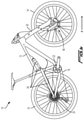
FIG. 1A is a side view of a cycle including a front wheel suspension assembly constructed according to the teachings of the disclosure.
FIG. 1B is a side view of an alternate embodiment of a cycle including a front wheel suspension assembly constructed according to the teachings of the disclosure, the cycle of FIG. 1B further including a rear wheel suspension assembly.
FIG. 2A is a close up side view of a first arm of the front wheel suspension assembly of FIG. 1.
FIG. 2B is a close up side view of a second arm of the front wheel suspension assembly of FIG. 1.
FIG. 3A is a side exploded view of the first arm and shock absorber of the front wheel suspension assembly of FIG. 2A.
FIG. 3B is a side exploded view of the second arm and spring unit of the front wheel suspension assembly of FIG. 2B.
FIG. 4A is a side cut-away view of a first embodiment of a shock absorber of the wheel suspension assembly of FIG. 2A.
FIG. 4B is a side cut-away view of a second embodiment of a shock absorber of the wheel suspension assembly of FIG. 2A.
FIG. 4C is a side cut-away view of a third embodiment of a shock absorber of the wheel suspension assembly of FIG. 2A.
FIG. 4D is a side cut-away view of a fourth embodiment of a shock absorber of the wheel suspension assembly of FIG. 2A.
FIG. 4E is a side cut-away view of a first embodiment of a gas spring of the wheel suspension assembly of FIG. 2B.
FIG. 5A is a side schematic view of the embodiment of a wheel suspension assembly of FIG. 2A, having the shock absorber of FIG. 4A or 4B.
FIG. 5B is a side schematic view of the embodiment of a wheel suspension assembly of FIG. 2A, having the shock absorber of FIG. 4C or 4D.
FIG. 5C is a side schematic view of the embodiment of a wheel suspension assembly of FIG. 2B, having the gas spring of FIG. 4E.
FIG. 6A is a perspective view of a first embodiment of a fixed or a floating pivot of the wheel suspension assembly of FIG. 2A.
FIG. 6B is a side perspective view and a side cross-sectional view of a second embodiment of a fixed or a floating pivot of the wheel suspension assembly of FIG. 2A.
FIG. 6C is an exploded view of a third embodiment of a fixed or a floating pivot of the wheel suspension assembly of FIG. 2A.
FIG. 6D is a side view of a fourth embodiment of a fixed or a floating pivot of the wheel suspension assembly of FIG. 2A.
FIG. 7A is a front cut-away view of the embodiment of the wheel suspension assembly of FIGS. 2A and 2B.
FIG. 7B is a front cut-away schematic view of the embodiment of the wheel suspension assembly of FIGS. 2A and 2B.
FIG. 8 is a side schematic view showing certain embodiments of wheel carriers of the suspension assembly.
DETAILED DESCRIPTION
The present invention is not to be limited in scope by the specific embodiments described below, which are intended as exemplary illustrations of individual aspects of the invention. Functionally equivalent methods and components fall within the scope of the invention. Indeed, various modifications of the invention, in addition to those shown and described herein, will become apparent to those skilled in the art from the foregoing description. Such modifications are intended to fall within the scope of the appended claims. Throughout this application, the singular includes the plural and the plural includes the singular, unless indicated otherwise. The words “formed,” “provided,” “disposed,” and “located,” individually or in combination, are used to denote relative positioning in the instant description. All cited publications, patents, and patent applications are herein incorporated by reference in their entirety.
One problem with suspension assemblies having springs with equal force outputs on each arm of a steering fork is that a force imbalance exists between the linkages on each side of the wheel, due to the fact that, during suspension compression, a damper force produced by a shock absorber on one arm of the steering fork is additive to the spring force on the shock absorber side of the steering fork. This additive force produces an undesirable force imbalance between the two arms of the steering fork. The disclosed suspension assemblies advantageously compensate for the inherent force imbalance between the two arms of the steering fork to produce equal overall force outputs between the two arms of the steering fork.
Turning now to FIG. 1A, a cycle 10 includes a frame 12, a front wheel 14, which in certain embodiments can include a rim and a tire, rotatably connected to a fork 30, and a rear wheel 16 rotatably connected to the frame 12. The rear wheel 16 is drivable by a drive mechanism, such as a chain 18 connected to a wheel sprocket 20 and to a chainring 22, so that driving force may be imparted to the rear wheel 16. The fork 30, allows the front wheel 14 to deflect relative to the frame 12 in response to ground conditions as a rider rides the cycle, to improve handling and control during riding. To improve handling characteristics, the fork 30 and the front wheel 14 are operatively connected to a suspension assembly or linkage 46. The frame 12 may optionally include a rear wheel suspension assembly (not shown in FIG. 1A), which may allow the rear wheel 16 to deflect in response to ground conditions as a rider rides the cycle, to improve handling and control during riding.
Turning now to FIG. 1B, a cycle 10 includes a frame 12, a front wheel 14, which in certain embodiments can include a rim and a tire, rotatably connected to a fork 30, and a rear wheel 16 rotatably connected to the frame 12. The fork 30 and the front wheel 14 are operatively connected to a suspension assembly or linkage 46. The rear wheel 16 is drivable by a drive mechanism, such as a chain 18 connected to a wheel sprocket 20 and to a chainring 22, so that driving force may be imparted to the rear wheel 16. The fork 30, allows the front wheel 14 to deflect relative to the frame 12 in response to ground conditions as a rider rides the cycle, to improve handling and control during riding. The frame 12 includes a rear wheel suspension assembly 24, which may allow the rear wheel 16 to deflect relative to the frame 12 in response to ground conditions as a rider rides the cycle, to improve handling and control during riding.
As illustrated in FIGS. 2-4, 7A, and 7B the fork 30 includes a first arm 32 and a second arm 33, each of which are operatively connected to a steering shaft 34. In the disclosed embodiment, the suspension assembly 46 includes a shock absorber 44 connected to the first arm 32 and a spring unit 48 connected to the second arm 33.
The steering shaft 34 includes a steering axis S that is formed by a central axis of the steering shaft 34. The first arm 32 has a first end 36 a second end 38, the first arm 32 including a first arm fixed pivot 40 and a first arm shock pivot 42. Similarly, the second arm 33 has a first end 37 and a second end 39, the second arm 33 including a second arm fixed pivot 140 and a second arm spring pivot 142.
The first arm shock pivot 42 operably connects a suspension device, such as the shock absorber 44 to the first arm 32. For example, the first arm shock pivot 42 allows relative motion, in this case rotation, between the shock absorber 44 and the first arm 32. In other embodiments, the first arm shock pivot 42 may allow other types of relative motion, such as flexure or translation, between the shock absorber 44 and the first arm 32. The first arm fixed pivot 40 pivotably connects one element of the linkage 46, as discussed further below, to the first arm 32.
Similarly, the second arm spring pivot 142 operably connects a suspension device, such as the spring unit 48 to the second arm 33. For example, the second arm spring pivot 142 allows relative motion, in this case rotation, between the spring unit 48 and the second arm 33. In other embodiments, the second arm spring pivot 142 may allow other types of relative motion, such as flexure or translation, between the spring unit 48 and the second arm 33. The second arm fixed pivot 140 pivotably connects one element of the linkage 46, as discussed further below, to the second arm 33.
A shock link 50 is pivotably connected to the first arm fixed pivot 40. The shock link 50 includes a shock link fixed pivot 52 and a shock link floating pivot 54 spaced apart from one another along a length of the shock link 50. The shock link 50 is pivotably connected to the first arm fixed pivot 40 at the shock link fixed pivot 52 such that the shock link 50 is rotatable about the shock link fixed pivot 52 and the shock link fixed pivot 52 remains in a fixed location relative to the first arm 32, while the shock link floating pivot 54 is movable relative to the first arm 32. In one embodiment, the shock link fixed pivot 52 and the first arm fixed pivot 40 are concentric and share a common axis of rotation.
Similarly, a spring link 150 is pivotably connected to the second arm fixed pivot 140. The spring link 150 includes a spring link fixed pivot 152 and a spring link floating pivot 154 spaced apart from one another along a length of the spring link 150. The spring link 150 is pivotably connected to the second arm fixed pivot 140 at the spring link fixed pivot 152 such that the spring link 150 is rotatable about the spring link fixed pivot 152 and the spring link fixed pivot 152 remains in a fixed location relative to the second arm 33, while the spring link floating pivot 154 is movable relative to the second arm 33. In one embodiment, the spring link fixed pivot 152 and the second arm fixed pivot 140 are concentric and share a common axis of rotation.
A pivot, as used herein, includes any connection structure that may be used to operatively connect one element to another element, and that allows relative movement between the connected elements. An operative connection may allow for one component to move in relation to another while constraining movement in one or more degrees of freedom. For example, the one degree of freedom may be pivoting about an axis. In one embodiment, a pivot may be formed from a journal or through hole in one component and an axle in another component. In other examples, pivots may include ball and socket joints. Yet other examples of pivots include, but are not limited to singular embodiments and combinations of, compliant mounts, sandwich style mounts, post mounts, bushings, bearings, ball bearings, plain bearings, flexible couplings, flexure pivots, journals, holes, pins, bolts, and other fasteners. Also, as used herein, a fixed pivot is defined as a pivotable structure that does not change position relative to the first arm 32 or to the second arm 33. As used herein, a floating pivot is defined as a pivot that is movable (or changes position) relative to another element, for example movable relative to first arm 32 or to the second arm 33.
As illustrated in FIGS. 2A and 2B, for example, the suspension assembly or linkage 46 is configured in a trailing orientation. A trailing orientation is defined herein as a linkage that includes a fixed pivot that is forward of the corresponding floating pivot when the cycle is traveling in the forward direction of travel as represented by arrow A in FIGS. 1A, 1B, 2A, and 2B. In other words, the floating pivot trails the fixed pivot when the cycle is traveling in the forward direction of travel A. For example, in the illustrated embodiment, the shock link fixed pivot 52 is forward of the shock link floating pivot 54. In other embodiments, the suspension assembly or linkage may be configured in a leading orientation, which includes a fixed pivot that is rearward of the corresponding floating pivot when the cycle is traveling in the forward direction.
The disclosed suspension assembly or linkage 46 is also characterized as a multi-bar linkage. A multi-bar linkage is defined herein as a linkage in which any part of the front wheel 14 is directly connected a link that is not directly connected to the fork 30. In the illustrated embodiment of FIGS. 1A and 2A, the front wheel is directly connected to the wheel carrier 62, which is not directly connected to the fork 30.
The shock absorber 44 includes a first shock mount 56 and a second shock mount 58, the first shock mount 56 being pivotably connected to the first arm shock pivot 42, the second shock mount 58 being pivotably connected to a shock connection pivot 60 located between the shock link fixed pivot 52 and the shock link floating pivot 54 along a length of the shock link 50. As illustrated in FIG. 4A, the shock absorber 44 also includes a shock gas spring 92 having a shock spring body 88, a damper 94 having a damper body 89, an inshaft 80, an outshaft 90, a damper piston 83, a shock gas piston 81, a first gas piston area 110, and a shaft seal 85. In the art, a damper may also be referred to as a dashpot and a gas spring may also be referred to as a mechanical spring. Furthermore, the outshaft 90 and the inshaft 80 may be integral elements (e.g., different sections of a common rod or stem), or the inshaft 80 and the outshaft 90 may be separate, but connected elements that share a common longitudinal axis. The first shock mount 56 can be located at any point along the length of the shock spring body 88 or along the length of the damper body 84. For example, the first shock mount 56 can be located closer to the inshaft 80 than to a first end 87 of the shock spring body 88. The first shock mount 56 can comprise various types of pivot designs and layouts, such as through bolt pivots, trunnion mounts, devises, or other types of pivots. The second shock mount 58 can be located at any point along the length of the inshaft 80. For example, the second shock mount 58 can be located closer to the damper 94 than a terminal second end 97 of the inshaft 80. The second shock mount 58 can comprise various types of pivot designs and layouts, such as through bolt pivots, trunnion mounts, devises, or other types of pivots. Although not shown by way of illustration, those skilled in the art would understand that the shock absorber 44 can be flipped longitudinally so that, in other embodiments, the first shock mount 56 is attached to the shock link 50 and/or the second shock mount 58 attached to the first arm 32. Shock absorber 44 mounting is not limited to the first shock mount 56 being attached to the first arm 32 and the second shock mount 58 being attached to the shock link 50 as illustrated in the accompanying figures.
The spring unit 48 includes a first spring mount 57 and a second spring mount 59, the first spring mount 57 being pivotably connected to the second arm spring pivot 142, the second spring mount 59 being pivotably connected to a spring connection pivot 160 located between the spring link fixed pivot 152 and the spring link floating pivot 154 along a length of the spring link 150. The spring unit 48 can also include a spring gas spring 192 having a spring body 188, an inshaft 180, a spring gas piston 181, a second gas piston area 111, a gas piston seal 191, and a shaft seal 185. In the art, a gas spring may also be referred to as a mechanical spring. The first spring mount 57 can be located at any point along the length of the spring body 188. For example, the first spring mount 57 can be located closer to the inshaft 180 than a terminal first end 187 of the spring body 188. The first spring mount 57 can comprise various types of pivot designs and layouts, such as through bolt pivots, trunnion mounts, clevises, or other types of pivots. The second spring mount 59 can be located at any point along the length of the inshaft 180. For example, the second spring mount 59 can be located closer to the spring body 188 than a terminal second end 197 of the inshaft 180. The second spring mount 59 can comprise various types of pivot designs and layouts, such as through bolt pivots, trunnion mounts, clevises, or other types of pivots. Although not shown by way of illustration, those skilled in the art would understand that the spring unit 48, in other embodiments, may be flipped longitudinally so that the first spring mount 57 is attached to the spring link 150 and/or the second spring mount 59 attached to the second arm 33. The spring unit 48 mounting is not limited to the first spring mount 57 being attached to the second arm 33 and the second spring mount 59 being attached to the spring link 150 as illustrated in the accompanying figures.
The inshafts 80, 180, and the outshaft 90 can comprise a singular component or plurality of components, and may be combined with other components. In some embodiments, the damper piston 83 may be connected to or include a portion or the entirety of the inshaft 80 or outshaft 90. In some embodiments, the damper piston 83 has a greater radial cross-sectional area than the inshaft 80 or the outshaft 90. The inshafts 80, 180 and the outshaft 90 can extend outward between and through a shaft seal 85, 185 to operably connect the shock gas spring 92 with the damper and/or to provide concurrent movement of any combination of the inshafts 80, 180, the outshaft 90, the shock gas piston 81, the spring gas piston 181, and the damper piston 83 during suspension compression and extension.
The damper piston mates to or includes a damper piston seal 93. In some embodiments, the damper piston seal 93 may comprise multiple, or combinations of, glide rings, wear bands, o-rings, X-rings, Q rings, quad rings, Teflon seals, cap seals, piston rings, solid pistons, T seals, V rings, U cups, urethane seals, PSQ seals, preloaded piston bands, or other type of bands/or seals. The damper piston seal 93 is intended to seal damping fluid between each side of the damper piston 83, while allowing axial movement of the damper piston 83 and therefore axial movement of the inshaft 80 and/or outshaft 90.
In certain embodiments, a gas spring has certain advantages over other types of springs and the shock gas spring 92 and the spring gas spring 192 both comprise a gas spring. The gas spring uses a pressurized gas such as air, nitrogen, or other gases to act on the area of a gas piston, for example the shock gas piston 81 or the spring gas piston 181, which results in an output of a force against the shock gas piston 81 or the spring gas piston 181. In certain embodiments, a user can change the gas pressure in either the shock gas spring 92 and/or in the spring gas spring 192, which changes the force output. In this manner, the user can tailor output force based on a preference or to meet the requirements of varying road conditions. In certain embodiments, the shock gas spring 92 and/or the spring gas spring 192 may comprise pressures that can act on both sides of the shock gas piston 81 and/or the spring gas piston 181. By varying the pressure of gas acting on one or both sides of the shock gas piston 81 and/or the spring gas piston 181, and/or by designing the shock gas piston 92 and/or the spring gas piston to have piston areas, the amount of force against the shock gas piston 81 and/or against the spring gas piston 181 may be varied. This variability can be a valuable tool for allowing the user to tailor output force based on their preference or to meet the requirements of varying road conditions. By varying the gas pressure acting against the first gas piston area 110, the force output against the shock gas piston 81 can be adjusted at various points in the damper displacement. By varying the gas pressure acting against the second gas piston area 111, the force output against the spring gas piston 181 can be adjusted.
The shock gas piston 81 and the spring gas piston 181 can be connected to or include a portion or the entirety of the inshaft 80, 180 or the outshaft 90. In preferred embodiments, the shock gas piston 81 and/or the spring gas piston 181 have a greater radial cross-sectional area than the inshaft 80, 180 or the outshaft 90. In certain other preferred embodiments, the shock gas piston 81 and/or the spring gas piston 181 have a greater radial cross-sectional area than the damper piston 83. The shock gas piston 81 and/or the spring gas piston 181 mates to or includes a gas piston seal 91, 191. In some embodiments, the gas piston seal 91, 191 may comprise; singular, multiple, or combinations of, glide rings, wear bands, o-rings, X-rings, Q rings, quad rings, Teflon seals, cap seals, piston rings, solid pistons, T seals, V rings, U cups, urethane seals, PSQ seals, preloaded piston bands, or other type of bands/or seals. The gas piston seal 91, 191 is intended to seal gas between sides of the shock gas piston 81 and/or the spring gas piston 181, while allowing axial movement of the shock gas piston 81 and/or the spring gas piston 181 and therefore axial movement of the inshaft 80, 180 and/or the outshaft 90.
The shock absorber 44 includes a shaft seal 85. The shaft seal 45 is used to seal damping fluid or gas inside the damper body 89 or the shock spring body 88 while allowing axial movement of an inshaft 80 and/or outshaft 90. The shaft seal 85 can be located at one end of the shock spring body 88, while sealing gas inside the shock spring body 88 and allowing axial movement of an inshaft 80 or outshaft 90. The shaft seal 85 can be located at one or more ends of a damper body 89, while sealing damping fluid inside the damper body 89 and allowing axial movement of an inshaft 80 or outshaft 90.
Similarly, the spring unit 48 includes a shaft seal 185. The shaft seal 185 is used to seal fluid or gas inside the spring body 188 while allowing axial movement of the inshaft 180. The shaft seal 185 can be located at one end of a spring body 188, while sealing gas inside the spring body 188 and allowing axial movement of an inshaft 180. The shaft seal 185 can be located at one or more ends of the spring body 188, while sealing damping fluid inside the spring body 188 and allowing axial movement of the inshaft 180.
A first wheel carrier 62 includes a wheel carrier first pivot 64 and a wheel carrier second pivot 66 spaced apart from one another along a length of the wheel carrier 62. Both the wheel carrier first pivot 64 and the wheel carrier second pivot 66 are floating pivots, as they both move relative to the first arm 32. A wheel mount 68 is adapted to be connected to a center of a wheel, for example the front wheel 14. In the disclosed embodiment, a center of the front wheel 14 is rotatably connected to the wheel mount 68. The wheel carrier first pivot 64 is pivotably connected to the shock link floating pivot 54 so that the wheel carrier second pivot 66 is pivotable about the wheel carrier first pivot 64 relative to the shock link floating pivot 54. The wheel carrier 62, in some embodiments, can include one or more brake mounts.
Similarly, a second wheel carrier 162 includes a wheel carrier first pivot 164 and a wheel carrier second pivot 166 spaced apart from one another along a length of the wheel carrier 162. Both the wheel carrier first pivot 164 and the wheel carrier second pivot 166 are floating pivots, as they both move relative to the second arm 33. A wheel mount 168 is adapted to be connected to a center of a wheel, for example the front wheel 14. In the disclosed embodiment, a center of the front wheel 14 is rotatably connected to the wheel mount 168. The wheel carrier first pivot 164 is pivotably connected to the spring link floating pivot 154 so that the wheel carrier second pivot 166 is pivotable about the wheel carrier first pivot 164 relative to the spring link floating pivot 154. The wheel carrier 162, in some embodiments, can include one or more brake mounts 163.
A first control link 70 includes a control link floating pivot 72 and a control link fixed pivot 74. The control link floating pivot 72 is pivotably connected to the wheel carrier second pivot 66, and the control link fixed pivot 74 is pivotably connected to the first arm control pivot 76 located on the first arm 32 such that the control link floating pivot 72 is pivotable about the control link fixed pivot 74, which remains in a fixed location relative to the first arm control pivot 76.
Similarly, a second control link 170 includes a control link floating pivot 172 and a control link fixed pivot 174. The control link floating pivot 172 is pivotably connected to the wheel carrier second pivot 166, and the control link fixed pivot 174 is pivotably connected to a second arm control pivot 176 located on the second arm 33 such that the control link floating pivot 172 is pivotable about the control link fixed pivot 174, which remains in a fixed location relative to the second arm control pivot 176.
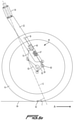
In some embodiments, the shock connection pivot 60 is closer to the shock link fixed pivot 52 than to the shock link floating pivot 54, as illustrated in FIG. 2 A. As a function of suspension compression and link movement, a perpendicular distance D between a central axis I of the inshaft 80 of the shock absorber 44 and a center of the shock link fixed pivot 52 varies as the shock absorber 44 is compressed and extended, as the shock absorber pivots about the first shock mount 56. A similar relationship may exist on the second arm 33 with respect to the spring link 50 and the inshaft 180. This pivoting and varying of the perpendicular distance D allows the leverage ratio and motion ratio to vary as the shock absorber 44 compresses and extends. As a function of suspension compression and link movement, a mechanical trail distance T varies as the shock absorber 44 compresses and extends. The mechanical trail distance T is defined as the perpendicular distance between the steering axis S and the contact point 82 of the front wheel 14 with the ground 84. More specifically, as the suspension compresses, beginning at a state of full extension, the mechanical trail distance T increases, thus increasing stability during compression. Compression is usually experienced during braking, cornering, and shock absorbing, all of which benefit from increased stability that results from the mechanical trail distance increase.
Mechanical trail (or “trail”, or “caster”) is an important metric relating to handling characteristics of two-wheeled cycles. Mechanical trail is a configuration in which the wheel is rotatably attached to a fork, which has a steering axis that is offset from the contact point of the wheel with the ground. When the steering axis is forward of the contact point, as in the case of a shopping cart, this configuration allows the caster wheel to follow the direction of cart travel. If the contact point moves forward of the steering axis (for example when reversing direction of a shopping cart), the directional control becomes unstable and the wheel spins around to the original position in which the contact point trails the steering axis. The friction between the ground and the wheel causes a self-righting torque that tends to force the wheel to trail the steering axis. The greater the distance between the contact point and perpendicular to the steering axis, the more torque is generated, and the greater the stability of the system. Similarly, the longer the distance between the cycle wheel contact point and perpendicular to the steering axis, the more torque is generated, and the greater the stability of the system. Conversely, the shorter the distance between the cycle wheel contact point and perpendicular to the steering axis, the less torque is generated, and the lower the stability of the system.
This caster effect is an important design characteristic in cycles. Generally, the caster effect describes the cycle rider's perception of stability resulting from the mechanical trail distance described above. If the wheel gets out of line, a self-aligning torque automatically causes the wheel to follow the steering axis again due to the orientation of the wheel ground contact point being behind the steering axis of the fork. As the contact point of the wheel with the ground is moved further behind the steering axis, self aligning torque increases. This increase in stability is referred to herein as the caster effect.
In the disclosed wheel suspension assembly, when the suspension is at a state of full extension, the steering axis of the fork 30 projects ahead of the contact point 82. As the suspension assembly moves towards a state of full compression, the steering axis S projects farther ahead of the contact point 82, which results in the stability increasing. This increased stability stands in contrast to known telescopic fork cycles, which experience reduced trail and thus reduced stability during compression.
Leverage ratios or motion ratios are important metrics relating to performance characteristics of some suspensions. In certain embodiments, a shock absorber can be compressed at a constant or variable rate as the suspension moves at a constant rate towards a state of full compression. As a wheel is compressed, incremental suspension compression distance measurements are taken. Incremental suspension compression distance is measured from the center of the wheel at the wheel rotation axis and parallel with the steering axis, starting from a state of full suspension extension, and moving towards a state of full suspension compression. These incremental measurements are called the incremental suspension compression distance. A shock absorber length can be changed by wheel link, and/or brake link, and/or control link movements as the suspension compresses. At each incremental suspension compression distance measurement, a shock absorber length measurement is taken. The relationship between incremental suspension compression distance change and shock absorber length change for correlating measurements of the suspension's compression is called leverage ratio or motion ratio. Leverage ratio and motion ratio are effectively equivalent but mathematically different methods of quantifying the effects of variable suspension compression distance versus shock compression distance. Overall leverage ratio is the average leverage ratio across the entire range of compression. Overall leverage ratio can be calculated by dividing the total suspension compression distance by the total shock absorber compression distance. Overall motion ratio is the average motion ratio across the entire range of compression. Overall motion ratio can be calculated by dividing the total shock absorber compression distance by the total suspension compression distance.
Generally, a suspended wheel has a compressible wheel suspension travel distance that features a beginning travel state where the suspension is completely uncompressed to a state where no further suspension extension can take place, and an end travel state where a suspension is completely compressed to a state where no further suspension compression can take place. At the beginning of the wheel suspension travel distance, when the suspension is in a completely uncompressed state, the shock absorber is in a state of least compression, and the suspension is easily compressed. As the suspended wheel moves compressively, force at the wheel changes in relation to shock absorber force multiplied by a leverage ratio. A leverage ratio is defined as the ratio of compressive wheel travel change divided by shock absorber measured length change over an identical and correlating given wheel travel distance. A motion ratio is defined as the ratio of shock absorber measured length change divided by compressive wheel travel change over an identical and correlating given wheel travel distance.
As stated above, in known telescopic forks no leverage ratio exists and, the leverage ratio is always equivalent to 1:1 due to the direct coupling of the wheel to the shock absorber.
A leverage ratio curve is a graphed quantifiable representation of leverage ratio versus wheel compression distance or percentage of full compression distance. Wheel compression distance, suspension compression, or wheel travel is measured from the center of the wheel at the wheel rotation axis and parallel with the steering axis, with the initial 0 percent measurement taken at full suspension extension with the vehicle unladen. As a suspension is compressed from a state of full extension to a state of full compression at a constant rate, measurements of shock absorber length are taken as the shortest distance between a first shock pivot and a second shock pivot at equal increments of suspension compression. When graphed as a curve on a Cartesian graph, leverage ratio is shown on the Y axis escalating from the x axis in a positive direction, and vertical wheel travel is shown on the X axis escalating from the Y axis in a positive direction.
A motion ratio curve is a graphed quantifiable representation of motion ratio versus wheel compression distance or percentage of full compression distance. Wheel compression distance, suspension compression, or wheel travel is measured from the center of the wheel at the wheel rotation axis and parallel with the steering axis, with the initial 0 percent measurement taken at full suspension extension with the vehicle unladen. As a suspension is compressed from a state of full extension to a state of full compression, measurements of shock absorber length are taken as the shortest distance between a first shock pivot and a second shock pivot at equal increments of suspension compression. When graphed as a curve on a Cartesian graph, motion ratio is shown on the Y axis escalating from the x axis in a positive direction, and vertical wheel travel is shown on the X axis escalating from the Y axis in a positive direction.
In certain embodiments, a leverage ratio or motion ratio curve can be broken down into three equal parts in relation to wheel compression distance or vertical wheel travel, a beginning ⅓ (third), a middle ⅓, and an end ⅓. In certain embodiments, a beginning ⅓ can comprise a positive slope, zero slope, and/or a negative slope. In certain embodiments, a middle ⅓ can comprise a positive slope, zero slope, and/or a negative slope. In certain embodiments, an end ⅓ can comprise a positive slope, zero slope, and/or a negative slope. Certain preferred leverage ratio embodiments can comprise a beginning ⅓ with a positive slope, a middle ⅓ with a less positive slope, and an end ⅓ with a more positive slope. Certain preferred leverage ratio embodiments can comprise a beginning ⅓ with a negative slope, a middle ⅓ with negative and zero slope, and an end ⅓ with a positive slope. Certain preferred leverage ratio embodiments can comprise a beginning ⅓ with a positive and negative slope, a middle ⅓ with negative and zero slope, and an end ⅓ with a positive slope. Certain preferred leverage ratio embodiments can comprise a beginning ⅓ with a positive and negative slope, a middle ⅓ with negative and zero slope, and an end ⅓ with a more negative slope. Certain preferred motion ratio embodiments can comprise a beginning ⅓ with a negative slope, a middle ⅓ with a less negative slope, and an end ⅓ with a more negative slope. Certain preferred motion ratio embodiments can comprise a beginning ⅓ with a positive slope, a middle ⅓ with positive and zero slope, and an end ⅓ with a negative slope. Certain preferred motion ratio embodiments can comprise a beginning ⅓ with a negative and positive slope, a middle ⅓ with positive and zero slope, and an end ⅓ with a negative slope. Certain preferred motion ratio embodiments can comprise a beginning ⅓ with a negative and positive slope, a middle ⅓ with positive and zero slope, and an end ⅓ with a more positive slope.
In contrast to telescopic suspensions, the disclosed wheel suspension assembly provides a greater than 1:1 overall leverage ratio between the shock absorber 44 and the shock link 50, due to the indirect coupling (through the linkage 46) of the wheel 14 and the shock absorber 44. In contrast to telescopic suspensions, the disclosed wheel suspension assembly provides a less than 1:1 overall motion ratio between the shock absorber 44 and the shock link 50, due to the indirect coupling (through the linkage 46) of the wheel 14 and the shock absorber 44. Additionally, because of the movement arcs of the various linkage elements, at any given point during compression, instantaneous leverage ratio and motion ratio can vary non-linearly.
The central axis I of the inshaft 80 of the shock absorber 44 is arranged to form an angle B of between 0° and 20° relative to a central axis F of the first arm 32, the central axis F of the first arm 32 being defined by a line formed between the first arm shock pivot 42 and the first arm fixed pivot 40. In other embodiments, the central axis I of the inshaft 80 of the shock absorber 44 forms an angle with the central axis F of the first arm 32 of between 0° and 15°. In other embodiments, the central axis I of the inshaft 80 of the shock absorber 44 forms an angle with the central axis F of the first arm 32 of between 0° and 30°. The angle B may vary within these ranges during compression and extension.
In some embodiments, the first arm 32 includes a hollow portion 86 and the shock absorber 44 is located at least partially within the hollow portion 86 of the first arm 32. Similarly, in other embodiments, the second arm 33 may include a hollow portion 186 and the spring unit 48 may be at least partially located within the hollow portion 186.
The shock link fixed pivot 52 is offset forward of the central axis I of the inshaft 80 of the shock absorber 44. In other words, the central axis I of the inshaft 80 of the shock absorber 44 is positioned between the shock link fixed pivot 52 and the shock link floating pivot 54 in a plane defined by the central axis I of the inshaft 80, the shock link fixed pivot 52 and the shock link floating pivot 54 (i.e., the plane defined by the view of FIGS. 2A and 2B).
A line between the wheel carrier first pivot 64 and the wheel carrier second pivot 66 defines a wheel carrier axis WC, and the wheel mount 68 is offset from the wheel carrier axis WC in a plane defined by the wheel carrier axis WC and the wheel mount 68 (i.e., the plane defined by the views of FIGS. 2A and 3B). In some embodiments, the wheel mount 68 is offset from the wheel carrier axis WC towards the first arm 32, for example the embodiment illustrated in FIGS. 2A and 3A. In other embodiments, the wheel mount 68 may be offset from the wheel carrier axis WC away from the first arm 32, for example in some of the wheel carrier 62 embodiments illustrated in FIG. 8.
In the embodiment of FIGS. 2A, 2B, 3A and 3B, the wheel mount 68, 168 is located aft of the shock link fixed pivot 52, or of the spring link fixed pivot 152, such that the central axis I of the inshaft 80, 180 of the shock absorber 44, or of the spring unit 48, is located between the wheel mount 68, 168 and the shock link fixed pivot 52, or the spring link fixed pivot 152, in a plane defined by the central axis I of the inshaft 80, 180, the wheel mount 68, 168 and the shock link fixed pivot 52, or the spring link fixed pivot 152 (i.e., the plane defined by the views of FIGS. 2A and 2B).
Turning now to FIG. 4A, in one embodiment, the shock absorber 44 may include an inline shock absorber having the damper body 89 and the shock spring body 88 sequentially arranged along a substantially common central axis.
The damper body 89 and the shock spring body 88 shall be considered to be inline and arranged sequentially along a substantially common central axis when a central axis of the shock spring body 88 and a central axis of the damper body 89 are offset from one another by a maximum of 100% of the outside diameter of an inshaft 80. In other embodiments, the damper body 89 and the shock spring body 88 are offset from one another by a maximum of 50% of the outside diameter of the inshaft 80. In other embodiments, the damper body 89 and the shock spring body 88 are offset from one another by a maximum of 33% of the outside diameter of the inshaft 80. In yet other embodiments, the damper body 89 and the shock spring body 88 are offset from one another by a maximum of 25% of the outside diameter of the inshaft 80. In a preferred embodiment, the damper body 89 and the shock spring body 88 share a common central axis.
The inshaft 80 extends from the damper body 89, and an outshaft 90 extends into the damper body 89 and into the shock spring body 88. The second shock mount 58 is formed at one end of the inshaft 80, and the inshaft 80 is pivotably connected to the shock connection pivot 60 by the second shock mount 58 such that the inshaft 80 and the outshaft 90 are compressible and extendable relative to the damper body 89 as the shock link 50 pivots about the shock link fixed pivot 52. In the embodiments of FIG. 4A, the damper body 89 is located between the shock spring body 88 and the second shock mount 58.
The shock absorber 44 includes the shock gas piston 81, and the first gas piston area 110. The shock absorber 44 includes the shaft seal 85. The shaft seal 85 is used to seal damping fluid or gas inside the damper body 89 and/or inside the shock spring body 88 while allowing axial movement of an inshaft 80 and/or outshaft 90. The shaft seal 85 can be located at one end of a shock spring body 88, while sealing gas inside the shock spring body 88 and allowing axial movement of an outshaft 90. The shaft seal 85 can be located at one end of the damper body 89, while sealing damping fluid inside the damper body 89 and allowing axial movement of the outshaft 90. The shaft seal 85 can be located at one end of the damper body 89, while sealing damping fluid inside the damper body 89 and allowing axial movement of the inshaft 80. The shock absorber 44 may include one or any combination of shaft seals 85 at the locations described above.
Turning now to FIG. 4B, in another embodiment, the shock absorber 44 may include an inline shock absorber having the damper body 89 and the shock spring body 88 sequentially arranged along a substantially common central axis. The shock absorber may further include the inshaft 80 that extends from the damper body 89, and the outshaft 90 that extends into the damper body 89 and into the shock spring body 88. The second shock mount 58 is formed at one end of the inshaft 80, and the inshaft 80 is pivotably connected to the shock connection pivot 60 by the second shock mount 58 such that the inshaft 80 and the outshaft 90 are compressible and extendable relative to the damper body 89 as the shock link 50 pivots about the shock link fixed pivot 52. In the embodiments of FIG. 4B, the damper body 89 is located between the shock spring body 88 and the second shock mount 58.
The shock absorber 44 includes the gas piston 88, and a first gas piston area 110. The shock absorber 44 includes the shaft seal 85. The shaft seal 85 is used to seal damping fluid or gas inside the damper body 89 and/or the shock spring body 88 while allowing axial movement of the inshaft 80 and/or the outshaft 90. The shaft seal 85 can be located at one end of the shock spring body 88, while sealing gas inside the shock spring body 88 and allowing axial movement of the outshaft 90. The shaft seal 85 can be located at one end of the shock spring body 88, while sealing gas inside the shock spring body 88, and additionally sealing damping fluid inside the damper body 89, and allowing axial movement of the outshaft 90. The shaft seal 85 can be located at one end of the damper body 89, while sealing damping fluid inside damper body 89 and allowing axial movement of the inshaft 80. The shock absorber 44 may include one or any combination of shaft seals 85 at the locations described above.
Turning now to FIG. 4C, in yet another embodiment, the shock absorber 44 may include an inline shock absorber having the shock spring body 88 and the damper body 89 sequentially arranged along a substantially common central axis. The shock absorber may further include the inshaft 80 that extends from the shock spring body 88, and the outshaft 90 that extends into the damper body 89 and into the shock spring body 88. The second shock mount 58 is formed at one end of the inshaft 80, and the inshaft 80 is pivotably connected to the shock connection pivot 60 by the second shock mount 58 such that the inshaft 80 and the outshaft 90 are compressible and extendable relative to the shock spring body 88 as the shock link 50 pivots about the shock link fixed pivot 52. The embodiment of FIG. 4C differs from the embodiment of FIG. 4A in that the shock spring body 88 is located between the damper body 89 and the second shock mount 58. In the embodiments of FIG. 4A, the damper body 89 was located between the shock spring body 88 and the second shock mount 58.
The shock absorber 44 includes the shock gas piston 81, and a first gas piston area 110. The shock absorber 44 includes the shaft seal 85. The shaft seal 85 is used to seal damping fluid or gas inside the shock spring body 88 and/or the damper body 89 while allowing axial movement of the inshaft 80 and/or the outshaft 90. The shaft seal 85 can be located at one end of the damper body 89, while sealing damping fluid or gas inside the damper body 89 and allowing axial movement of the outshaft 90. The shaft seal 85 can be located at one end of the shock spring body 88, while sealing gas inside the shock spring body 88 and allowing axial movement of an outshaft 90. The shaft seal 85 can be located at one end of the shock spring body 88, while sealing gas inside the shock spring body 88 and allowing axial movement of the inshaft 80.
Turning now to FIG. 4D, in yet another embodiment, the shock absorber 44 may include an inline shock absorber having the shock spring body 88 and the damper body 89 sequentially arranged along a substantially common central axis. The shock absorber may further include the inshaft 80 that extends from the shock spring body 88, and the outshaft 90 that extends into the damper body 89 and into the shock spring body 88. The second shock mount 58 is formed at one end of the inshaft 80, and the inshaft 80 is pivotably connected to the shock connection pivot 60 by the second shock mount 58 such that the inshaft 80 and the outshaft 90 are compressible and extendable relative to the shock spring body 88 as the shock link 50 pivots about the shock link fixed pivot 52. The embodiment of FIG. 4D differs from the embodiments of FIG. 4B in that the shock spring body 88 is located between the damper body 89 and the second shock mount 58. In the embodiments of FIG. 4B, the damper body 89 was located between the shock spring body 88 and the second shock mount 58.
The shock absorber 44 includes the shaft seal 85. The shaft seal 85 is used to seal damping fluid or gas inside the shock spring body 88 and/or the damper body 89 while allowing axial movement of the inshaft 80 and/or the outshaft 90. The shaft seal 85 can be located at one end of the damper body 89, while sealing damping fluid or gas inside the damper body 89 and allowing axial movement of the outshaft 90. The shaft seal 85 can be located at one end of the damper body 89, while sealing damping fluid or gas inside the damper body 89, and additionally sealing gas inside the shock spring body 88, and allowing axial movement of the outshaft 90. The shaft seal 85 can be located at one end of the shock spring body 88, while sealing gas inside shock spring body 88 and allowing axial movement of the inshaft 80.
Turning again to FIG. 4E, in one embodiment, the spring unit 48 may include the inshaft 180 that extends from the spring body 188. The first spring mount 57 is located in close proximity to the spring body 188. The second spring mount 59 is located in close proximity to one end of the inshaft 180, and the inshaft 180 is pivotably connected to the spring connection pivot 160 by the second spring mount 59 such that the inshaft 180 is compressible and extendable relative to the spring body 188 as the spring link 150 pivots about the spring link fixed pivot 152. The embodiment of FIG. 4E differs from the embodiments of FIGS. 4A,B,C, and D in that there is no outshaft 90 or damper 94.
The spring unit 48 includes the shaft seal 185. The shaft seal 185 is used to seal gas inside the spring body 188 while allowing axial movement of the inshaft 180. The shaft seal 185 can be located at one end of the spring body 188, while sealing gas inside spring body 188 and allowing axial movement of an inshaft 180.
FIG. 5A illustrates the wheel suspension assembly of FIG. 2A, with the shock absorber of FIG. 4A or 4B, in engineering symbols that distinguish the mechanical spring 47 (in this case a gas spring) and the dashpot 49 (or damper) of the shock absorber 44. The body of the dashpot 49 and one end of the mechanical spring 47 are connected to the first shock mount 56 to operably connect the gas spring with the damper to provide concurrent movement of spring and damper components during suspension compression and extension. The mechanical spring 47 is located above the dashpot 49 in an inline configuration in this embodiment.
FIG. 5B illustrates the wheel suspension assembly of FIG. 2A, with the shock absorber of FIG. 4C or 4D, in engineering symbols that distinguish the mechanical spring 47 and the dashpot 49 of the shock absorber 44. The body of the dashpot 49 and one end of the mechanical spring 47 are connected to the first shock mount 56 to operably connect a gas spring with a damper to provide concurrent movement of spring and damper components during suspension compression and extension. The dashpot 49 is located above the mechanical spring 47 in an inline configuration in this embodiment.
FIG. 5C illustrates the wheel suspension assembly of FIG. 2B, with the spring unit 48 of FIG. 4E, in engineering symbols that distinguish the mechanical spring 47 of the spring unit 48. The body of the mechanical spring 47 is connected to the first spring mount 57 to operably provide movement of spring components during suspension compression and extension.
Returning now to FIGS. 2A and 3A, the control link 70 is pivotably mounted to the first arm 32 at the first arm control pivot 76 that is located between the first arm fixed pivot 40 and the first arm shock pivot 42, along a length of the first arm 32.
Turning now to FIGS. 6A-6D, several embodiments of structures are illustrated that may be used as any of the pivots (fixed and/or floating), for example as the shock link fixed pivot 52 and/or the shock link floating pivot 54, described herein.
FIG. 6A illustrates a cardan pivot 100. The cardan pivot includes a first member 101 and a second member 102 that are pivotably connected to one another by yoke 105 which comprises a first pin 103 and a second pin 104. As a result, the first member 101 and the second member 102 may move relative to one another about an axis of the first pin 103 and/or about an axis of the second pin 104.
FIG. 6B illustrates a flexure pivot 200. The flexure pivot 200 includes a flexible portion 203 disposed between a first member 201 and a second member 202. In the illustrated embodiment, the first member 201, the second member 202, and the flexible portion 203 may be integrally formed. In other embodiments, the first member 201, the second member 202, and the flexible portion 203 may be separate elements that are connected to one another. In any event, the flexible portion 203 allows relative motion between the first member 201 and the second member 202 about the flexible portion 203. The flexible portion 203 is more flexible than the members 201 and 202, permitting localized flexure at the flexible portion 203. In the illustrated embodiment, the flexible portion 203 is formed by a thinner portion of the overall structure. The flexible portion 203 is thinned sufficiently to allow flexibility in the overall structure. In certain embodiments, the flexible portion 203 is shorter than 100 mm. In certain embodiments, the flexible portion 203 is shorter than 70 mm. In certain embodiments, the flexible portion 203 is shorter than 50 mm. In certain embodiments, the flexible portion 203 is shorter than 40 mm. In certain preferred embodiments, the flexible portion 203 is shorter than 30 mm. In certain other preferred embodiments, the flexible portion 203 is shorter than 25 mm.
FIG. 6C illustrates a bar pin pivot 300. The bar pin pivot includes a first bar arm 301 and a second bar arm 302 that are rotatably connected to a central hub 303. The central hub 303 allows the first bar arm 301 and the second bar arm 302 to rotate around a common axis.
FIG. 6D illustrates a post mount pivot 400. The post mount pivot 400 includes a mounting stem 401 that extends from a first shock member 402. The mounting stem 401 is connected to a structure 407 by a nut 404, one or more retainers 405, and one or more grommets 406. The first shock member 402 is allowed relative movement by displacement of the grommets 406, which allows the mounting stem 401 to move relative to a structure 407 in at least one degree of freedom.
FIG. 7A illustrates a certain embodiment of the wheel suspension assembly in a front view, where a space between the first arm 32 and the second arm 33 of the steering fork 30, in part, defines a wheel opening 61. The front wheel 14 moves within an envelope 15, during suspension compression, and extension. The wheel opening 61 allows clearance for the front wheel 14 so that the front wheel 14 does not contact the steering fork 30 during suspension compression, and extension. In this embodiment, the shock absorber 44 is shown positioned on the first arm 32, and the spring unit 48 is shown positioned on the second arm 33. In other embodiments, the shock absorber 44 and the spring unit 48 may be reversed with the shock absorber being positioned in the second arm 33 and the spring unit being positioned on the first arm 32. For clarity, although the first arm 32 is illustrated on the left side in the figures and the second arm 33 is illustrated on the right side in the figures, in other embodiments, the first arm 32 may be located on the right side, when viewed from the front and the second arm 33 may be located on the left side when viewed from the front in the forward direction of travel.
The shock link 50 (or the spring link 150) is pivotably connected to the first arm fixed pivot 40 or to the second arm fixed pivot 140 at the shock link fixed pivot 52, or at the spring link fixed pivot 152, such that the shock link 50 (or the spring link 150) is rotatable about a first pivot axis 53 a of the shock link fixed pivot 52 (or of the spring link fixed pivot 152) and the shock link fixed pivot 52 (or the spring link fixed pivot 152) remains in a fixed location relative to the first arm 32, or to the second arm 33, while the shock link 50 (or the spring link 150) is movable relative to the first arm 32, or to the second arm 33.
The shock absorber 44 includes the first shock mount 56 and the second shock mount 58, the first shock mount 56 being pivotably connected to the first arm 32 and rotatable about a second pivot axis 53 b. The second shock mount 58 is formed at one end of the inshaft 80, and the inshaft 80 is pivotably connected about a third pivot axis 53 c to the shock connection pivot 60 by the second shock mount 58 such that the inshaft 80 is compressible and extendable relative to the damper body 89 and shock spring body 88 as the shock link 50 pivots about the shock link fixed pivot 52. The shock absorber 44 includes the shock gas piston 81, and the first gas piston area 110.
The spring unit 48 includes the first spring mount 57 and the second spring mount 59, the first spring mount 57 being pivotably connected to the second arm 33 about a fourth pivot axis 53 d. The second the second spring mount 59 is formed at one end of the inshaft 180, and the inshaft 180 is pivotably connected about the third pivot axis 53 c to the spring connection pivot 160 by the second spring mount 59 such that the inshaft 180 is compressible and extendable relative to the spring body 188 as the spring link 150 pivots about the spring link fixed pivot 152. The spring unit 48 includes a spring gas piston 188, and the second gas piston area 111.
The first gas piston area 110 is unequal to the second gas piston area 111. In some embodiments, the second gas piston area 111 is larger than the first gas piston area 110. In some embodiments, the second gas piston 111 area is between 2% and 300% larger than the first gas piston area 110. In other embodiments, the second gas piston area 111 area is preferably between 15% and 100% larger than the first gas piston area 110, for example, between 15% and 40%, and even more preferably between 25% and 30% larger than the first gas piston area 110. The second gas piston area 111 being between 15% and 40% larger, particularly between 25% and 30% larger, than the first gas piston area 110 produces a user friendly rider experience and ease of pressurization of the shock gas spring 92 and the spring gas spring 192. One having ordinary skill in the art, upon reading the teachings of the disclosure, would be able to adjust relative sizes of the first gas piston area 110 and the second gas piston area 111 to compensate for any size damper.
FIG. 7B illustrates the wheel suspension assembly of FIG. 7A, in a front view, with the shock absorber of FIGS. 4A-D and the spring unit of FIG. 4E, in engineering symbols that distinguish the mechanical spring 47 and the dashpot 49 of the shock absorber 44 and the spring unit 48. The body of the dashpot 49 and one end of the mechanical spring 47 are connected to the first shock mount 56 to operably connect the shock gas spring with the damper to provide concurrent movement of spring and damper components during suspension compression and extension. The dashpot 49 is located below the mechanical spring 47 in an inline configuration in this embodiment, but the dashpot 49 could be located above or concentric to the mechanical spring 47 in other configurations.
The space between the first arm 32 and the second arm 33 of the steering fork 30, in part, defines the wheel opening 61. The front wheel 14 moves within the envelope 15, during suspension compression and extension. The wheel opening 61 allows clearance for the front wheel 14 so that the front wheel 14 does not contact the steering fork 30 during suspension compression and extension. In this embodiment, the shock absorber 44, which comprises the mechanical spring 47 and the dashpot 49, is positioned on the first arm 32, and the spring unit 48, comprises the mechanical spring 47, is positioned on the second arm 33. In other embodiments, the shock absorber 44 could be positioned on the second arm 33, and the spring unit 48 could be positioned on the first arm 32.
The shock link 50 is pivotably connected to the first arm fixed pivot 40 at the shock link fixed pivot 52 such that the shock link 50 is rotatable about the first pivot axis 53 a of the shock link fixed pivot 52 and the shock link fixed pivot 52 remains in a fixed location relative to the first arm 32, while the shock link 50 is movable relative to the first arm 32.
FIG. 8 illustrates in a side schematic view certain alternative embodiments of wheel carriers that may be used in the suspension assemblies of FIGS. 1-7. A first wheel carrier 62 is illustrated, and it should be understood that the features of the first wheel carrier 62 can be similar or equivalent to the features of the second wheel carrier 162 as illustrated in other figures herein. In the illustrated embodiments, the wheel mount 68 can be located at any point attached to the first wheel carrier 62. The wheel mount 68 can be located on either side of, or in-line with a line wheel carrier axis WC. The wheel mount 68 can be located between a wheel carrier first pivot 64 and a wheel carrier second pivot 66 or the wheel mount 68 can be located not between a wheel carrier first pivot 64 and a wheel carrier second pivot 66.
As used herein, a damper is a device that receives an input in shaft displacement, and resists shaft displacement. The resistance to shaft displacement can be measured as an output in force relative to the shaft displacement, velocity, and/or acceleration. A damper can output force that is variable to shaft displacement, velocity, and/or acceleration. A damper can include a pressurized oil volume which can be pressurized by a gas spring including a damper gas volume or other methods. A damper using a gas spring to pressurize an oil volume can include a gas piston called commonly called an internal floating piston or by the acronym “IFP” to separate the damper gas volume from the damper oil volume. In some dampers using a pressurized oil volume, the oil pressure acts on the area of a damper shaft, creating a force output at the damper shaft. A damper having a damper gas piston can be used in conjunction with a gas spring having its own gas piston.
In certain preferred embodiments, a spring or spring unit includes the spring gas spring 192, wherein the spring gas spring 192 exerts a force output in relation to shaft displacement.
In certain preferred embodiments, a shock absorber 44 includes the shock gas spring 92 and the damper 94, wherein the shock gas spring 92 and the damper 94 of the shock absorber 44 exert a combined force output.
The disclosed wheel suspension assemblies have a first gas piston area 110 and a second gas piston area 111 that are unequal to each other. In certain preferred embodiments, the first gas piston area 110 is less than the second gas piston area 111, which allows for a more equal force output between the shock absorber 44 and the spring unit 48, which helps to distribute forces more evenly in the linkage and avoid the detrimental results of angular wheel displacement.
The disclosed wheel suspension assemblies can be designed to be lighter in weight, lower in friction, more compliant, safer, and perform better than traditional wheel suspension assemblies.
The disclosed wheel suspension assemblies also reduce stiction and increase stability during braking, cornering, and shock absorption, when compared to traditional wheel suspension assemblies.
The disclosed wheel suspension assemblies are particularly well suited to E-bikes. E-bikes are heavier and faster than typical mountain bikes. They are usually piloted by less skilled and less fit riders, and require a stronger front suspension to handle normal riding conditions. E-bikes are difficult to build, requiring the challenging integration of motors and batteries into frame designs. In many cases, the electric parts are large and unsightly.
E-bikes are typically cost prohibitive to build as well, requiring special fittings to adapt motors and batteries. To integrate one center-drive motor, the additional cost to the manufacturer is about double the price of a common bicycle frame. That cost is multiplied and passed onto the consumer.
The beneficial caster effect described above with respect to the disclosed wheel suspension assemblies is an important improvement over traditional wheel suspension assemblies and reduces some of the drawbacks of E-bikes.
Additionally, because the disclosed wheel suspension assemblies are not constrained by round stanchions, the oval fork legs balance fore-aft and side to side compliance for ultimate traction. Combining superior chassis stiffness while eliminating stiction gives the disclosed wheel suspension assemblies a performance advantage over traditional wheel suspension assemblies.
While a two-wheeled bicycle is disclosed, the disclosed wheel assemblies are equally applicable to any cycle, such as motorcycle, unicycle, or tricycle vehicles. Furthermore, the disclosed wheel suspension assemblies are easily retrofittable to traditional cycles.

Claims (8)

What is claimed:
1. A suspension assembly for a cycle, the suspension assembly comprising:
a steering fork, the steering fork having a first arm and a second arm, each of the first arm and the second arm having a first end and a second end;
a shock absorber having a damper body and shock gas spring comprising a shock spring body and a shock gas piston having a first gas piston area, the shock spring body being sequentially arranged along a substantially common central axis with the damper body, the shock absorber including a first shock mount and a second shock mount, the first shock mount being connected to the first arm, the second shock mount being pivotably connected to a shock link, and the shock absorber being located on the first arm;
a spring unit, having a spring gas spring comprising a spring body and a spring gas piston having a second gas piston area, a first spring mount and a second spring mount, the first spring mount being connected to the second arm, the second spring mount being pivotably connected to a spring link, and the spring unit being substantially located on the second arm;
wherein the first gas piston area and the second gas piston area are unequal.
2. The suspension assembly of claim 1, further comprising:
a first arm fixed pivot, a first arm shock pivot, and a first arm control pivot, a space between the first arm and the second arm forming a wheel opening;
the shock link, the shock link having a shock link fixed pivot and a shock link floating pivot spaced apart from one another, the shock link being pivotably connected to the first arm fixed pivot at the shock link fixed pivot such that the shock link is rotatable about the shock link fixed pivot and the shock link fixed pivot remains in a fixed location relative to the first arm while the shock link floating pivot is movable relative to the first arm;
a wheel carrier, the wheel carrier having a wheel carrier first pivot and a wheel carrier second pivot spaced apart from one another along a length of the wheel carrier, and a wheel mount that is adapted to be connected to a wheel, the wheel carrier first pivot being pivotably connected to the shock link floating pivot so that the wheel carrier second pivot is rotatable about the wheel carrier first pivot relative to the shock link floating pivot; and
a control link, the control link including a control link floating pivot and a control link fixed pivot, the control link floating pivot being pivotably connected to the wheel carrier second pivot, and the control link fixed pivot being pivotably connected to the first arm control pivot such that the control link floating pivot is rotatable about the control link fixed pivot, which remains in a fixed location relative to the first arm control pivot.
3. The suspension assembly of claim 2, wherein the damper body is located between the shock spring body and the second shock mount along the common central axis.
4. The suspension assembly of claim 2, wherein the second gas piston area is larger than the first gas piston area.
5. The suspension assembly of claim 2, wherein the suspension assembly is a multi-link assembly.
6. The suspension assembly of claim 2, wherein the shock gas piston has a greater radial cross-sectional area than a damper piston.
7. The suspension assembly of claim 2, wherein the shock spring body is located between the damper body and the second shock mount along the common central axis.
8. The suspension assembly of claim 1, wherein the central axis of the shock spring body and a central axis of the damper body are arranged so that the central axis of the shock spring body and the central axis of the damper body are offset from one another by a maximum of 100% of the outside diameter of an inshaft of the inline shock absorber.
US16/141,277 2018-09-25 2018-09-25 Cycle wheel suspension assembly having gas pistons with unequal gas piston areas Active 2040-07-19 US11230347B2 (en)

Priority Applications (5)

Application Number Priority Date Filing Date Title
US16/141,277 US11230347B2 (en) 2018-09-25 2018-09-25 Cycle wheel suspension assembly having gas pistons with unequal gas piston areas
US16/159,069 US11230346B2 (en) 2018-09-25 2018-10-12 Cycle wheel suspension assembly having gas pistons with unequal gas piston areas
PCT/US2019/052819 WO2020068894A1 (en) 2018-09-25 2019-09-25 Cycle wheel suspension assembly having gas pistons with unequal gas piston areas
EP19784176.0A EP3856624B1 (en) 2018-09-25 2019-09-25 Cycle wheel suspension assembly having gas pistons with unequal gas piston areas
US17/581,772 US20220204123A1 (en) 2018-09-25 2022-01-21 Trailing link cycle wheel suspension assembly having gas pistons with unequal gas piston areas

Applications Claiming Priority (1)

Application Number Priority Date Filing Date Title
US16/141,277 US11230347B2 (en) 2018-09-25 2018-09-25 Cycle wheel suspension assembly having gas pistons with unequal gas piston areas

Related Parent Applications (1)

Application Number Title Priority Date Filing Date
US16/141,887 Continuation-In-Part US11230348B2 (en) 2018-09-25 2018-09-25 Trailing link cycle wheel suspension assembly having gas pistons with unequal gas piston areas

Related Child Applications (1)

Application Number Title Priority Date Filing Date
US16/159,069 Continuation-In-Part US11230346B2 (en) 2018-09-25 2018-10-12 Cycle wheel suspension assembly having gas pistons with unequal gas piston areas

Publications (2)

Publication Number Publication Date
US20200094909A1 US20200094909A1 (en) 2020-03-26
US11230347B2 true US11230347B2 (en) 2022-01-25

Family

ID=69884052

Family Applications (1)

Application Number Title Priority Date Filing Date
US16/141,277 Active 2040-07-19 US11230347B2 (en) 2018-09-25 2018-09-25 Cycle wheel suspension assembly having gas pistons with unequal gas piston areas

Country Status (1)

Country Link
US (1) US11230347B2 (en)

Cited By (3)

* Cited by examiner, † Cited by third party
Publication number Priority date Publication date Assignee Title
US11524744B2 (en) 2019-04-09 2022-12-13 Specialized Bicycle Components, Inc. Cycle suspension with rotation sensor
US11820457B2 (en) 2018-10-16 2023-11-21 Specialized Bicycle Components, Inc. Cycle suspension with travel indicator
US11945539B2 (en) 2018-09-07 2024-04-02 Specialized Bicycle Components, Inc. Dual sided suspension assembly for a cycle wheel

Families Citing this family (6)

* Cited by examiner, † Cited by third party
Publication number Priority date Publication date Assignee Title
US11084552B2 (en) 2018-09-25 2021-08-10 Specialized Bicycle Components, Inc. Simplified gas spring setup for a trailing link cycle wheel suspension
US11230346B2 (en) 2018-09-25 2022-01-25 Specialized Bicycle Components Inc. Cycle wheel suspension assembly having gas pistons with unequal gas piston areas
US11230348B2 (en) 2018-09-25 2022-01-25 Specialized Bicycle Components, Inc. Trailing link cycle wheel suspension assembly having gas pistons with unequal gas piston areas
US11208172B2 (en) 2018-10-05 2021-12-28 Specialized Bicycle Components, Inc. Suspension pivot assemblies having a retention feature
US11345432B2 (en) 2018-10-12 2022-05-31 Specialized Bicycle Components, Inc. Suspension assembly for a cycle having a fork arm with dual opposing tapers
CN112896401B (en) * 2021-03-17 2022-07-26 浙江春风动力股份有限公司 Motorcycle steering system

Citations (472)

* Cited by examiner, † Cited by third party
Publication number Priority date Publication date Assignee Title
US389200A (en) 1888-09-11 cleg-a
US393387A (en) 1888-11-27 Velocipede
US400727A (en) 1889-04-02 Spring-fork for bicycles
US412322A (en) 1889-10-08 Velocipede
US414048A (en) 1889-10-29 Velociped
US423471A (en) 1890-03-18 Petehg
US426402A (en) 1890-04-22 Bicycle
US435477A (en) 1890-09-02 Half to henry t
US441649A (en) 1890-12-02 John boyd dunlop
US443266A (en) 1890-12-23 Velocipede-fork
US444639A (en) 1891-01-13 Bicycle
US447234A (en) 1891-02-24 Bicycle
US467794A (en) 1892-01-26 Bicycle
US468643A (en) 1892-02-09 clement
US524389A (en) 1894-08-14 Bicycle
US602354A (en) 1898-04-12 Bicycle
US638723A (en) 1898-04-14 1899-12-12 Thomas Getchell Kelly Bicycle.
US739476A (en) 1902-12-26 1903-09-22 E R Thomas Motor Company Cushion-truss for cycles.
US783236A (en) 1903-11-20 1905-02-21 Thomas Ashburn Bicycle or tricycle.
FR347724A (en) 1904-11-11 1905-03-21 Alberic De La Celle Anti-vibration fork for motorcycles and bicycles
FR353990A (en) 1905-05-05 1905-09-25 Friedrich Sprung Shock-resistant elastic suspension for bicycles and other vehicles
FR350269A (en) 1904-10-27 1905-12-18 Paul Joseph Jorat Suspension for bicycles, tricycles, motorcycles, instantly adapting
US848324A (en) 1906-11-10 1907-03-26 James H Sager Bicycle attachment.
FR376759A (en) 1907-04-13 1907-08-20 Albert Keller Dorian Elastic fork for bicycles and motorcycles
US913961A (en) 1907-12-30 1909-03-02 Aurora Automatic Machinery Co Bicycle-frame.
US927989A (en) 1909-07-13 Excelsior Supply Company Bicycle.
US940245A (en) 1908-08-11 1909-11-16 John W Gates Spring-fork for wheeled vehicles.
US946143A (en) 1908-06-01 1910-01-11 Aurora Automatic Machinery Co Bicycle-frame.
US953697A (en) 1909-09-04 1910-04-05 Daniel Pierce Haven Wheeled vehicle.
US973071A (en) 1909-05-03 1910-10-18 Charles A Redmond Shock-absorbing attachment for bicycles.
US979674A (en) 1910-03-28 1910-12-27 R K Holmes Spring-fork for wheeled vehicles.
US980999A (en) 1910-09-08 1911-01-10 Fred H Pommer Spring-cushion fork structure for motor-cycles.
US989638A (en) 1910-03-09 1911-04-18 Henry E Pilgrim Cushion-fork.
US1000115A (en) 1910-08-19 1911-08-08 Louis M Schmidt Bicycle shock-absorber.
US1036263A (en) 1912-05-20 1912-08-20 Charles R Kittle Spring-fork for wheeled vehicles.
US1042480A (en) 1912-01-05 1912-10-29 Samuel Robinson Ridgway Spring-fork for cycles and motor-cycles.
US1077105A (en) 1912-07-13 1913-10-28 Archibald H Stewart Bicycle wheel suspension.
CH63758A (en) 1912-03-23 1914-02-16 Walther Schmied Spring suspension device on vehicles
US1096417A (en) 1913-11-08 1914-05-12 Martin Ekstrom Spring-fork.
FR467213A (en) 1914-01-12 1914-06-06 Hendee Mfg Company Improvements to motorcycles
US1101614A (en) 1913-08-09 1914-06-30 Wilfred Bramham Shock-absorber.
US1132829A (en) 1913-01-29 1915-03-23 Mary Elizabeth Johnson Cycle-frame.
US1144753A (en) 1914-08-08 1915-06-29 Davis Sewing Machine Company Fork for bicycles and the like.
US1166156A (en) 1914-01-12 1915-12-28 George Featherstone Shimmin Spring-fork for cycles, motor-cycles, and the like.
US1189874A (en) 1912-12-18 1916-07-04 Norbert H Schickel Mounting for vehicle-wheels.
US1203927A (en) 1914-05-01 1916-11-07 Giuseppe Stagni Motor fore-carriage for bicycles and similar vehicles.
US1213995A (en) 1916-03-29 1917-01-30 Aurora Automatic Machinery Co Spring-fork for motor-cycles.
US1223572A (en) 1914-08-31 1917-04-24 William Holder Osborne Spring-fork for cycles, motor-cycles, and the like.
US1227634A (en) 1915-08-14 1917-05-29 Andrew S Grant Vehicle.
US1251992A (en) 1916-05-27 1918-01-01 William Holder Osborne Spring-fork for cycles, motor-cycles, and the like.
US1254798A (en) 1917-06-29 1918-01-29 Harley Davidson Motor Co Inc Spring motor-cycle fork.
US1273179A (en) 1917-02-02 1918-07-23 Orin F Perry Mounting for maching-guns and the like.
US1298958A (en) 1917-10-11 1919-04-01 William Johnston Bicycle-frame.
US1333449A (en) 1917-04-30 1920-03-09 Russell Henry Horton Shock-absorber
US1365524A (en) 1919-10-13 1921-01-11 Paul C Mellantine Motorcycle fork extension
GB166065A (en) 1920-09-27 1921-07-14 Armes De Guerre Fab Nat Improvements in spring forks for cycles and the like
US1397850A (en) 1920-09-30 1921-11-22 Brampton Brothers Ltd Spring-fork for motorcycles
US1432376A (en) 1921-12-02 1922-10-17 Wolff Louis Resilient attachment for bicycles
FR547006A (en) 1921-11-15 1922-11-29 Front elastic fork for bicycles
US1452436A (en) 1920-07-20 1923-04-17 Pullin Cyril George Front fork for velocipedes
FR559088A (en) 1922-11-24 1923-09-08 Cyclette Elastic fork for motor bicycles and motorcycles
US1475044A (en) 1923-11-20 Shock absobbeb
GB223638A (en) 1923-07-21 1924-10-21 Harry Markham Improved spring fork for motor cycles, cycles & the like
US1517146A (en) 1924-02-04 1924-11-25 Ottis G Bloom Bicycle shock absorber
FR28240E (en) 1923-09-29 1925-01-26 Elastic fork
US1527133A (en) 1920-12-04 1925-02-17 Harley Davidson Motor Co Inc Shock absorber
GB238069A (en) 1924-07-24 1925-08-13 John Percy Maclean Improvements in spring forks for motor cycles and other cycles
GB239848A (en) 1924-09-11 1925-12-24 Koeln Lindenthaler Metallwerke Shock absorber for vehicles
GB258141A (en) 1926-01-06 1926-09-16 Narazo Shimazu Improvements in or relating to the heads and spring forks of cycles, motor cycles and the like
US1605680A (en) 1924-11-03 1926-11-02 G R S Products Company Inc Frame for motor cycles
GB264003A (en) 1925-12-15 1927-01-13 Bowden Wire Ltd Improvements in or connected with shock absorbers or vibration dampers for use with vehicles, machinery, shafting, or other apparatus having a part movable relatively to another part
GB279630A (en) 1926-10-23 1927-11-03 Frederick Henry Grubb Improvements in and relating to forks for the front or steering wheels of cycles, motor cycles, tricycles and the like
FR636211A (en) 1928-04-04
GB302026A (en) 1927-11-10 1928-12-13 William Holder Osborne An improved shock or rebound absorbing means for the forks of motor cycles and the like
GB322370A (en) 1928-10-26 1929-12-05 Zundapp Ges Fuer Den Dau Von S Improvements in or relating to motor cycle frames
US1834308A (en) 1929-07-10 1931-12-01 Harley Davidson Motor Co Inc Motor cycle front fork and front fork assembly
US1924363A (en) 1932-03-12 1933-08-29 Kanai Kunzo Front wheel drive motorcycle
US1924586A (en) 1932-04-12 1933-08-29 Oscar U Zerk Shaft and spindle bearing
DK49600C (en) 1933-04-08 1934-12-03 Fisker & Nielsen As Front fork device for Bicycles, in particular Motorcycles.
US1999394A (en) 1932-11-19 1935-04-30 Chrysler Corp Front axle construction
US2038011A (en) 1935-03-18 1936-04-21 Spiegler Earl Charles Mounting for vehicle wheels
US2073736A (en) 1935-07-23 1937-03-16 Westfield Mfg Company Resilient mounting for bicycle wheels
US2087299A (en) 1935-07-22 1937-07-20 Alexis R Pribil Trailer
GB469697A (en) 1936-05-16 1937-07-30 Reginald Roberts Improvements relating to spring forks for cycles and like vehicles
US2160034A (en) 1938-03-03 1939-05-30 Frank W Schwinn Bicycle spring fork mechanism
US2170565A (en) 1937-05-26 1939-08-22 Macbeth Colin Spring suspension for fork-mounted wheels
US2203342A (en) 1937-09-30 1940-06-04 Briggs Mfg Co Spring device
US2233313A (en) 1939-12-12 1941-02-25 Kenneth M Hazelroth Bicycle shock absorber
US2271304A (en) 1940-01-08 1942-01-27 George K Mulholland Trailer unit
US2303568A (en) 1940-12-10 1942-12-01 Ohio Rubber Co Resilient wheel mounting
US2376788A (en) 1940-03-23 1945-05-22 Latscher-Latka Eric Motorcycle springing
FR902973A (en) 1943-10-29 1945-09-18 Elastic cycle fork
GB585122A (en) 1945-02-06 1947-01-30 Sydney William Hardy Improvements in shock absorbing means for motorbicycle and tricycle wheels
GB585904A (en) 1944-12-18 1947-02-27 Frank Talbot Robson Improvements in cycle forks
GB586372A (en) 1944-11-07 1947-03-17 Enfield Cycle Co Ltd Improvements in or relating to telescopic spring forks for motor-cycles
US2462711A (en) 1946-08-02 1949-02-22 Willard W Barnett Front wheel bicycle knee action
US2463310A (en) 1944-02-07 1949-03-01 Henry J Kaiser Company Independently suspended motor vehicle characterized by a low center of gravity
US2464326A (en) 1947-06-13 1949-03-15 Robert A Macgregor Shock absorber
US2475774A (en) 1948-01-06 1949-07-12 Benson Ben Fork for motorcycles
US2485484A (en) 1946-03-20 1949-10-18 Cullen H Dean Bicycle shock absorber
US2486430A (en) 1947-04-22 1949-11-01 John W Moore Motor bike frame
US2489821A (en) 1945-05-14 1949-11-29 Ryder Elmer Bicycle attachment
US2504452A (en) 1945-07-05 1950-04-18 Rostan Theodore Motor bicycle construction
US2525171A (en) 1949-04-29 1950-10-10 Ralph E Franks Front wheel suspension
US2537679A (en) 1947-07-26 1951-01-09 Murray Ohio Mfg Co Front wheel suspension for bicycles
FR972653A (en) 1948-08-27 1951-02-01 Elastic fork for cycles
US2540585A (en) 1948-01-17 1951-02-06 Cleveland Welding Co Fork assemblage for bicycles
US2543991A (en) 1948-06-05 1951-03-06 Whizzer Motor Company Spring fork mechanism
US2550876A (en) 1948-06-11 1951-05-01 William G Spencer Bicycle fork mechanism
CA474575A (en) 1951-06-19 Frederic Halliday George Forked wheel mountings for cycles
US2561156A (en) 1946-01-11 1951-07-17 Lars O Thorkildsen Bicycle fork
BE507753A (en) 1950-12-23 1951-12-31
US2588889A (en) 1948-07-22 1952-03-11 Adrienne M Sherwood Motor wheel and mounting strut
US2596411A (en) 1947-12-26 1952-05-13 Eugene H Jordan Motorcycle and its front steering fork
US2636567A (en) 1950-03-27 1953-04-28 Landrum Porter Motorcycle frame, spring suspension, and shock absorbing mechanism therefor
GB691551A (en) 1950-11-08 1953-05-13 Invacar Ltd Improvements in or relating to spring mountings for vehicle wheels
FR1030006A (en) 1950-12-21 1953-06-09 Improvements to the suspension of bicycles
FR1032268A (en) 1951-02-09 1953-06-30 Telescopic suspension fork, adaptable, for motorcycles and mopeds
US2649312A (en) 1951-01-18 1953-08-18 Benjamin J Miller Fork attachment for springing bicycle wheels
US2660455A (en) 1951-03-09 1953-11-24 Murray Ohio Mfg Co Guided suspension means for bicycle steering wheels
US2664644A (en) 1952-01-26 1954-01-05 David J Tyerman Toe-in change indicator for automobiles
FR1059922A (en) 1952-04-08 1954-03-29 Elastic suspension and steering device for cycles, motorcycles and other similar vehicles
FR1064265A (en) 1952-10-10 1954-05-12 Improvement in suspensions
FR1067221A (en) 1951-11-30 1954-06-14 Innocenti Improvements to suspension devices for the wheels of motorcycles and other similar vehicles
GB717259A (en) 1952-02-22 1954-10-27 Norton Motors Ltd Improvements in or relating to forked wheel suspension systems for motor cycles
GB720093A (en) 1950-08-08 1954-12-15 Mecanique Et Pieces Detachees Improvements relating to shock absorbers for the forks of cycles or like vehicles
FR1082316A (en) 1953-08-19 1954-12-28 P Besset Ets Elastic fork for bicycles with auxiliary motor, mopeds, motorcycles or the like
US2708112A (en) 1951-10-16 1955-05-10 Dunlop Rubber Co Shock absorbers
US2729465A (en) 1951-11-17 1956-01-03 Torre Pier Luigi Springing system for a motorcycle wheel
US2751991A (en) 1952-10-01 1956-06-26 App De Controle Et D Equipment Mounting of bicycle front wheel and auxiliary drive engine therefor
US2752167A (en) 1952-11-22 1956-06-26 Monark Silver King Inc Spring fork structure for bicycles
US2756070A (en) 1950-04-14 1956-07-24 Torre Pier Luigi Spring suspension system for motorcycle front wheels
US2756832A (en) 1950-09-05 1956-07-31 Adrienne M Sherwood Steerable strut with mountings for drive motor and wheel
GB824866A (en) 1956-02-10 1959-12-09 N S U Werke A G A swinging-lever, sprung-fork suspension, in particular but not exclusively for the front wheel of motor-cycles or motor-scooters
US2918306A (en) 1958-06-30 1959-12-22 Edward P Lewandoski Hydraulic vehicle suspension system
DE1084599B (en) 1954-11-18 1960-06-30 Josef Mindrup Spring-loaded front fork for bicycles, mopeds, motorcycles or the like.
GB841523A (en) 1955-10-27 1960-07-20 Armstrong Patents Co Ltd Improvements in or relating to spring forks for motorcycles or the like
US2953395A (en) 1958-01-08 1960-09-20 Triumph Engineering Company Lt Motorcycle front wheel suspension
US2969992A (en) 1959-05-18 1961-01-31 Murray Ohio Mfg Co Spring suspension for bicycle wheel
US2976056A (en) 1958-06-04 1961-03-21 John D Henry Bicycle suspension system
DE1122392B (en) 1958-06-28 1962-01-18 Nuernberger Hercules Werke G M One-armed swing arm to cushion a wheel on a two-wheeled vehicle
US3083038A (en) 1962-01-26 1963-03-26 Moulton Consultants Ltd Telescopic spring suspension systems for the front wheels of bicycles, mopeds, motor scooters and motor cycles
US3133748A (en) 1962-08-31 1964-05-19 John E Gunnerson Resilient mounting for bicycle rear wheel
US3188072A (en) * 1962-06-19 1965-06-08 Stabilus Ind Handels Gmbh Spring or damping device
US3433318A (en) 1967-03-16 1969-03-18 Theodore A Packard Powered steerable wheel and suspension means for vehicles
US3673608A (en) 1970-08-25 1972-06-27 Wagner Electric Corp Information recorder
US3694004A (en) 1970-11-18 1972-09-26 Aloysius F Siebers Front wheel mounting for bicycles
US3701544A (en) 1970-10-13 1972-10-31 Frank M Stankovich Motorcycle front end assembly
US3730553A (en) 1971-11-17 1973-05-01 J Harman Front fork assembly for two wheel vehicles
US3774935A (en) 1972-06-08 1973-11-27 Gen Motors Corp Pitch suppressing system
US3942821A (en) 1973-09-29 1976-03-09 Rolf Bock Bicycle suspension
US3944254A (en) 1974-10-25 1976-03-16 Takao Inui Shock-absorbing device
US3954284A (en) 1975-02-28 1976-05-04 Phillips Ronald F Bicycle wheel suspension means
US3989261A (en) 1975-07-24 1976-11-02 Honda Giken Kogyo Kabushiki Kaisha Motorcycle front-wheel suspension with means for restraint of compression of a telescopic front upon braking
US4030641A (en) 1974-08-07 1977-06-21 Massey-Ferguson Services N.V. Implements for delivering particulate material to the ground
US4057264A (en) 1975-07-25 1977-11-08 Kensei Suzuki Front fork for suspending a front wheel of a motorcycle
US4058903A (en) 1976-01-15 1977-11-22 Wilkerson Edward D Wheel base, tracking and frame analyzer
GB1540824A (en) 1974-10-19 1979-02-14 Bothwell P Two-wheeled vehicles
US4147371A (en) 1976-05-14 1979-04-03 Honda Giken Kogyo Kabushiki Kaisha Telescopic front fork construction for motorcycle
US4153237A (en) 1976-11-01 1979-05-08 Supalla Steven A Hydrapneumatic suspension unit and valving structure
GB1545403A (en) 1977-06-04 1979-05-10 Univ Manchester Motorcycle front fork assembly
US4159123A (en) 1977-08-18 1979-06-26 Petty Preston L Motorcycle braking mechanism including means for controlling telescoping action of the front fork means
US4162797A (en) 1977-10-03 1979-07-31 Mcbride Thomas W Exercise tricycle
FR2418742A1 (en) 1978-03-01 1979-09-28 Guichard Michel Motorcycle front suspension - has pivoted cranks and ball joints forming deformable quadrilateral linkage which resists change of shape
US4170369A (en) 1978-01-23 1979-10-09 Lauren Strutman Bicycle wheel suspension, driving and braking assembly
US4179135A (en) 1978-01-13 1979-12-18 John Slater Motorcycle front wheel suspension system
US4180280A (en) 1977-02-10 1979-12-25 Piaggio & C. S.P.A. Front-wheel suspension for two- or three-wheeled vehicles
US4186936A (en) 1976-04-26 1980-02-05 Michel Houze Front suspension, in particular for a vehicle having two wheels and vehicle provided with said suspension
US4189168A (en) 1978-04-28 1980-02-19 Courtney Orley R Wheel suspension system for a vehicle
US4212481A (en) 1977-09-21 1980-07-15 Diafil International S.A. Suspension system for vehicle wheels
GB2038736A (en) 1979-01-09 1980-07-30 Lew Ways Ltd Resilient suspension of cycle wheels
GB2052407A (en) 1979-06-27 1981-01-28 Brown G Vehicle anti-drive braking arrangement
US4265329A (en) 1978-02-24 1981-05-05 Cortanze Andre Frameless motorcycle
US4268055A (en) 1976-03-05 1981-05-19 Bell Theodore F Bicycle fork assembly
US4295658A (en) 1978-04-17 1981-10-20 Kayaba Kogyo Kabushiki Kaisha Front end shock absorbing apparatus for wheeled vehicle
GB2073680A (en) 1980-02-25 1981-10-21 Brown G C Vehicle anti-dive braking arrangement
WO1982000445A1 (en) 1980-08-06 1982-02-18 B Schultz Vehicular suspension
FR2494208A2 (en) 1977-05-17 1982-05-21 Jillet Didier Motor cycle front suspension - has leading link suspension with steering via sliding rods from handlebars
US4367882A (en) 1980-04-11 1983-01-11 Battelle Memorial Institute Suspension apparatus
GB2106843A (en) 1981-07-17 1983-04-20 Yamaha Motor Nv Motor cycle suspension
DE3133576A1 (en) 1981-08-25 1983-05-19 Hubertus 4500 Osnabrück Fischer Anti-dive control for telescopic forks in single-track vehicles
US4388978A (en) 1981-01-30 1983-06-21 Claude Fior Suspension system for cycles and in particular for motorcycles
US4401316A (en) 1980-03-17 1983-08-30 Honda Giken Kogyo Kabushiki Kaisha Front suspension for motocycle
US4406475A (en) 1980-03-17 1983-09-27 Honda Giken Kogyo Kabushiki Kaisha Front wheel suspension system for motorcycles
US4408399A (en) 1980-11-22 1983-10-11 V. L. Churchill Limited Wheel alignment gauge
US4410196A (en) 1979-12-07 1983-10-18 Honda Giken Kogyo Kabushiki Kaisha Suspension system for a motorvehicle wheel, particularly for a motorcycle wheel
US4421337A (en) 1982-01-08 1983-12-20 Pratt Thomas A Bicycle with resiliently yieldable wheel supports
US4422662A (en) 1979-07-20 1983-12-27 Honda Giken Kogyo Kabushiki Kaisha Front fork construction for motorcycle
DE3223728A1 (en) 1982-06-25 1983-12-29 Ekkehard 7566 Weisenbach Au Alschweig Device for extending the front wheel fork of single-track motor vehicles
WO1984000526A1 (en) 1982-07-26 1984-02-16 Terence Anthony Haynes A motorcycle front fork assembly
US4433850A (en) 1981-03-10 1984-02-28 Honda Giken Kogyo Kabushiki Kaisha Front wheel suspension system for motorcycles
US4433851A (en) 1981-08-17 1984-02-28 Honda Giken Kogyo Kabushiki Kaisha Front suspension system for motorcycles
US4438909A (en) 1980-09-16 1984-03-27 Showa Manufacturing Co., Ltd. Vehicle front fork
US4444406A (en) 1980-12-25 1984-04-24 Honda Giken Kogyo Kabushiki Kaisha Front wheel suspension for motorcycles
US4455032A (en) 1981-03-09 1984-06-19 Honda Giken Kogyo Kabushiki Kaisha Front wheel suspension for a motor tricycle and associated method
US4480711A (en) 1981-10-29 1984-11-06 Honda Giken Kogyo Kabushiki Kaisha Front suspension of light vehicle
US4520892A (en) 1982-02-17 1985-06-04 Honda Giken Kogyo Kabushiki Kaisha Two-wheeled vehicle with offset wheel
JPS60110588A (en) 1983-11-22 1985-06-17 ヤマハ発動機株式会社 Suspension system for front wheel of motorcycle
US4526249A (en) 1983-05-25 1985-07-02 Parker James G Front suspension system for a motorcycle
US4531755A (en) 1980-10-09 1985-07-30 Honda Giken Kogyo Kabushiki Kaisha Suspension system for a front road wheel of a motorcycle
US4533153A (en) 1981-09-07 1985-08-06 Honda Giken Kogyo Kabushiki Kaisha Front brake system for motorcycles
US4540190A (en) 1982-12-01 1985-09-10 Alex Moulton Limited Bicycle frame
US4542910A (en) 1982-01-25 1985-09-24 Yamaha Hatsudoki Kabushiki Kaisha Motorcycle suspension system
US4561669A (en) 1982-12-30 1985-12-31 Simons Stephen W Motorcycle fork
US4570963A (en) 1982-12-15 1986-02-18 Honda Giken Kogyo Kabushiki Kaisha Front wheel shock absorbing system for motorcycles
EP0032170B1 (en) 1979-11-22 1986-02-19 Diafil International S.A. A front suspension system for a motorcycle
US4572534A (en) 1982-10-09 1986-02-25 Bayerische Motoren Werke Aktiengesellschaft Front wheel suspension for motorcycles
US4576393A (en) 1982-12-01 1986-03-18 Alex Moulton Limited Bicycle suspension
US4585245A (en) 1984-07-20 1986-04-29 Richard Rose Front fork shock slider for motorcycles and the like
JPS61124683A (en) 1984-11-21 1986-06-12 伊藤 孝雄 Sizing for yarn weaving
JPS61160380A (en) 1984-12-29 1986-07-21 本田技研工業株式会社 Bottom link trailing type suspension device
US4616810A (en) 1985-03-28 1986-10-14 Richardson Wayne U Liquid cooled shock absorber
US4625985A (en) 1985-04-15 1986-12-02 Honda Giken Kogyo Kabushiki Kaisha Anti dive devices for motorcycles
US4650027A (en) 1984-06-08 1987-03-17 Elf France Coupling device between a front suspension and a rear suspension of a vehicle
WO1987001670A1 (en) 1985-09-17 1987-03-26 Terence Anthony Haynes Improvements to motorcycle front suspension
US4660683A (en) 1984-05-22 1987-04-28 Honda Giken Kogyo Kabushiki Kaisha Brake device for vehicles
US4685694A (en) 1984-08-07 1987-08-11 Honda Giken Kogyo Kabushiki Kaisha Steering apparatus of vehicles
JPS62187608A (en) 1986-02-13 1987-08-17 Honda Motor Co Ltd Wheel suspension device for vehicle
US4702338A (en) 1985-06-28 1987-10-27 Elf France Suspension device for a vehicle wheel support arm and front-rear coupling system for said suspension
US4703839A (en) 1982-12-14 1987-11-03 Honda Giken Kogyo Kabushiki Kaisha Brake device for motor vehicles
US4723621A (en) 1985-10-30 1988-02-09 Honda Giken Kogyo Kabushiki Kaisha Motorcycle
US4732241A (en) 1985-06-14 1988-03-22 Honda Giken Kogyo Kabushiki Kaisha Disc brake apparatus
US4738468A (en) 1985-04-18 1988-04-19 Bayerische Motoren Werke, Ag Front wheel suspension for a motorcycle
US4741545A (en) 1986-02-24 1988-05-03 Honda Giken Kogyo Kabushiki Kaisha Front wheel steering device for motor vehicles
US4742884A (en) 1985-07-30 1988-05-10 Honda Giken Kogyo Kabushiki Kaisha Brake device for a motorcycle
US4744434A (en) 1981-05-26 1988-05-17 Honda Giken Kogyo Kabushiki Kaisha Wheel suspension system for motorcycles
JPS63112191U (en) 1987-01-16 1988-07-19
US4770434A (en) 1985-07-24 1988-09-13 Zen Pietro Vehicle consisting of two distinct and detachable sections
US4775163A (en) 1987-07-27 1988-10-04 Harley-Davidson, Inc. Motorcycle
US4776609A (en) 1987-07-13 1988-10-11 Industrial Technology Research Institute Linkage type of anti-dive suspension system
US4789174A (en) 1987-04-27 1988-12-06 Mert Lawwill Suspension bicycle
US4807898A (en) 1987-06-22 1989-02-28 Huntly Robert B Motorcycle front suspension and steering system
US4809802A (en) 1986-03-07 1989-03-07 Honda Giken Kogyo Kabushiki Kaisha Structure for two-wheeled vehicle
US4815763A (en) 1988-06-13 1989-03-28 Hartmann Dirck T Shock absorber for mountain bicycles
US4828069A (en) 1986-02-18 1989-05-09 Honda Giken Kogyo Kabushiki Kaisha Motorcycle
US4834412A (en) 1986-07-17 1989-05-30 Elf France Motorcycle front wheel suspension device
JPH01204884A (en) 1988-02-10 1989-08-17 Kawasaki Heavy Ind Ltd Front-wheel steering gear for two wheeler
EP0336891A1 (en) 1988-03-25 1989-10-11 Siegfried Willa Angle measuring instrument
US4878558A (en) 1987-10-28 1989-11-07 Honda Giken Kogyo Kabushiki Kaisha Front fork of a motorcycle
US4881750A (en) 1989-02-06 1989-11-21 Hartmann Dirck T ATB shock absorber
DE8906328U1 (en) 1989-05-22 1989-11-23 Beinhauer, Uwe, 6380 Bad Homburg, De
US4890857A (en) 1987-01-12 1990-01-02 Elf France Steerable wheels of land vehicles
DE3833880A1 (en) 1988-10-05 1990-04-12 Peter Mickenbecker System for preventing or reducing brake-diving of front-wheel suspension systems (anti-dive system)
US4971344A (en) 1989-01-04 1990-11-20 Rockshox, Inc. Bicycle with a front fork wheel suspension
EP0399615A2 (en) 1989-05-25 1990-11-28 Marinus Johannes Meijers Improved bicycle
US4993734A (en) 1988-03-14 1991-02-19 Elf France Coupling device between a steerable wheel and a steering control member
US4997197A (en) 1989-05-08 1991-03-05 Shultz G Merle Soft suspension bicycle
US5009451A (en) 1988-07-19 1991-04-23 Kabushiki Kaisha Showa Seisakusho Shock absorber for use in a vehicle
US5042608A (en) 1988-09-05 1991-08-27 Honda Giken Kogyo Kabushiki Kaisha Front-wheel-drive motorcycle
US5050699A (en) 1988-06-13 1991-09-24 Franck Savard Transmission for a vehicle having at least one driving wheel
US5064212A (en) 1990-12-27 1991-11-12 Jae Shin Yun Bicycle utilizing the vector system
US5069467A (en) 1989-05-24 1991-12-03 De Bei Claudio Front shock absorbing unit for motorcycles
US5069303A (en) 1989-06-29 1991-12-03 Fuller Robert B High performance motorcycle steering mechanism
DE4119339A1 (en) 1991-06-12 1992-01-16 Heinrich Griesel Spring mechanism for bicycle - fits in or partly outside slot of fork arm
US5088705A (en) 1991-04-05 1992-02-18 Dan Ken Industrial Co., Ltd. Bicycle shock-absorbing apparatus
US5133223A (en) 1989-11-08 1992-07-28 Bimota S.P.A. Device for steering the front wheel of a motor vehicle
US5156231A (en) 1988-12-27 1992-10-20 Elf France Suspension-corrective device designed especially for a motorcycle
US5186481A (en) 1991-04-03 1993-02-16 Rockshox, Inc. Bicycle with improved front fork wheel suspension
US5193833A (en) 1990-08-24 1993-03-16 Robert Reisinger Bicycle front suspension, steering & braking system
US5193832A (en) 1991-09-19 1993-03-16 Wilson Stephen R Suspension for bicyles
US5195766A (en) 1990-06-05 1993-03-23 Boge Ag Bicycle with front fork suspension
JPH0569875A (en) 1991-09-17 1993-03-23 Bridgestone Cycle Co Front wheel shock absorber for bicycle
JPH0520635Y2 (en) 1987-07-07 1993-05-27
US5219211A (en) 1990-03-20 1993-06-15 Honda Giken Kogyo Kabushiki Kaisha Braking system for motorcycle having apportioning control
FR2687976A1 (en) 1992-02-27 1993-09-03 Mazoue Gerard Vehicle, particularly bicycle, including trailing-arm suspensions
US5248159A (en) 1992-02-18 1993-09-28 Moore James D Lightweight self-adjusting semihydraulic suspension system
US5249650A (en) 1990-11-30 1993-10-05 Yamaha Hatsudoki Kabushiki Kaisha Motorcycle front wheel disc brake arrangement
US5269549A (en) 1991-09-19 1993-12-14 Wilson Stephen R Suspension for bicycles
US5284352A (en) 1992-12-03 1994-02-08 Chen Tsai L Compression-adjustable bicycle shock-absorbing apparatus
US5299820A (en) 1991-09-19 1994-04-05 Mert Lawwill Bicycle front suspension
US5308099A (en) 1989-09-26 1994-05-03 Browning Michael R S Bicycle suspension system
US5310203A (en) 1992-12-03 1994-05-10 Chen Tsai L Bicycle shock-absorbing apparatus
DE9404873U1 (en) 1994-03-22 1994-05-19 Scheffer Lutz Vehicle, especially bicycle or motorcycle
US5320374A (en) 1991-06-11 1994-06-14 Cannondale Corporation Suspension fork
DE9403640U1 (en) 1994-03-04 1994-06-30 Koppelberg Guenter Wheel guidance on one or both sides for vehicles with brake pitch compensation
JPH0649887U (en) 1992-12-14 1994-07-08 積水化学工業株式会社 Plug joint
US5328196A (en) 1991-03-20 1994-07-12 Showa Manufacturing Co., Ltd. Wheel suspension system for bicycle
US5350185A (en) 1990-03-09 1994-09-27 Russell Robinson Bicycle shock absorber
US5354085A (en) 1990-12-21 1994-10-11 Otto Gally Sprung bicycle
US5359910A (en) 1993-12-28 1994-11-01 Bettis Corporation Bicycle front fork shock absorbing mechanism
US5361864A (en) 1990-11-30 1994-11-08 Yamaha Hatsudoki Kabushiki Kaisha Front wheel suspension for motorcycle
DE9414705U1 (en) 1994-09-10 1995-02-23 Pertsch Rene Front swing arm for motorcycles
US5403028A (en) 1993-05-04 1995-04-04 Trimble; Richard H. Drive wheel suspension system for human powered vehicle
US5405159A (en) 1992-09-18 1995-04-11 Klein Bicycle Corporation High efficiency bicycle suspension
US5409248A (en) 1991-08-12 1995-04-25 Williams; Richard L. Bicycle suspension
US5413368A (en) 1993-09-16 1995-05-09 Cannondale Corporation Bicycle with trailing arm wheel suspensions
US5417446A (en) 1994-09-08 1995-05-23 Halson Designs, Inc. Air damping for bicycle shock absorbing fork
US5427397A (en) 1993-03-11 1995-06-27 Sr Suntour Inc. Wheel suspension type front fork
US5427208A (en) 1992-03-13 1995-06-27 Hirotetsu Motobu Bicycle front wheel control mechanism
US5429380A (en) 1991-09-19 1995-07-04 Lawwill; Mert Bicycle front suspension
US5431426A (en) 1993-09-16 1995-07-11 Ijams; Dav Anti-dive apparatus for bicycles
US5441291A (en) 1993-09-20 1995-08-15 Girvin, Inc. Bicycle front fork suspension
US5449155A (en) 1993-08-09 1995-09-12 Cannondale Corporation Suspension skock absorber for bicycles
US5456480A (en) 1994-06-06 1995-10-10 Rockshox, Inc. Fork suspension with variable hydraulic damping
US5462302A (en) 1991-10-25 1995-10-31 Leitner; Horst Double swingarm front suspension for bicycles and motorcycles
US5487223A (en) 1994-10-12 1996-01-30 Krane; Anthony E. Linear scale
US5498013A (en) 1994-12-12 1996-03-12 Hwang; Chiuon T. Bicycle frame having shock absorbing device
USD368054S (en) 1995-04-17 1996-03-19 Answer Products, Inc. Bicycle suspension fork
US5509676A (en) 1994-01-26 1996-04-23 Kabushiki Kaisha Daikin Seisakusho Shock absorber for a bicycle front fork
DE19503047A1 (en) 1995-02-01 1996-08-08 Gnieser Gmbh Auto Technik Front wheel suspension for motorcycles
EP0726198A2 (en) 1995-02-13 1996-08-14 Peugeot Motocycles Suspension for a vehicle with steered front wheel and vehicle comprising this suspension
US5564534A (en) 1993-05-10 1996-10-15 Honda Giken Kogyo Kabushiki Kaisha Link between a motorcycle brake caliper and a master cylinder
EP0744562A1 (en) 1995-05-23 1996-11-27 Jay Keith Tullis Tunable air spring
US5599034A (en) 1994-02-24 1997-02-04 Brigden; Paul H. Single arm bicycle suspension fork
US5615756A (en) 1994-03-30 1997-04-01 Fichtel & Sachs Ag Shock absorber for a motor vehicle, which shock absorber has a piston valve
DE19635939A1 (en) 1995-12-05 1997-06-12 Klaus Kramer Suspension for front wheel of bicycle
EP0731017B1 (en) 1995-03-09 1997-10-22 Bayerische Motoren Werke Aktiengesellschaft, Patentabteilung AJ-3 Telescopic front suspension for a motorcycle
WO1997046443A1 (en) 1996-06-05 1997-12-11 Cato Hals A springy fork assembly for a two-wheeled vehicle
US5720473A (en) 1996-03-26 1998-02-24 Thomas; James Gregory Shock absorber
DE19633692A1 (en) 1996-08-21 1998-02-26 Michael Schaefer Front wheel suspension for motorcycle
US5743574A (en) 1996-12-06 1998-04-28 Pci-Products Company International, Inc. One-piece pierce-lock double-engagement cable-seal
US5743547A (en) 1994-04-06 1998-04-28 Voss; Darrell W. High efficiency, high performance leading link fork design for bicycle front wheel suspensions
US5749590A (en) 1995-07-13 1998-05-12 Roerig; Scott Suspension fork assembly
US5782313A (en) 1991-11-01 1998-07-21 Yamaha Hatsudoki Kabushiki Kaisha Double swing arm motorcycle front suspension
US5813684A (en) 1995-02-24 1998-09-29 Bayersiche Motoren Werke Aktiengesellschaft Front wheel suspension for a motorcycle
US5829773A (en) 1996-01-19 1998-11-03 Tenneco Automotive Inc. Modular telescopic front fork assembly
US5855388A (en) 1996-01-18 1999-01-05 Bastin-Logan Water Services, Inc. Floating gauge mount for motorcycle
WO1999010224A1 (en) 1997-08-29 1999-03-04 Schwinn Cycling & Fitness Inc. Rear suspension for a bicycle
JPH1191671A (en) 1997-09-23 1999-04-06 Honda Motor Co Ltd Support structure of link type front suspension
US5899478A (en) 1996-09-30 1999-05-04 Woodside; Terence D. Stability maintaining shock absorbing bicycle front fork and trailing arm assembly
US5908200A (en) 1995-10-19 1999-06-01 Answer Products, Inc. Two wheeled vehicle fork with reinforced leg
US5927741A (en) 1998-12-15 1999-07-27 Chi; Yi-Chen Cushion device for a bicycle
US5931489A (en) 1997-05-21 1999-08-03 General Motors Corporation Air bag module with extruded housing
US5951033A (en) 1997-07-03 1999-09-14 Rockshox, Inc. Friction damper system for bicycle suspension system
EP0941916A1 (en) 1998-03-12 1999-09-15 Eric Offenstadt Telescopic fork suspension
US6017047A (en) 1997-04-28 2000-01-25 Hoose; Howard Vehicle suspension
US6036211A (en) 1996-04-25 2000-03-14 Nohr; Mark W. Bicycle front suspension
WO2000013961A1 (en) 1998-09-09 2000-03-16 Ultimate Sports Engineering Ltd. Anti-dive front suspension
US6047981A (en) 1998-02-20 2000-04-11 Giant Manufacturing Co., Ltd. Supporting device for a bicycle wheel
EP0992374A1 (en) 1998-10-05 2000-04-12 Leonardo Enrique Maximo Aparicio Dual input suspension system using a common spring/shock-absorber device
JP2000159171A (en) 1998-11-30 2000-06-13 Honda Motor Co Ltd Front structure of motorcycle
JP2000159170A (en) 1998-11-30 2000-06-13 Honda Motor Co Ltd Front fender mounting structure of motorcycle
JP2000159177A (en) 1998-11-30 2000-06-13 Honda Motor Co Ltd Bottom link type front wheel suspension for motorcycle
JP2000159178A (en) 1998-11-30 2000-06-13 Honda Motor Co Ltd Front wheel suspension for two wheeler
JP2000168666A (en) 1998-12-04 2000-06-20 Honda Motor Co Ltd Front wheel suspension device for two wheeler
US6089585A (en) 1996-12-19 2000-07-18 Bayerische Motoren Werke Aktiengesellschaft Telescopically compressible wheel suspension
US6149173A (en) 1998-10-26 2000-11-21 Bynoe; Wayne Bicycle having jumping capability
US6152472A (en) 1996-09-30 2000-11-28 Engineered Progression Inc. Stability maintaining and shock absorbing front fork assembly for bicycles
US6155370A (en) 1997-09-23 2000-12-05 Honda Giken Kogyo Kabushiki Kaisha Front suspension device
US6161858A (en) 1999-06-14 2000-12-19 Merida Industry Co., Ltd. Mountain bike frame
US6164424A (en) 1997-05-15 2000-12-26 K2 Bike Inc. Shock absorber with bypass damping
US6164675A (en) 1997-04-18 2000-12-26 Pickering; Gregory Lee Front suspension for a motorized trike
US6199885B1 (en) 1998-05-20 2001-03-13 Bayerische Motoren Werke Aktiengesellschaft Suspension system for the front wheel of a motorcycle
US6241391B1 (en) 1997-04-28 2001-06-05 Howard Hoose Vehicle suspension and bearing therefor
US6244609B1 (en) 1998-07-28 2001-06-12 Jeff Wilson Front wheel suspension fork for two wheeled vehicles and method
US6260870B1 (en) 2000-02-08 2001-07-17 Jeeng-Neng Fan Structure telescopic-type front fork cushion for bicycles
US6260869B1 (en) 1997-07-31 2001-07-17 Excelsior-Henderson Motorcyle Co. Motorcycle front suspension system
US6263994B1 (en) 1997-10-03 2001-07-24 Frederick G. Eitel Advanced motorcycle chassis steering and suspension system
US20010019197A1 (en) 2000-02-15 2001-09-06 Shinji Ito Front suspension structure
US6311961B1 (en) 1996-03-22 2001-11-06 Silvestre Edigio Julia Hydro-pneumatic suspension unit for land-vehicles
US20020005066A1 (en) 1995-12-19 2002-01-17 Tanner Leanne M. Glow-in-the-dark tire pressure gauge
US6357775B1 (en) 1998-11-30 2002-03-19 Honda Giken Kogyo Kabushiki Kaisha Bottom link type front wheel suspension for motorcycle
US6371263B1 (en) 1997-04-28 2002-04-16 Howard Hoose Vehicle and vehicle suspension
US6382374B1 (en) 1998-11-30 2002-05-07 Honda Giken Kogyo Kabushiki Kaisha Brake system for a motorcycle
US6386567B1 (en) 1998-03-27 2002-05-14 Carl W. Schonfeld Bicycle with shock absorber
WO2002038437A1 (en) 2000-11-09 2002-05-16 Kendall Torry Peter Suspension system
US6402175B1 (en) 1999-06-07 2002-06-11 öHLINS RACING AB Front wheel suspension for preferably a motorcycle
US20020079670A1 (en) 2000-12-22 2002-06-27 Johnson Yih Shock absorbing device used in a bicycle to reduce shock transmitted to a handlebar
US20020084619A1 (en) 2000-08-14 2002-07-04 Odom Harold Paul Vehicle front suspension system
US6485043B2 (en) 2000-02-15 2002-11-26 Honda Giken Kogyo Kabushiki Kaisha Front suspension structure for motorcycle
US6488300B2 (en) 2000-02-15 2002-12-03 Honda Giken Kogyo Kabushiki Kaisha Link type front suspension structure
US6517095B1 (en) 1998-01-30 2003-02-11 Lansac Hervi Suspended front fork for mountain bike and motorcycle
US6533305B1 (en) 2000-11-27 2003-03-18 Randall G. Falk Motorcycle front wheel suspension system having pneumatic springs and a dedicated pressure air source
TW568054U (en) 2003-04-24 2003-12-21 Shen Shye Metal Mfg Co Ltd Improved shock absorbing structure for front fork of bicycle
US20040036250A1 (en) 2002-08-26 2004-02-26 Kenji Kofuji Link-type front suspension device in motorcycle
US6783140B1 (en) 2003-08-12 2004-08-31 Bill Huang Bicycle front fork vibration-proof structure
US6789810B2 (en) 2001-06-15 2004-09-14 Russell W. Strong Integrated wheel suspension system
US6908092B2 (en) 2002-08-26 2005-06-21 Honda Giken Kogyo Kabushiki Kaisha Link type suspension for vehicle such as motorcycle
US6910702B1 (en) 1999-06-04 2005-06-28 Cato Hals All-suspension bicycle frame with isolated drive gear
US6918605B2 (en) 2003-06-10 2005-07-19 Showa Corporation Inverted type front fork in two-wheeled vehicle or the like
US20050248119A1 (en) 2004-05-05 2005-11-10 Specialized Bicycle Components, Inc. Bicycle fork with tensioned damping member
EP0728093B2 (en) 1993-11-09 2005-11-16 HS Products Engineering GmbH Device for spring-loaded wheel control in the frame of a bicycle
US7011325B2 (en) 2003-05-15 2006-03-14 Kinzler Frederick W Adjustable length suspension fork for a bicycle
US7047831B2 (en) 1997-10-10 2006-05-23 Michigan State University Design template
US7140627B2 (en) 2002-07-29 2006-11-28 Wimmer Martin F Front wheel suspension system for vehicles having a single front wheel
CN2846274Y (en) 2005-10-09 2006-12-13 郑良义 Bicycle with shock-proof hooster
US7159883B2 (en) 2003-10-20 2007-01-09 Delphi Technologies, Inc. Front suspension for vehicles with front steerable wheel
US7210695B2 (en) 2002-11-21 2007-05-01 Adrian Michael Griffiths Suspension systems
US20080023934A1 (en) 2006-07-26 2008-01-31 Van Houweling Erik Bicycle light system
US7331594B2 (en) 2003-07-28 2008-02-19 Wimmer Martin F Front wheel suspension system for vehicles having a single front wheel
US20080041681A1 (en) 2006-08-18 2008-02-21 Sram Corporation Bicycle suspension system
US20080060863A1 (en) 2006-08-31 2008-03-13 Yamaha Hatsudoki Kabushiki Kaisha Shock absorber, straddle type vehicle and manufacturing method for shock absorber
US7350787B2 (en) 2001-04-03 2008-04-01 Voss Darrell W Vehicles and methods using center of gravity and mass shift control system
TWM335458U (en) 2007-11-02 2008-07-01 Shen Shye Metal Mfg Co Ltd Replaceable turning structure of hydraulic shock-absorption front fork
US7425008B2 (en) 2006-03-06 2008-09-16 David Frank Pokrywka Steerable leveraged suspension system suitable for use on a bicycle
US7425009B2 (en) 2004-12-27 2008-09-16 Showa Corporation Front fork apparatus in two-wheeled vehicle or the like
US7434823B2 (en) 2002-05-23 2008-10-14 Edwin Robinson Suspension system for vehicles
US20080258424A1 (en) 2007-04-18 2008-10-23 John Paul Unitary vehicular front end and method of use thereof
US7441622B2 (en) 2005-05-26 2008-10-28 Costa Vincenzo F Springer type suspension
US20080277848A1 (en) 2007-05-08 2008-11-13 Terry Davis Shock absorber fork damper
US20080296863A1 (en) 2006-04-06 2008-12-04 Bayerische Motoren Werke Aktiengesellschaft Motorcycle having a Front Wheel Suspension
EP2000398A2 (en) 2007-06-07 2008-12-10 Rocky Mountain Bicycles, A Division of Procycle Group Inc. Bicycle rear suspension system
US20090001684A1 (en) * 2007-06-29 2009-01-01 Specialized Bicycle Components, Inc. Bicycle suspension assembly
US20090033009A1 (en) 2007-08-01 2009-02-05 Zf Friedrichshafen Ag Self-pumping hydropneumatic spring-damper unit
CN201198348Y (en) 2008-03-27 2009-02-25 胜捷复材科技股份有限公司 Cycle frame glued structure
TWM354565U (en) 2008-05-01 2009-04-11 Hl Corp Shenzhen Co Ltd Positioning structure for the roller of front fork of bicycle
EP2096024A1 (en) 2008-02-28 2009-09-02 Hsueh-Yi Chen Shock-absorbing suspension device for wheeled vehicle
EP2100807A1 (en) 2008-03-12 2009-09-16 Hsueh-Yi Chen Shock-absorbing suspension device for a wheeled vehicle
US20090266656A1 (en) 2008-04-28 2009-10-29 Showa Corporation Hydraulic shock absorber
KR20090117921A (en) 2007-01-15 2009-11-16 테네코 오토모티브 오퍼레이팅 컴파니 인코포레이티드 Device for monitoring wastage on automotive suspension
US20100010709A1 (en) 2008-01-24 2010-01-14 Cannondale Bicycle Corporation Bicycle distributed computing arrangement and method of operation
US7699330B2 (en) 2008-02-28 2010-04-20 Hsueh-Yi Chen Four-bar linkage suspension device for a wheeled vehicle
US7708296B2 (en) 2001-07-02 2010-05-04 Fox Factory, Inc. Bicycle fork having lock-out, blow-off, and adjustable blow-off threshold
US7744107B2 (en) 2008-02-28 2010-06-29 Hsueh-Yi Chen Four-bar linkage suspension device for a wheeled vehicle
US20100244340A1 (en) 2008-03-19 2010-09-30 Wootten Dennis K Methods and apparatus for combined variable damping and variable spring rate suspension
US20110012321A1 (en) 2009-07-16 2011-01-20 Hsueh-Yi Chen Shock-absorbing suspension device for a wheeled vehicle
US7887077B2 (en) 2007-02-23 2011-02-15 Jean-Michel Thiers Motorcycle steering
US7896379B2 (en) 2008-10-21 2011-03-01 Honda Motor Company, Ltd. Motorcycles having upper and lower arms coupled with fork and frame
US20110083930A1 (en) * 2009-10-13 2011-04-14 Andrew Laird Self-regulating suspension
US20110093930A1 (en) 2008-04-25 2011-04-21 Birgit Bartel-Kurz Concept of Efficiently Distributing Access Authorization Information
EP2357098A2 (en) 2010-02-05 2011-08-17 Fox Factory, Inc. Method and apparatus for suspension adjustment
US20120228850A1 (en) 2011-03-10 2012-09-13 Kinesis Industry Co., Ltd. Rear suspension system for bicycles
US20120248666A1 (en) 2011-03-30 2012-10-04 Firestone Industrial Products Company, Llc Gas spring and damper assembly and suspension system including same
US8333528B2 (en) 2009-02-16 2012-12-18 Caterpillar Inc. Lateral pin retention system and method
US8448970B1 (en) 2011-06-30 2013-05-28 Douglas L. Vardon Suspension system for steerable front wheel of vehicle
US8534692B2 (en) 2009-10-02 2013-09-17 Martin Trebichavsky Front wheel suspension for a single-track vehicle
DE102013004788A1 (en) 2012-03-23 2013-09-26 Specialized Bicycle Components, Inc. Bicycle damping system
US20140061987A1 (en) 2012-08-31 2014-03-06 Firestone Industrial Products Company, Llc Jounce bumpers and spring assemblies including same
US20140202809A1 (en) 2011-11-01 2014-07-24 Kayaba Industry Co., Ltd. Sealing device and shock absorber with the sealing device
FR3004415A1 (en) 2013-04-15 2014-10-17 Matthieu Carmel Alfano CYCLE DEFORMABLE QUADRILATERE FRONT SUSPENSION, THE PRINCIPLE OF WHICH ENABLES ANTI-DIVING BEHAVIOR AND THE INTEGRATION OF AN INDEPENDENT SHOCK ABSORBER
US20140316652A1 (en) 2009-01-07 2014-10-23 Fox Factory, Inc. Method and apparatus for an adjustable damper
US8939458B2 (en) 2013-06-12 2015-01-27 American Design and Master-Craft Initiative, LLC Suspension system
US20150183440A1 (en) 2012-01-31 2015-07-02 Google Inc. Systems and methods for monitoring and reporting road quality
EP2913257A1 (en) 2012-10-25 2015-09-02 Yamaha Hatsudoki Kabushiki Kaisha Suspension device
US20150317065A1 (en) 2014-04-30 2015-11-05 MBTE Holdings Sweden AB Visual searching and navigation
US9248883B2 (en) 2013-03-13 2016-02-02 Specialized Bicycle Components, Inc. Bicycle fork with compliant tip
US9278598B2 (en) 2009-03-19 2016-03-08 Fox Factory, Inc. Methods and apparatus for suspension set up
US20160288867A1 (en) 2015-03-31 2016-10-06 Showa Corporation Front fork
US20160339989A1 (en) 2015-05-18 2016-11-24 Dt Swiss Inc Chassis controller for a human-powered two-wheeled vehicle
US20160339987A1 (en) 2012-06-26 2016-11-24 Dt Swiss Inc Suspension Control For A Human-Powered Two-Wheeled Vehicle and Method
US20170087932A1 (en) 2011-05-11 2017-03-30 Softwheel Ltd. Wheel with suspension system
US20170198779A1 (en) 2016-01-08 2017-07-13 Hendrickson Usa, L.L.C. Armored Air Spring Assembly
US9707817B1 (en) 2015-12-11 2017-07-18 Arnott T&P Holding, Llc Shock apparatus, method and system for all vehicles
US20170219041A1 (en) 2014-08-04 2017-08-03 Firestone Industrial Products Company, Llc Support and carrier assemblies as well as end member assemblies and gas spring and damper assemblies including same
US20170284493A1 (en) 2016-04-01 2017-10-05 Firestone Industrial Products Company, Llc Gas spring end member as well as gas spring and damper assembly and suspension system including same
US10099743B2 (en) 2013-12-23 2018-10-16 Dt Swiss Inc. Suspension control system for a bicycle, bicycle, and suspension control method
US20180297435A1 (en) 2012-11-07 2018-10-18 Polaris Industries Inc. Vehicle having suspension with continuous damping control
US20180304952A1 (en) 2017-04-21 2018-10-25 Sram, Llc Bicycle suspension component and analysis device
US20180334219A1 (en) 2017-05-18 2018-11-22 Dt Swiss Inc. Shock device in particular for bicycles
US20190031276A1 (en) 2017-07-27 2019-01-31 Trvstper, Inc. Suspension assembly for a cycle
US20190031277A1 (en) 2017-07-27 2019-01-31 Trvstper, Inc. Suspension assembly for a bicycle
US20190031275A1 (en) 2017-07-27 2019-01-31 Trvstper, Inc. Suspension assembly for a cycle
US20190047658A1 (en) 2017-07-27 2019-02-14 Trv Tper, Inc. Suspension assembly for a cycle
US20190047657A1 (en) 2017-07-27 2019-02-14 Trvstper, Inc. Suspension assembly for a cycle
US20190061865A1 (en) 2017-08-28 2019-02-28 Trvstper, Inc. Inline shock absorber with gas spring for a cycle wheel suspension assembly
US20190061866A1 (en) 2017-08-29 2019-02-28 Trvstper, Inc. Inline shock absorber with coil spring for a cycle wheel suspension assembly
US20190061868A1 (en) 2017-08-29 2019-02-28 Trvstper, Inc. Inline shock absorber with coil spring for a cycle wheel suspension assembly
US20190061867A1 (en) 2017-08-28 2019-02-28 Trvstper, Inc. Inline Shock Absorber with Gas Spring for a Cycle Wheel Suspension Assembly
US20190092116A1 (en) 2017-09-28 2019-03-28 Saint-Gobain Performance Plastics Pampus Gmbh Suspension assembly and method of making and using the same
USD859125S1 (en) 2018-02-08 2019-09-10 Trvstper, Inc. Cycle suspension rebound knob
USD860061S1 (en) 2018-02-08 2019-09-17 Trvstper, Inc. Cycle suspension assembly
USD860062S1 (en) 2018-02-08 2019-09-17 Trvstper, Inc. Cycle suspension assembly
USD861542S1 (en) 2018-02-08 2019-10-01 Trvstper, Inc. Cycle suspension assembly
US10537790B2 (en) 2008-11-25 2020-01-21 Fox Factory, Inc. Methods and apparatus for virtual competition
US20200079463A1 (en) 2018-09-07 2020-03-12 Trvstper, Inc. Dual sided suspension assembly for a cycle wheel
US20200079462A1 (en) 2018-09-07 2020-03-12 Trvstper, Inc. Dual sided suspension assembly for a cycle wheel
US20200094908A1 (en) 2018-09-25 2020-03-26 Trvstper, Inc. Simplified gas spring setup for a cycle wheel suspension
US20200094907A1 (en) 2018-09-25 2020-03-26 Trvstper, Inc. Cycle wheel suspension assembly having gas pistons with unequal gas piston areas
US20200094911A1 (en) 2018-09-25 2020-03-26 Trvstper, Inc. Trailing link cycle wheel suspension assembly having gas pistons with unequal gas piston areas
US20200094910A1 (en) 2018-09-25 2020-03-26 Trvstper, Inc. Simplified gas spring setup for a cycle wheel suspension
USD880371S1 (en) 2018-02-08 2020-04-07 Trvstper, Inc. Cycle suspension assembly
USD880369S1 (en) 2018-02-08 2020-04-07 Trvstper, Inc. Cycle suspension assembly
USD880370S1 (en) 2018-02-08 2020-04-07 Trvstper, Inc. Cycle suspension assembly
USD880372S1 (en) 2018-02-08 2020-04-07 Trvstper, Inc. Cycle suspension assembly
US20200108884A1 (en) 2018-10-03 2020-04-09 Motion Instruments Inc. System for Balancing Dampening Forces on a Suspension System
US20200108887A1 (en) 2018-10-05 2020-04-09 Trvstper, Inc. Suspension Pivot Assemblies Having A Retention Feature
US20200115001A1 (en) 2018-10-12 2020-04-16 Trvstper, Inc. Suspension Assembly For A Cycle Having A Fork Arm With Dual Opposing Tapers
US20200115002A1 (en) 2018-10-16 2020-04-16 Trvstper, Inc. Cycle suspension with travel indicator
TWM596028U (en) 2020-01-13 2020-06-01 拿手創意行銷有限公司 Improved double-layer inner pot structure of air fryer
US20200324848A1 (en) 2019-04-09 2020-10-15 Trvstper, Inc. Cycle suspension with rotation sensor
US20200354012A1 (en) 2011-02-25 2020-11-12 Fox Factory, Inc. Compression sensitive suspension dampening
US11084552B2 (en) 2018-09-25 2021-08-10 Specialized Bicycle Components, Inc. Simplified gas spring setup for a trailing link cycle wheel suspension

Patent Citations (512)

* Cited by examiner, † Cited by third party
Publication number Priority date Publication date Assignee Title
US444639A (en) 1891-01-13 Bicycle
US389200A (en) 1888-09-11 cleg-a
US400727A (en) 1889-04-02 Spring-fork for bicycles
US412322A (en) 1889-10-08 Velocipede
US414048A (en) 1889-10-29 Velociped
US423471A (en) 1890-03-18 Petehg
US426402A (en) 1890-04-22 Bicycle
US927989A (en) 1909-07-13 Excelsior Supply Company Bicycle.
FR636211A (en) 1928-04-04
US393387A (en) 1888-11-27 Velocipede
US435477A (en) 1890-09-02 Half to henry t
US447234A (en) 1891-02-24 Bicycle
US467794A (en) 1892-01-26 Bicycle
US468643A (en) 1892-02-09 clement
US524389A (en) 1894-08-14 Bicycle
US602354A (en) 1898-04-12 Bicycle
US1475044A (en) 1923-11-20 Shock absobbeb
US443266A (en) 1890-12-23 Velocipede-fork
CA474575A (en) 1951-06-19 Frederic Halliday George Forked wheel mountings for cycles
US441649A (en) 1890-12-02 John boyd dunlop
US638723A (en) 1898-04-14 1899-12-12 Thomas Getchell Kelly Bicycle.
US739476A (en) 1902-12-26 1903-09-22 E R Thomas Motor Company Cushion-truss for cycles.
US783236A (en) 1903-11-20 1905-02-21 Thomas Ashburn Bicycle or tricycle.
FR350269A (en) 1904-10-27 1905-12-18 Paul Joseph Jorat Suspension for bicycles, tricycles, motorcycles, instantly adapting
FR347724A (en) 1904-11-11 1905-03-21 Alberic De La Celle Anti-vibration fork for motorcycles and bicycles
FR353990A (en) 1905-05-05 1905-09-25 Friedrich Sprung Shock-resistant elastic suspension for bicycles and other vehicles
US848324A (en) 1906-11-10 1907-03-26 James H Sager Bicycle attachment.
FR376759A (en) 1907-04-13 1907-08-20 Albert Keller Dorian Elastic fork for bicycles and motorcycles
US913961A (en) 1907-12-30 1909-03-02 Aurora Automatic Machinery Co Bicycle-frame.
US946143A (en) 1908-06-01 1910-01-11 Aurora Automatic Machinery Co Bicycle-frame.
US940245A (en) 1908-08-11 1909-11-16 John W Gates Spring-fork for wheeled vehicles.
US973071A (en) 1909-05-03 1910-10-18 Charles A Redmond Shock-absorbing attachment for bicycles.
US953697A (en) 1909-09-04 1910-04-05 Daniel Pierce Haven Wheeled vehicle.
US989638A (en) 1910-03-09 1911-04-18 Henry E Pilgrim Cushion-fork.
US979674A (en) 1910-03-28 1910-12-27 R K Holmes Spring-fork for wheeled vehicles.
US1000115A (en) 1910-08-19 1911-08-08 Louis M Schmidt Bicycle shock-absorber.
US980999A (en) 1910-09-08 1911-01-10 Fred H Pommer Spring-cushion fork structure for motor-cycles.
US1042480A (en) 1912-01-05 1912-10-29 Samuel Robinson Ridgway Spring-fork for cycles and motor-cycles.
CH63758A (en) 1912-03-23 1914-02-16 Walther Schmied Spring suspension device on vehicles
US1036263A (en) 1912-05-20 1912-08-20 Charles R Kittle Spring-fork for wheeled vehicles.
US1077105A (en) 1912-07-13 1913-10-28 Archibald H Stewart Bicycle wheel suspension.
US1189874A (en) 1912-12-18 1916-07-04 Norbert H Schickel Mounting for vehicle-wheels.
US1132829A (en) 1913-01-29 1915-03-23 Mary Elizabeth Johnson Cycle-frame.
US1101614A (en) 1913-08-09 1914-06-30 Wilfred Bramham Shock-absorber.
US1096417A (en) 1913-11-08 1914-05-12 Martin Ekstrom Spring-fork.
US1166156A (en) 1914-01-12 1915-12-28 George Featherstone Shimmin Spring-fork for cycles, motor-cycles, and the like.
FR467213A (en) 1914-01-12 1914-06-06 Hendee Mfg Company Improvements to motorcycles
US1203927A (en) 1914-05-01 1916-11-07 Giuseppe Stagni Motor fore-carriage for bicycles and similar vehicles.
US1144753A (en) 1914-08-08 1915-06-29 Davis Sewing Machine Company Fork for bicycles and the like.
US1223572A (en) 1914-08-31 1917-04-24 William Holder Osborne Spring-fork for cycles, motor-cycles, and the like.
US1227634A (en) 1915-08-14 1917-05-29 Andrew S Grant Vehicle.
US1213995A (en) 1916-03-29 1917-01-30 Aurora Automatic Machinery Co Spring-fork for motor-cycles.
US1251992A (en) 1916-05-27 1918-01-01 William Holder Osborne Spring-fork for cycles, motor-cycles, and the like.
US1273179A (en) 1917-02-02 1918-07-23 Orin F Perry Mounting for maching-guns and the like.
US1333449A (en) 1917-04-30 1920-03-09 Russell Henry Horton Shock-absorber
US1254798A (en) 1917-06-29 1918-01-29 Harley Davidson Motor Co Inc Spring motor-cycle fork.
US1298958A (en) 1917-10-11 1919-04-01 William Johnston Bicycle-frame.
US1365524A (en) 1919-10-13 1921-01-11 Paul C Mellantine Motorcycle fork extension
US1452436A (en) 1920-07-20 1923-04-17 Pullin Cyril George Front fork for velocipedes
GB166065A (en) 1920-09-27 1921-07-14 Armes De Guerre Fab Nat Improvements in spring forks for cycles and the like
US1397850A (en) 1920-09-30 1921-11-22 Brampton Brothers Ltd Spring-fork for motorcycles
US1527133A (en) 1920-12-04 1925-02-17 Harley Davidson Motor Co Inc Shock absorber
FR547006A (en) 1921-11-15 1922-11-29 Front elastic fork for bicycles
US1432376A (en) 1921-12-02 1922-10-17 Wolff Louis Resilient attachment for bicycles
FR559088A (en) 1922-11-24 1923-09-08 Cyclette Elastic fork for motor bicycles and motorcycles
GB223638A (en) 1923-07-21 1924-10-21 Harry Markham Improved spring fork for motor cycles, cycles & the like
FR28240E (en) 1923-09-29 1925-01-26 Elastic fork
US1517146A (en) 1924-02-04 1924-11-25 Ottis G Bloom Bicycle shock absorber
GB238069A (en) 1924-07-24 1925-08-13 John Percy Maclean Improvements in spring forks for motor cycles and other cycles
GB239848A (en) 1924-09-11 1925-12-24 Koeln Lindenthaler Metallwerke Shock absorber for vehicles
US1605680A (en) 1924-11-03 1926-11-02 G R S Products Company Inc Frame for motor cycles
GB264003A (en) 1925-12-15 1927-01-13 Bowden Wire Ltd Improvements in or connected with shock absorbers or vibration dampers for use with vehicles, machinery, shafting, or other apparatus having a part movable relatively to another part
GB258141A (en) 1926-01-06 1926-09-16 Narazo Shimazu Improvements in or relating to the heads and spring forks of cycles, motor cycles and the like
GB279630A (en) 1926-10-23 1927-11-03 Frederick Henry Grubb Improvements in and relating to forks for the front or steering wheels of cycles, motor cycles, tricycles and the like
GB302026A (en) 1927-11-10 1928-12-13 William Holder Osborne An improved shock or rebound absorbing means for the forks of motor cycles and the like
GB322370A (en) 1928-10-26 1929-12-05 Zundapp Ges Fuer Den Dau Von S Improvements in or relating to motor cycle frames
US1834308A (en) 1929-07-10 1931-12-01 Harley Davidson Motor Co Inc Motor cycle front fork and front fork assembly
US1924363A (en) 1932-03-12 1933-08-29 Kanai Kunzo Front wheel drive motorcycle
US1924586A (en) 1932-04-12 1933-08-29 Oscar U Zerk Shaft and spindle bearing
US1999394A (en) 1932-11-19 1935-04-30 Chrysler Corp Front axle construction
DK49600C (en) 1933-04-08 1934-12-03 Fisker & Nielsen As Front fork device for Bicycles, in particular Motorcycles.
US2038011A (en) 1935-03-18 1936-04-21 Spiegler Earl Charles Mounting for vehicle wheels
US2087299A (en) 1935-07-22 1937-07-20 Alexis R Pribil Trailer
US2073736A (en) 1935-07-23 1937-03-16 Westfield Mfg Company Resilient mounting for bicycle wheels
GB469697A (en) 1936-05-16 1937-07-30 Reginald Roberts Improvements relating to spring forks for cycles and like vehicles
US2170565A (en) 1937-05-26 1939-08-22 Macbeth Colin Spring suspension for fork-mounted wheels
US2203342A (en) 1937-09-30 1940-06-04 Briggs Mfg Co Spring device
US2160034A (en) 1938-03-03 1939-05-30 Frank W Schwinn Bicycle spring fork mechanism
US2233313A (en) 1939-12-12 1941-02-25 Kenneth M Hazelroth Bicycle shock absorber
US2271304A (en) 1940-01-08 1942-01-27 George K Mulholland Trailer unit
US2376788A (en) 1940-03-23 1945-05-22 Latscher-Latka Eric Motorcycle springing
US2303568A (en) 1940-12-10 1942-12-01 Ohio Rubber Co Resilient wheel mounting
FR902973A (en) 1943-10-29 1945-09-18 Elastic cycle fork
US2463310A (en) 1944-02-07 1949-03-01 Henry J Kaiser Company Independently suspended motor vehicle characterized by a low center of gravity
GB586372A (en) 1944-11-07 1947-03-17 Enfield Cycle Co Ltd Improvements in or relating to telescopic spring forks for motor-cycles
GB585904A (en) 1944-12-18 1947-02-27 Frank Talbot Robson Improvements in cycle forks
GB585122A (en) 1945-02-06 1947-01-30 Sydney William Hardy Improvements in shock absorbing means for motorbicycle and tricycle wheels
US2489821A (en) 1945-05-14 1949-11-29 Ryder Elmer Bicycle attachment
US2504452A (en) 1945-07-05 1950-04-18 Rostan Theodore Motor bicycle construction
US2561156A (en) 1946-01-11 1951-07-17 Lars O Thorkildsen Bicycle fork
US2485484A (en) 1946-03-20 1949-10-18 Cullen H Dean Bicycle shock absorber
US2462711A (en) 1946-08-02 1949-02-22 Willard W Barnett Front wheel bicycle knee action
US2486430A (en) 1947-04-22 1949-11-01 John W Moore Motor bike frame
US2464326A (en) 1947-06-13 1949-03-15 Robert A Macgregor Shock absorber
US2537679A (en) 1947-07-26 1951-01-09 Murray Ohio Mfg Co Front wheel suspension for bicycles
US2596411A (en) 1947-12-26 1952-05-13 Eugene H Jordan Motorcycle and its front steering fork
US2475774A (en) 1948-01-06 1949-07-12 Benson Ben Fork for motorcycles
US2540585A (en) 1948-01-17 1951-02-06 Cleveland Welding Co Fork assemblage for bicycles
US2543991A (en) 1948-06-05 1951-03-06 Whizzer Motor Company Spring fork mechanism
US2550876A (en) 1948-06-11 1951-05-01 William G Spencer Bicycle fork mechanism
US2588889A (en) 1948-07-22 1952-03-11 Adrienne M Sherwood Motor wheel and mounting strut
FR972653A (en) 1948-08-27 1951-02-01 Elastic fork for cycles
US2525171A (en) 1949-04-29 1950-10-10 Ralph E Franks Front wheel suspension
US2636567A (en) 1950-03-27 1953-04-28 Landrum Porter Motorcycle frame, spring suspension, and shock absorbing mechanism therefor
US2756070A (en) 1950-04-14 1956-07-24 Torre Pier Luigi Spring suspension system for motorcycle front wheels
GB720093A (en) 1950-08-08 1954-12-15 Mecanique Et Pieces Detachees Improvements relating to shock absorbers for the forks of cycles or like vehicles
US2756832A (en) 1950-09-05 1956-07-31 Adrienne M Sherwood Steerable strut with mountings for drive motor and wheel
GB691551A (en) 1950-11-08 1953-05-13 Invacar Ltd Improvements in or relating to spring mountings for vehicle wheels
FR1030006A (en) 1950-12-21 1953-06-09 Improvements to the suspension of bicycles
BE507753A (en) 1950-12-23 1951-12-31
US2649312A (en) 1951-01-18 1953-08-18 Benjamin J Miller Fork attachment for springing bicycle wheels
FR1032268A (en) 1951-02-09 1953-06-30 Telescopic suspension fork, adaptable, for motorcycles and mopeds
US2660455A (en) 1951-03-09 1953-11-24 Murray Ohio Mfg Co Guided suspension means for bicycle steering wheels
US2708112A (en) 1951-10-16 1955-05-10 Dunlop Rubber Co Shock absorbers
US2729465A (en) 1951-11-17 1956-01-03 Torre Pier Luigi Springing system for a motorcycle wheel
FR1067221A (en) 1951-11-30 1954-06-14 Innocenti Improvements to suspension devices for the wheels of motorcycles and other similar vehicles
US2664644A (en) 1952-01-26 1954-01-05 David J Tyerman Toe-in change indicator for automobiles
GB717259A (en) 1952-02-22 1954-10-27 Norton Motors Ltd Improvements in or relating to forked wheel suspension systems for motor cycles
FR1059922A (en) 1952-04-08 1954-03-29 Elastic suspension and steering device for cycles, motorcycles and other similar vehicles
US2751991A (en) 1952-10-01 1956-06-26 App De Controle Et D Equipment Mounting of bicycle front wheel and auxiliary drive engine therefor
FR1064265A (en) 1952-10-10 1954-05-12 Improvement in suspensions
US2752167A (en) 1952-11-22 1956-06-26 Monark Silver King Inc Spring fork structure for bicycles
FR1082316A (en) 1953-08-19 1954-12-28 P Besset Ets Elastic fork for bicycles with auxiliary motor, mopeds, motorcycles or the like
DE1084599B (en) 1954-11-18 1960-06-30 Josef Mindrup Spring-loaded front fork for bicycles, mopeds, motorcycles or the like.
GB841523A (en) 1955-10-27 1960-07-20 Armstrong Patents Co Ltd Improvements in or relating to spring forks for motorcycles or the like
GB824866A (en) 1956-02-10 1959-12-09 N S U Werke A G A swinging-lever, sprung-fork suspension, in particular but not exclusively for the front wheel of motor-cycles or motor-scooters
US2953395A (en) 1958-01-08 1960-09-20 Triumph Engineering Company Lt Motorcycle front wheel suspension
US2976056A (en) 1958-06-04 1961-03-21 John D Henry Bicycle suspension system
DE1122392B (en) 1958-06-28 1962-01-18 Nuernberger Hercules Werke G M One-armed swing arm to cushion a wheel on a two-wheeled vehicle
US2918306A (en) 1958-06-30 1959-12-22 Edward P Lewandoski Hydraulic vehicle suspension system
US2969992A (en) 1959-05-18 1961-01-31 Murray Ohio Mfg Co Spring suspension for bicycle wheel
US3083038A (en) 1962-01-26 1963-03-26 Moulton Consultants Ltd Telescopic spring suspension systems for the front wheels of bicycles, mopeds, motor scooters and motor cycles
US3188072A (en) * 1962-06-19 1965-06-08 Stabilus Ind Handels Gmbh Spring or damping device
US3133748A (en) 1962-08-31 1964-05-19 John E Gunnerson Resilient mounting for bicycle rear wheel
US3433318A (en) 1967-03-16 1969-03-18 Theodore A Packard Powered steerable wheel and suspension means for vehicles
US3673608A (en) 1970-08-25 1972-06-27 Wagner Electric Corp Information recorder
US3701544A (en) 1970-10-13 1972-10-31 Frank M Stankovich Motorcycle front end assembly
US3694004A (en) 1970-11-18 1972-09-26 Aloysius F Siebers Front wheel mounting for bicycles
US3730553A (en) 1971-11-17 1973-05-01 J Harman Front fork assembly for two wheel vehicles
US3774935A (en) 1972-06-08 1973-11-27 Gen Motors Corp Pitch suppressing system
US3942821A (en) 1973-09-29 1976-03-09 Rolf Bock Bicycle suspension
US4030641A (en) 1974-08-07 1977-06-21 Massey-Ferguson Services N.V. Implements for delivering particulate material to the ground
GB1540824A (en) 1974-10-19 1979-02-14 Bothwell P Two-wheeled vehicles
US3944254A (en) 1974-10-25 1976-03-16 Takao Inui Shock-absorbing device
US3954284A (en) 1975-02-28 1976-05-04 Phillips Ronald F Bicycle wheel suspension means
US3989261A (en) 1975-07-24 1976-11-02 Honda Giken Kogyo Kabushiki Kaisha Motorcycle front-wheel suspension with means for restraint of compression of a telescopic front upon braking
US4057264A (en) 1975-07-25 1977-11-08 Kensei Suzuki Front fork for suspending a front wheel of a motorcycle
US4058903A (en) 1976-01-15 1977-11-22 Wilkerson Edward D Wheel base, tracking and frame analyzer
US4268055A (en) 1976-03-05 1981-05-19 Bell Theodore F Bicycle fork assembly
US4186936A (en) 1976-04-26 1980-02-05 Michel Houze Front suspension, in particular for a vehicle having two wheels and vehicle provided with said suspension
US4147371A (en) 1976-05-14 1979-04-03 Honda Giken Kogyo Kabushiki Kaisha Telescopic front fork construction for motorcycle
US4153237A (en) 1976-11-01 1979-05-08 Supalla Steven A Hydrapneumatic suspension unit and valving structure
US4180280A (en) 1977-02-10 1979-12-25 Piaggio & C. S.P.A. Front-wheel suspension for two- or three-wheeled vehicles
FR2494208A2 (en) 1977-05-17 1982-05-21 Jillet Didier Motor cycle front suspension - has leading link suspension with steering via sliding rods from handlebars
US4184695A (en) 1977-06-04 1980-01-22 Victoria University Of Manchester Motorcycle front fork assembly
GB1545403A (en) 1977-06-04 1979-05-10 Univ Manchester Motorcycle front fork assembly
US4159123A (en) 1977-08-18 1979-06-26 Petty Preston L Motorcycle braking mechanism including means for controlling telescoping action of the front fork means
US4212481A (en) 1977-09-21 1980-07-15 Diafil International S.A. Suspension system for vehicle wheels
US4162797A (en) 1977-10-03 1979-07-31 Mcbride Thomas W Exercise tricycle
US4179135A (en) 1978-01-13 1979-12-18 John Slater Motorcycle front wheel suspension system
US4170369A (en) 1978-01-23 1979-10-09 Lauren Strutman Bicycle wheel suspension, driving and braking assembly
US4265329A (en) 1978-02-24 1981-05-05 Cortanze Andre Frameless motorcycle
FR2418742A1 (en) 1978-03-01 1979-09-28 Guichard Michel Motorcycle front suspension - has pivoted cranks and ball joints forming deformable quadrilateral linkage which resists change of shape
US4295658A (en) 1978-04-17 1981-10-20 Kayaba Kogyo Kabushiki Kaisha Front end shock absorbing apparatus for wheeled vehicle
US4189168A (en) 1978-04-28 1980-02-19 Courtney Orley R Wheel suspension system for a vehicle
GB2038736A (en) 1979-01-09 1980-07-30 Lew Ways Ltd Resilient suspension of cycle wheels
GB2052407A (en) 1979-06-27 1981-01-28 Brown G Vehicle anti-drive braking arrangement
US4422662A (en) 1979-07-20 1983-12-27 Honda Giken Kogyo Kabushiki Kaisha Front fork construction for motorcycle
EP0032170B1 (en) 1979-11-22 1986-02-19 Diafil International S.A. A front suspension system for a motorcycle
US4410196A (en) 1979-12-07 1983-10-18 Honda Giken Kogyo Kabushiki Kaisha Suspension system for a motorvehicle wheel, particularly for a motorcycle wheel
EP0030306B1 (en) 1979-12-07 1986-04-09 Diafil International S.A. A front suspension system for a motorcycle wheel
GB2073680A (en) 1980-02-25 1981-10-21 Brown G C Vehicle anti-dive braking arrangement
US4401316A (en) 1980-03-17 1983-08-30 Honda Giken Kogyo Kabushiki Kaisha Front suspension for motocycle
US4406475A (en) 1980-03-17 1983-09-27 Honda Giken Kogyo Kabushiki Kaisha Front wheel suspension system for motorcycles
US4367882A (en) 1980-04-11 1983-01-11 Battelle Memorial Institute Suspension apparatus
WO1982000445A1 (en) 1980-08-06 1982-02-18 B Schultz Vehicular suspension
US4437678A (en) 1980-08-06 1984-03-20 Schultz Barry J Vehicular suspension
US4438909A (en) 1980-09-16 1984-03-27 Showa Manufacturing Co., Ltd. Vehicle front fork
US4531755A (en) 1980-10-09 1985-07-30 Honda Giken Kogyo Kabushiki Kaisha Suspension system for a front road wheel of a motorcycle
US4408399A (en) 1980-11-22 1983-10-11 V. L. Churchill Limited Wheel alignment gauge
US4444406A (en) 1980-12-25 1984-04-24 Honda Giken Kogyo Kabushiki Kaisha Front wheel suspension for motorcycles
US4388978A (en) 1981-01-30 1983-06-21 Claude Fior Suspension system for cycles and in particular for motorcycles
US4455032A (en) 1981-03-09 1984-06-19 Honda Giken Kogyo Kabushiki Kaisha Front wheel suspension for a motor tricycle and associated method
US4433850A (en) 1981-03-10 1984-02-28 Honda Giken Kogyo Kabushiki Kaisha Front wheel suspension system for motorcycles
US4744434A (en) 1981-05-26 1988-05-17 Honda Giken Kogyo Kabushiki Kaisha Wheel suspension system for motorcycles
GB2106843A (en) 1981-07-17 1983-04-20 Yamaha Motor Nv Motor cycle suspension
US4433851A (en) 1981-08-17 1984-02-28 Honda Giken Kogyo Kabushiki Kaisha Front suspension system for motorcycles
DE3133576A1 (en) 1981-08-25 1983-05-19 Hubertus 4500 Osnabrück Fischer Anti-dive control for telescopic forks in single-track vehicles
US4533153A (en) 1981-09-07 1985-08-06 Honda Giken Kogyo Kabushiki Kaisha Front brake system for motorcycles
US4480711A (en) 1981-10-29 1984-11-06 Honda Giken Kogyo Kabushiki Kaisha Front suspension of light vehicle
US4421337A (en) 1982-01-08 1983-12-20 Pratt Thomas A Bicycle with resiliently yieldable wheel supports
US4542910A (en) 1982-01-25 1985-09-24 Yamaha Hatsudoki Kabushiki Kaisha Motorcycle suspension system
US4520892A (en) 1982-02-17 1985-06-04 Honda Giken Kogyo Kabushiki Kaisha Two-wheeled vehicle with offset wheel
DE3223728A1 (en) 1982-06-25 1983-12-29 Ekkehard 7566 Weisenbach Au Alschweig Device for extending the front wheel fork of single-track motor vehicles
WO1984000526A1 (en) 1982-07-26 1984-02-16 Terence Anthony Haynes A motorcycle front fork assembly
EP0125244B1 (en) 1982-07-26 1987-01-21 HAYNES, Terence Anthony A motorcycle front fork assembly
US4572534A (en) 1982-10-09 1986-02-25 Bayerische Motoren Werke Aktiengesellschaft Front wheel suspension for motorcycles
US4576393A (en) 1982-12-01 1986-03-18 Alex Moulton Limited Bicycle suspension
US4540190A (en) 1982-12-01 1985-09-10 Alex Moulton Limited Bicycle frame
US4703839A (en) 1982-12-14 1987-11-03 Honda Giken Kogyo Kabushiki Kaisha Brake device for motor vehicles
US4570963A (en) 1982-12-15 1986-02-18 Honda Giken Kogyo Kabushiki Kaisha Front wheel shock absorbing system for motorcycles
US4561669A (en) 1982-12-30 1985-12-31 Simons Stephen W Motorcycle fork
US4526249A (en) 1983-05-25 1985-07-02 Parker James G Front suspension system for a motorcycle
JPS60110588A (en) 1983-11-22 1985-06-17 ヤマハ発動機株式会社 Suspension system for front wheel of motorcycle
US4660683A (en) 1984-05-22 1987-04-28 Honda Giken Kogyo Kabushiki Kaisha Brake device for vehicles
US4650027A (en) 1984-06-08 1987-03-17 Elf France Coupling device between a front suspension and a rear suspension of a vehicle
US4585245A (en) 1984-07-20 1986-04-29 Richard Rose Front fork shock slider for motorcycles and the like
US4685694A (en) 1984-08-07 1987-08-11 Honda Giken Kogyo Kabushiki Kaisha Steering apparatus of vehicles
JPS61124683A (en) 1984-11-21 1986-06-12 伊藤 孝雄 Sizing for yarn weaving
JPS61160380A (en) 1984-12-29 1986-07-21 本田技研工業株式会社 Bottom link trailing type suspension device
US4616810A (en) 1985-03-28 1986-10-14 Richardson Wayne U Liquid cooled shock absorber
US4625985A (en) 1985-04-15 1986-12-02 Honda Giken Kogyo Kabushiki Kaisha Anti dive devices for motorcycles
US4738468A (en) 1985-04-18 1988-04-19 Bayerische Motoren Werke, Ag Front wheel suspension for a motorcycle
US4732241A (en) 1985-06-14 1988-03-22 Honda Giken Kogyo Kabushiki Kaisha Disc brake apparatus
US4702338A (en) 1985-06-28 1987-10-27 Elf France Suspension device for a vehicle wheel support arm and front-rear coupling system for said suspension
US4770434A (en) 1985-07-24 1988-09-13 Zen Pietro Vehicle consisting of two distinct and detachable sections
US4742884A (en) 1985-07-30 1988-05-10 Honda Giken Kogyo Kabushiki Kaisha Brake device for a motorcycle
WO1987001670A1 (en) 1985-09-17 1987-03-26 Terence Anthony Haynes Improvements to motorcycle front suspension
US4723621A (en) 1985-10-30 1988-02-09 Honda Giken Kogyo Kabushiki Kaisha Motorcycle
JPS62187608A (en) 1986-02-13 1987-08-17 Honda Motor Co Ltd Wheel suspension device for vehicle
US4828069A (en) 1986-02-18 1989-05-09 Honda Giken Kogyo Kabushiki Kaisha Motorcycle
US4741545A (en) 1986-02-24 1988-05-03 Honda Giken Kogyo Kabushiki Kaisha Front wheel steering device for motor vehicles
US4809802A (en) 1986-03-07 1989-03-07 Honda Giken Kogyo Kabushiki Kaisha Structure for two-wheeled vehicle
US4834412A (en) 1986-07-17 1989-05-30 Elf France Motorcycle front wheel suspension device
US4890857A (en) 1987-01-12 1990-01-02 Elf France Steerable wheels of land vehicles
JPS63112191U (en) 1987-01-16 1988-07-19
US4789174A (en) 1987-04-27 1988-12-06 Mert Lawwill Suspension bicycle
US4807898A (en) 1987-06-22 1989-02-28 Huntly Robert B Motorcycle front suspension and steering system
JPH0520635Y2 (en) 1987-07-07 1993-05-27
US4776609A (en) 1987-07-13 1988-10-11 Industrial Technology Research Institute Linkage type of anti-dive suspension system
US4775163A (en) 1987-07-27 1988-10-04 Harley-Davidson, Inc. Motorcycle
US4878558A (en) 1987-10-28 1989-11-07 Honda Giken Kogyo Kabushiki Kaisha Front fork of a motorcycle
JPH01204884A (en) 1988-02-10 1989-08-17 Kawasaki Heavy Ind Ltd Front-wheel steering gear for two wheeler
US4993734A (en) 1988-03-14 1991-02-19 Elf France Coupling device between a steerable wheel and a steering control member
EP0336891A1 (en) 1988-03-25 1989-10-11 Siegfried Willa Angle measuring instrument
US5050699A (en) 1988-06-13 1991-09-24 Franck Savard Transmission for a vehicle having at least one driving wheel
US4815763A (en) 1988-06-13 1989-03-28 Hartmann Dirck T Shock absorber for mountain bicycles
US5009451A (en) 1988-07-19 1991-04-23 Kabushiki Kaisha Showa Seisakusho Shock absorber for use in a vehicle
US5042608A (en) 1988-09-05 1991-08-27 Honda Giken Kogyo Kabushiki Kaisha Front-wheel-drive motorcycle
DE3833880A1 (en) 1988-10-05 1990-04-12 Peter Mickenbecker System for preventing or reducing brake-diving of front-wheel suspension systems (anti-dive system)
US5156231A (en) 1988-12-27 1992-10-20 Elf France Suspension-corrective device designed especially for a motorcycle
US4971344A (en) 1989-01-04 1990-11-20 Rockshox, Inc. Bicycle with a front fork wheel suspension
US4971344B1 (en) 1989-01-04 1992-03-24 Rockshox Inc
US4881750A (en) 1989-02-06 1989-11-21 Hartmann Dirck T ATB shock absorber
US4997197A (en) 1989-05-08 1991-03-05 Shultz G Merle Soft suspension bicycle
DE8906328U1 (en) 1989-05-22 1989-11-23 Beinhauer, Uwe, 6380 Bad Homburg, De
US5069467A (en) 1989-05-24 1991-12-03 De Bei Claudio Front shock absorbing unit for motorcycles
EP0399615A2 (en) 1989-05-25 1990-11-28 Marinus Johannes Meijers Improved bicycle
US5069303A (en) 1989-06-29 1991-12-03 Fuller Robert B High performance motorcycle steering mechanism
US5509674A (en) 1989-09-26 1996-04-23 Cannondale Corporation Bicycle suspension system
US5308099A (en) 1989-09-26 1994-05-03 Browning Michael R S Bicycle suspension system
EP0420610B1 (en) 1989-09-28 1996-02-07 Cannondale Corporation Bicycle suspension system
US5133223A (en) 1989-11-08 1992-07-28 Bimota S.P.A. Device for steering the front wheel of a motor vehicle
US5380026A (en) 1990-03-09 1995-01-10 Robinson; Russell Bicycle shock absorber
US5350185A (en) 1990-03-09 1994-09-27 Russell Robinson Bicycle shock absorber
US5219211A (en) 1990-03-20 1993-06-15 Honda Giken Kogyo Kabushiki Kaisha Braking system for motorcycle having apportioning control
US5195766A (en) 1990-06-05 1993-03-23 Boge Ag Bicycle with front fork suspension
US5193833A (en) 1990-08-24 1993-03-16 Robert Reisinger Bicycle front suspension, steering & braking system
US5249650A (en) 1990-11-30 1993-10-05 Yamaha Hatsudoki Kabushiki Kaisha Motorcycle front wheel disc brake arrangement
US5361864A (en) 1990-11-30 1994-11-08 Yamaha Hatsudoki Kabushiki Kaisha Front wheel suspension for motorcycle
US5354085A (en) 1990-12-21 1994-10-11 Otto Gally Sprung bicycle
US5064212A (en) 1990-12-27 1991-11-12 Jae Shin Yun Bicycle utilizing the vector system
US5328196A (en) 1991-03-20 1994-07-12 Showa Manufacturing Co., Ltd. Wheel suspension system for bicycle
US5186481A (en) 1991-04-03 1993-02-16 Rockshox, Inc. Bicycle with improved front fork wheel suspension
US5088705A (en) 1991-04-05 1992-02-18 Dan Ken Industrial Co., Ltd. Bicycle shock-absorbing apparatus
US5320374A (en) 1991-06-11 1994-06-14 Cannondale Corporation Suspension fork
DE4119339A1 (en) 1991-06-12 1992-01-16 Heinrich Griesel Spring mechanism for bicycle - fits in or partly outside slot of fork arm
US5409248A (en) 1991-08-12 1995-04-25 Williams; Richard L. Bicycle suspension
JPH0569875A (en) 1991-09-17 1993-03-23 Bridgestone Cycle Co Front wheel shock absorber for bicycle
US5193832A (en) 1991-09-19 1993-03-16 Wilson Stephen R Suspension for bicyles
US5269549A (en) 1991-09-19 1993-12-14 Wilson Stephen R Suspension for bicycles
US5299820A (en) 1991-09-19 1994-04-05 Mert Lawwill Bicycle front suspension
US5429380A (en) 1991-09-19 1995-07-04 Lawwill; Mert Bicycle front suspension
US5462302A (en) 1991-10-25 1995-10-31 Leitner; Horst Double swingarm front suspension for bicycles and motorcycles
US5782313A (en) 1991-11-01 1998-07-21 Yamaha Hatsudoki Kabushiki Kaisha Double swing arm motorcycle front suspension
US5248159A (en) 1992-02-18 1993-09-28 Moore James D Lightweight self-adjusting semihydraulic suspension system
FR2687976A1 (en) 1992-02-27 1993-09-03 Mazoue Gerard Vehicle, particularly bicycle, including trailing-arm suspensions
US5427208A (en) 1992-03-13 1995-06-27 Hirotetsu Motobu Bicycle front wheel control mechanism
US5405159A (en) 1992-09-18 1995-04-11 Klein Bicycle Corporation High efficiency bicycle suspension
US5310203A (en) 1992-12-03 1994-05-10 Chen Tsai L Bicycle shock-absorbing apparatus
US5284352A (en) 1992-12-03 1994-02-08 Chen Tsai L Compression-adjustable bicycle shock-absorbing apparatus
JPH0649887U (en) 1992-12-14 1994-07-08 積水化学工業株式会社 Plug joint
US5427397A (en) 1993-03-11 1995-06-27 Sr Suntour Inc. Wheel suspension type front fork
US5403028A (en) 1993-05-04 1995-04-04 Trimble; Richard H. Drive wheel suspension system for human powered vehicle
US5564534A (en) 1993-05-10 1996-10-15 Honda Giken Kogyo Kabushiki Kaisha Link between a motorcycle brake caliper and a master cylinder
US5449155A (en) 1993-08-09 1995-09-12 Cannondale Corporation Suspension skock absorber for bicycles
US5413368A (en) 1993-09-16 1995-05-09 Cannondale Corporation Bicycle with trailing arm wheel suspensions
US5431426A (en) 1993-09-16 1995-07-11 Ijams; Dav Anti-dive apparatus for bicycles
US5441291A (en) 1993-09-20 1995-08-15 Girvin, Inc. Bicycle front fork suspension
EP0728093B2 (en) 1993-11-09 2005-11-16 HS Products Engineering GmbH Device for spring-loaded wheel control in the frame of a bicycle
US5359910A (en) 1993-12-28 1994-11-01 Bettis Corporation Bicycle front fork shock absorbing mechanism
US5509676A (en) 1994-01-26 1996-04-23 Kabushiki Kaisha Daikin Seisakusho Shock absorber for a bicycle front fork
US5599034A (en) 1994-02-24 1997-02-04 Brigden; Paul H. Single arm bicycle suspension fork
WO1995023728A1 (en) 1994-03-04 1995-09-08 Koppelberg Guenter Braking dive compensator
DE9403640U1 (en) 1994-03-04 1994-06-30 Koppelberg Guenter Wheel guidance on one or both sides for vehicles with brake pitch compensation
US5931487A (en) * 1994-03-04 1999-08-03 Koppelberg; Guenter Brake dive compensator
DE9404873U1 (en) 1994-03-22 1994-05-19 Scheffer Lutz Vehicle, especially bicycle or motorcycle
US5615756A (en) 1994-03-30 1997-04-01 Fichtel & Sachs Ag Shock absorber for a motor vehicle, which shock absorber has a piston valve
US5743547A (en) 1994-04-06 1998-04-28 Voss; Darrell W. High efficiency, high performance leading link fork design for bicycle front wheel suspensions
US5456480A (en) 1994-06-06 1995-10-10 Rockshox, Inc. Fork suspension with variable hydraulic damping
US5417446A (en) 1994-09-08 1995-05-23 Halson Designs, Inc. Air damping for bicycle shock absorbing fork
DE9414705U1 (en) 1994-09-10 1995-02-23 Pertsch Rene Front swing arm for motorcycles
US5487223A (en) 1994-10-12 1996-01-30 Krane; Anthony E. Linear scale
US5498013A (en) 1994-12-12 1996-03-12 Hwang; Chiuon T. Bicycle frame having shock absorbing device
DE19503047A1 (en) 1995-02-01 1996-08-08 Gnieser Gmbh Auto Technik Front wheel suspension for motorcycles
EP0726198A2 (en) 1995-02-13 1996-08-14 Peugeot Motocycles Suspension for a vehicle with steered front wheel and vehicle comprising this suspension
US5813684A (en) 1995-02-24 1998-09-29 Bayersiche Motoren Werke Aktiengesellschaft Front wheel suspension for a motorcycle
EP0731017B1 (en) 1995-03-09 1997-10-22 Bayerische Motoren Werke Aktiengesellschaft, Patentabteilung AJ-3 Telescopic front suspension for a motorcycle
US5799963A (en) 1995-03-09 1998-09-01 Bayerische Motoren Werke Aktiengesellschaft Telescopic front wheel suspension for a motorcycle
USD368054S (en) 1995-04-17 1996-03-19 Answer Products, Inc. Bicycle suspension fork
EP0744562A1 (en) 1995-05-23 1996-11-27 Jay Keith Tullis Tunable air spring
US5749590A (en) 1995-07-13 1998-05-12 Roerig; Scott Suspension fork assembly
US5908200A (en) 1995-10-19 1999-06-01 Answer Products, Inc. Two wheeled vehicle fork with reinforced leg
DE19635939A1 (en) 1995-12-05 1997-06-12 Klaus Kramer Suspension for front wheel of bicycle
US20020005066A1 (en) 1995-12-19 2002-01-17 Tanner Leanne M. Glow-in-the-dark tire pressure gauge
US5855388A (en) 1996-01-18 1999-01-05 Bastin-Logan Water Services, Inc. Floating gauge mount for motorcycle
US5829773A (en) 1996-01-19 1998-11-03 Tenneco Automotive Inc. Modular telescopic front fork assembly
US6311961B1 (en) 1996-03-22 2001-11-06 Silvestre Edigio Julia Hydro-pneumatic suspension unit for land-vehicles
US5720473A (en) 1996-03-26 1998-02-24 Thomas; James Gregory Shock absorber
US6036211A (en) 1996-04-25 2000-03-14 Nohr; Mark W. Bicycle front suspension
WO1997046443A1 (en) 1996-06-05 1997-12-11 Cato Hals A springy fork assembly for a two-wheeled vehicle
DE19633692A1 (en) 1996-08-21 1998-02-26 Michael Schaefer Front wheel suspension for motorcycle
US5899478A (en) 1996-09-30 1999-05-04 Woodside; Terence D. Stability maintaining shock absorbing bicycle front fork and trailing arm assembly
US6152472A (en) 1996-09-30 2000-11-28 Engineered Progression Inc. Stability maintaining and shock absorbing front fork assembly for bicycles
US5743574A (en) 1996-12-06 1998-04-28 Pci-Products Company International, Inc. One-piece pierce-lock double-engagement cable-seal
US6089585A (en) 1996-12-19 2000-07-18 Bayerische Motoren Werke Aktiengesellschaft Telescopically compressible wheel suspension
US6164675A (en) 1997-04-18 2000-12-26 Pickering; Gregory Lee Front suspension for a motorized trike
US6017047A (en) 1997-04-28 2000-01-25 Hoose; Howard Vehicle suspension
US6371263B1 (en) 1997-04-28 2002-04-16 Howard Hoose Vehicle and vehicle suspension
US6241391B1 (en) 1997-04-28 2001-06-05 Howard Hoose Vehicle suspension and bearing therefor
US6164424A (en) 1997-05-15 2000-12-26 K2 Bike Inc. Shock absorber with bypass damping
US5931489A (en) 1997-05-21 1999-08-03 General Motors Corporation Air bag module with extruded housing
US5951033A (en) 1997-07-03 1999-09-14 Rockshox, Inc. Friction damper system for bicycle suspension system
TW416920B (en) 1997-07-03 2001-01-01 Rock Shox Inc Damping system, bicycle suspension fork and method of damping a suspension system
US6260869B1 (en) 1997-07-31 2001-07-17 Excelsior-Henderson Motorcyle Co. Motorcycle front suspension system
WO1999010224A1 (en) 1997-08-29 1999-03-04 Schwinn Cycling & Fitness Inc. Rear suspension for a bicycle
JPH1191671A (en) 1997-09-23 1999-04-06 Honda Motor Co Ltd Support structure of link type front suspension
US6155370A (en) 1997-09-23 2000-12-05 Honda Giken Kogyo Kabushiki Kaisha Front suspension device
US6263994B1 (en) 1997-10-03 2001-07-24 Frederick G. Eitel Advanced motorcycle chassis steering and suspension system
US7047831B2 (en) 1997-10-10 2006-05-23 Michigan State University Design template
US6517095B1 (en) 1998-01-30 2003-02-11 Lansac Hervi Suspended front fork for mountain bike and motorcycle
EP1049618B1 (en) 1998-01-30 2003-09-17 Lansac, Hervé Suspended front fork for mountain bike and motorcycle
US6047981A (en) 1998-02-20 2000-04-11 Giant Manufacturing Co., Ltd. Supporting device for a bicycle wheel
EP0941916A1 (en) 1998-03-12 1999-09-15 Eric Offenstadt Telescopic fork suspension
US6386567B1 (en) 1998-03-27 2002-05-14 Carl W. Schonfeld Bicycle with shock absorber
US6199885B1 (en) 1998-05-20 2001-03-13 Bayerische Motoren Werke Aktiengesellschaft Suspension system for the front wheel of a motorcycle
US6244609B1 (en) 1998-07-28 2001-06-12 Jeff Wilson Front wheel suspension fork for two wheeled vehicles and method
WO2000013961A1 (en) 1998-09-09 2000-03-16 Ultimate Sports Engineering Ltd. Anti-dive front suspension
US6896276B1 (en) 1998-09-09 2005-05-24 Ultimate Sports Engineering Limited Anti-dive front suspension
EP0992374A1 (en) 1998-10-05 2000-04-12 Leonardo Enrique Maximo Aparicio Dual input suspension system using a common spring/shock-absorber device
US6149173A (en) 1998-10-26 2000-11-21 Bynoe; Wayne Bicycle having jumping capability
JP2000159171A (en) 1998-11-30 2000-06-13 Honda Motor Co Ltd Front structure of motorcycle
JP2000159178A (en) 1998-11-30 2000-06-13 Honda Motor Co Ltd Front wheel suspension for two wheeler
JP2000159177A (en) 1998-11-30 2000-06-13 Honda Motor Co Ltd Bottom link type front wheel suspension for motorcycle
US6357775B1 (en) 1998-11-30 2002-03-19 Honda Giken Kogyo Kabushiki Kaisha Bottom link type front wheel suspension for motorcycle
JP2000159170A (en) 1998-11-30 2000-06-13 Honda Motor Co Ltd Front fender mounting structure of motorcycle
US6382374B1 (en) 1998-11-30 2002-05-07 Honda Giken Kogyo Kabushiki Kaisha Brake system for a motorcycle
JP2000168666A (en) 1998-12-04 2000-06-20 Honda Motor Co Ltd Front wheel suspension device for two wheeler
US6336647B1 (en) 1998-12-04 2002-01-08 Honda Giken Kogyo Kabushiki Kaisha Front wheel suspension in a two-wheeled vehicle
US5927741A (en) 1998-12-15 1999-07-27 Chi; Yi-Chen Cushion device for a bicycle
US6910702B1 (en) 1999-06-04 2005-06-28 Cato Hals All-suspension bicycle frame with isolated drive gear
US6402175B1 (en) 1999-06-07 2002-06-11 öHLINS RACING AB Front wheel suspension for preferably a motorcycle
US6161858A (en) 1999-06-14 2000-12-19 Merida Industry Co., Ltd. Mountain bike frame
US6260870B1 (en) 2000-02-08 2001-07-17 Jeeng-Neng Fan Structure telescopic-type front fork cushion for bicycles
US20010019197A1 (en) 2000-02-15 2001-09-06 Shinji Ito Front suspension structure
US6485043B2 (en) 2000-02-15 2002-11-26 Honda Giken Kogyo Kabushiki Kaisha Front suspension structure for motorcycle
US6488300B2 (en) 2000-02-15 2002-12-03 Honda Giken Kogyo Kabushiki Kaisha Link type front suspension structure
US6457732B2 (en) 2000-02-15 2002-10-01 Honda Giken Kogyo Kabushiki Kaisha Front suspension structure
US20020084619A1 (en) 2000-08-14 2002-07-04 Odom Harold Paul Vehicle front suspension system
WO2002038437A1 (en) 2000-11-09 2002-05-16 Kendall Torry Peter Suspension system
US6533305B1 (en) 2000-11-27 2003-03-18 Randall G. Falk Motorcycle front wheel suspension system having pneumatic springs and a dedicated pressure air source
US20020079670A1 (en) 2000-12-22 2002-06-27 Johnson Yih Shock absorbing device used in a bicycle to reduce shock transmitted to a handlebar
US6517096B2 (en) 2000-12-22 2003-02-11 Giant Manufacturing Co., Ltd. Shock absorbing device used in a bicycle to reduce shock transmitted to a handlebar
US7350787B2 (en) 2001-04-03 2008-04-01 Voss Darrell W Vehicles and methods using center of gravity and mass shift control system
US6789810B2 (en) 2001-06-15 2004-09-14 Russell W. Strong Integrated wheel suspension system
US7708296B2 (en) 2001-07-02 2010-05-04 Fox Factory, Inc. Bicycle fork having lock-out, blow-off, and adjustable blow-off threshold
US7434823B2 (en) 2002-05-23 2008-10-14 Edwin Robinson Suspension system for vehicles
US7140627B2 (en) 2002-07-29 2006-11-28 Wimmer Martin F Front wheel suspension system for vehicles having a single front wheel
US6908092B2 (en) 2002-08-26 2005-06-21 Honda Giken Kogyo Kabushiki Kaisha Link type suspension for vehicle such as motorcycle
US20040036250A1 (en) 2002-08-26 2004-02-26 Kenji Kofuji Link-type front suspension device in motorcycle
US6994365B2 (en) 2002-08-26 2006-02-07 Honda Giken Kogyo Kabushiki Kaisha Link-type front suspension device in motorcycle
US7210695B2 (en) 2002-11-21 2007-05-01 Adrian Michael Griffiths Suspension systems
TW568054U (en) 2003-04-24 2003-12-21 Shen Shye Metal Mfg Co Ltd Improved shock absorbing structure for front fork of bicycle
US7011325B2 (en) 2003-05-15 2006-03-14 Kinzler Frederick W Adjustable length suspension fork for a bicycle
US6918605B2 (en) 2003-06-10 2005-07-19 Showa Corporation Inverted type front fork in two-wheeled vehicle or the like
US7364178B2 (en) 2003-07-28 2008-04-29 Wimmer Martin F Front wheel suspension system for vehicles having a single front wheel
US7331594B2 (en) 2003-07-28 2008-02-19 Wimmer Martin F Front wheel suspension system for vehicles having a single front wheel
US6783140B1 (en) 2003-08-12 2004-08-31 Bill Huang Bicycle front fork vibration-proof structure
US7159883B2 (en) 2003-10-20 2007-01-09 Delphi Technologies, Inc. Front suspension for vehicles with front steerable wheel
US20050248119A1 (en) 2004-05-05 2005-11-10 Specialized Bicycle Components, Inc. Bicycle fork with tensioned damping member
US7425009B2 (en) 2004-12-27 2008-09-16 Showa Corporation Front fork apparatus in two-wheeled vehicle or the like
US7441622B2 (en) 2005-05-26 2008-10-28 Costa Vincenzo F Springer type suspension
CN2846274Y (en) 2005-10-09 2006-12-13 郑良义 Bicycle with shock-proof hooster
US7425008B2 (en) 2006-03-06 2008-09-16 David Frank Pokrywka Steerable leveraged suspension system suitable for use on a bicycle
EP2001733B1 (en) 2006-04-06 2012-12-26 Bayerische Motoren Werke Aktiengesellschaft Motor cycle with front wheel suspension
US20080296863A1 (en) 2006-04-06 2008-12-04 Bayerische Motoren Werke Aktiengesellschaft Motorcycle having a Front Wheel Suspension
US20080023934A1 (en) 2006-07-26 2008-01-31 Van Houweling Erik Bicycle light system
EP1884455B1 (en) 2006-07-26 2009-04-22 Trek Bicycle Corporation Bicycle light system
US20080041681A1 (en) 2006-08-18 2008-02-21 Sram Corporation Bicycle suspension system
US20080060863A1 (en) 2006-08-31 2008-03-13 Yamaha Hatsudoki Kabushiki Kaisha Shock absorber, straddle type vehicle and manufacturing method for shock absorber
KR20090117921A (en) 2007-01-15 2009-11-16 테네코 오토모티브 오퍼레이팅 컴파니 인코포레이티드 Device for monitoring wastage on automotive suspension
US7887077B2 (en) 2007-02-23 2011-02-15 Jean-Michel Thiers Motorcycle steering
US20080258424A1 (en) 2007-04-18 2008-10-23 John Paul Unitary vehicular front end and method of use thereof
US20080277848A1 (en) 2007-05-08 2008-11-13 Terry Davis Shock absorber fork damper
US7635141B2 (en) 2007-06-07 2009-12-22 Rocky Mountain Bicycles - A Division Of Procycle Group Inc. Bicycle rear suspension system
EP2000398A2 (en) 2007-06-07 2008-12-10 Rocky Mountain Bicycles, A Division of Procycle Group Inc. Bicycle rear suspension system
US20080303242A1 (en) 2007-06-07 2008-12-11 O'connor D Arcy Bicycle rear suspension system
US20090001684A1 (en) * 2007-06-29 2009-01-01 Specialized Bicycle Components, Inc. Bicycle suspension assembly
US20090033009A1 (en) 2007-08-01 2009-02-05 Zf Friedrichshafen Ag Self-pumping hydropneumatic spring-damper unit
TWM335458U (en) 2007-11-02 2008-07-01 Shen Shye Metal Mfg Co Ltd Replaceable turning structure of hydraulic shock-absorption front fork
US20100010709A1 (en) 2008-01-24 2010-01-14 Cannondale Bicycle Corporation Bicycle distributed computing arrangement and method of operation
EP2096024A1 (en) 2008-02-28 2009-09-02 Hsueh-Yi Chen Shock-absorbing suspension device for wheeled vehicle
US7744107B2 (en) 2008-02-28 2010-06-29 Hsueh-Yi Chen Four-bar linkage suspension device for a wheeled vehicle
US7699330B2 (en) 2008-02-28 2010-04-20 Hsueh-Yi Chen Four-bar linkage suspension device for a wheeled vehicle
EP2100807A1 (en) 2008-03-12 2009-09-16 Hsueh-Yi Chen Shock-absorbing suspension device for a wheeled vehicle
US20100244340A1 (en) 2008-03-19 2010-09-30 Wootten Dennis K Methods and apparatus for combined variable damping and variable spring rate suspension
CN201198348Y (en) 2008-03-27 2009-02-25 胜捷复材科技股份有限公司 Cycle frame glued structure
US20110093930A1 (en) 2008-04-25 2011-04-21 Birgit Bartel-Kurz Concept of Efficiently Distributing Access Authorization Information
US20090266656A1 (en) 2008-04-28 2009-10-29 Showa Corporation Hydraulic shock absorber
TWM354565U (en) 2008-05-01 2009-04-11 Hl Corp Shenzhen Co Ltd Positioning structure for the roller of front fork of bicycle
US7896379B2 (en) 2008-10-21 2011-03-01 Honda Motor Company, Ltd. Motorcycles having upper and lower arms coupled with fork and frame
US10537790B2 (en) 2008-11-25 2020-01-21 Fox Factory, Inc. Methods and apparatus for virtual competition
US20140316652A1 (en) 2009-01-07 2014-10-23 Fox Factory, Inc. Method and apparatus for an adjustable damper
US8333528B2 (en) 2009-02-16 2012-12-18 Caterpillar Inc. Lateral pin retention system and method
US9278598B2 (en) 2009-03-19 2016-03-08 Fox Factory, Inc. Methods and apparatus for suspension set up
US20110012321A1 (en) 2009-07-16 2011-01-20 Hsueh-Yi Chen Shock-absorbing suspension device for a wheeled vehicle
US8534692B2 (en) 2009-10-02 2013-09-17 Martin Trebichavsky Front wheel suspension for a single-track vehicle
EP2483141B1 (en) 2009-10-02 2013-11-27 Martin Trebichavsky Front suspension assembly for single-track vehicle
US20110083930A1 (en) * 2009-10-13 2011-04-14 Andrew Laird Self-regulating suspension
US9194456B2 (en) * 2009-10-13 2015-11-24 Fox Factory, Inc. Suspension system
EP2357098A2 (en) 2010-02-05 2011-08-17 Fox Factory, Inc. Method and apparatus for suspension adjustment
US20200354012A1 (en) 2011-02-25 2020-11-12 Fox Factory, Inc. Compression sensitive suspension dampening
US20120228850A1 (en) 2011-03-10 2012-09-13 Kinesis Industry Co., Ltd. Rear suspension system for bicycles
US20120248666A1 (en) 2011-03-30 2012-10-04 Firestone Industrial Products Company, Llc Gas spring and damper assembly and suspension system including same
US20170087932A1 (en) 2011-05-11 2017-03-30 Softwheel Ltd. Wheel with suspension system
US8448970B1 (en) 2011-06-30 2013-05-28 Douglas L. Vardon Suspension system for steerable front wheel of vehicle
US20140202809A1 (en) 2011-11-01 2014-07-24 Kayaba Industry Co., Ltd. Sealing device and shock absorber with the sealing device
US20150183440A1 (en) 2012-01-31 2015-07-02 Google Inc. Systems and methods for monitoring and reporting road quality
DE102013004788A1 (en) 2012-03-23 2013-09-26 Specialized Bicycle Components, Inc. Bicycle damping system
US20160339987A1 (en) 2012-06-26 2016-11-24 Dt Swiss Inc Suspension Control For A Human-Powered Two-Wheeled Vehicle and Method
US20140061987A1 (en) 2012-08-31 2014-03-06 Firestone Industrial Products Company, Llc Jounce bumpers and spring assemblies including same
EP2913257A1 (en) 2012-10-25 2015-09-02 Yamaha Hatsudoki Kabushiki Kaisha Suspension device
US20180297435A1 (en) 2012-11-07 2018-10-18 Polaris Industries Inc. Vehicle having suspension with continuous damping control
US9248883B2 (en) 2013-03-13 2016-02-02 Specialized Bicycle Components, Inc. Bicycle fork with compliant tip
FR3004415A1 (en) 2013-04-15 2014-10-17 Matthieu Carmel Alfano CYCLE DEFORMABLE QUADRILATERE FRONT SUSPENSION, THE PRINCIPLE OF WHICH ENABLES ANTI-DIVING BEHAVIOR AND THE INTEGRATION OF AN INDEPENDENT SHOCK ABSORBER
US8939458B2 (en) 2013-06-12 2015-01-27 American Design and Master-Craft Initiative, LLC Suspension system
US10099743B2 (en) 2013-12-23 2018-10-16 Dt Swiss Inc. Suspension control system for a bicycle, bicycle, and suspension control method
US20150317065A1 (en) 2014-04-30 2015-11-05 MBTE Holdings Sweden AB Visual searching and navigation
US20170219041A1 (en) 2014-08-04 2017-08-03 Firestone Industrial Products Company, Llc Support and carrier assemblies as well as end member assemblies and gas spring and damper assemblies including same
US20160288867A1 (en) 2015-03-31 2016-10-06 Showa Corporation Front fork
US20160339989A1 (en) 2015-05-18 2016-11-24 Dt Swiss Inc Chassis controller for a human-powered two-wheeled vehicle
US9707817B1 (en) 2015-12-11 2017-07-18 Arnott T&P Holding, Llc Shock apparatus, method and system for all vehicles
US20170198779A1 (en) 2016-01-08 2017-07-13 Hendrickson Usa, L.L.C. Armored Air Spring Assembly
US20170284493A1 (en) 2016-04-01 2017-10-05 Firestone Industrial Products Company, Llc Gas spring end member as well as gas spring and damper assembly and suspension system including same
US20180304952A1 (en) 2017-04-21 2018-10-25 Sram, Llc Bicycle suspension component and analysis device
US20180334219A1 (en) 2017-05-18 2018-11-22 Dt Swiss Inc. Shock device in particular for bicycles
US10526039B2 (en) 2017-07-27 2020-01-07 Trvstper, Inc. Suspension assembly for a cycle
US20190168838A1 (en) 2017-07-27 2019-06-06 Trvstper, Inc. Suspension assembly for a cycle
US20190039681A1 (en) 2017-07-27 2019-02-07 Trvstper, Inc. Suspension assembly for a bicycle
US20190047658A1 (en) 2017-07-27 2019-02-14 Trv Tper, Inc. Suspension assembly for a cycle
US20190047657A1 (en) 2017-07-27 2019-02-14 Trvstper, Inc. Suspension assembly for a cycle
US10549815B2 (en) 2017-07-27 2020-02-04 Trvstper, Inc. Suspension assembly for a bicycle
US10196106B1 (en) 2017-07-27 2019-02-05 Trvstper, Inc. Suspension assembly for a cycle
US10518836B2 (en) 2017-07-27 2019-12-31 Trvstper, Inc. Suspension assembly for a cycle
US20190031276A1 (en) 2017-07-27 2019-01-31 Trvstper, Inc. Suspension assembly for a cycle
US10689061B2 (en) 2017-07-27 2020-06-23 Trvstper, Inc. Suspension assembly for a cycle
US20190031275A1 (en) 2017-07-27 2019-01-31 Trvstper, Inc. Suspension assembly for a cycle
US20190031277A1 (en) 2017-07-27 2019-01-31 Trvstper, Inc. Suspension assembly for a bicycle
US10300979B2 (en) 2017-07-27 2019-05-28 Trvstper, Inc. Suspension assembly for a bicycle
US10308312B2 (en) 2017-07-27 2019-06-04 Trvstper, Inc. Suspension assembly for a cycle
US10549812B2 (en) 2017-08-28 2020-02-04 Trvstper, Inc. Inline shock absorber with gas spring for a cycle wheel suspension assembly
WO2019046039A1 (en) 2017-08-28 2019-03-07 Trvstper, Inc. Inline shock absorber with gas spring for a cycle wheel suspension assembly
US20190061867A1 (en) 2017-08-28 2019-02-28 Trvstper, Inc. Inline Shock Absorber with Gas Spring for a Cycle Wheel Suspension Assembly
US10526040B2 (en) 2017-08-28 2020-01-07 Trvstper, Inc. Inline shock absorber with gas spring for a cycle wheel suspension assembly
US20190061865A1 (en) 2017-08-28 2019-02-28 Trvstper, Inc. Inline shock absorber with gas spring for a cycle wheel suspension assembly
WO2019046040A1 (en) 2017-08-29 2019-03-07 Trvstper, Inc Inline shock absorber with coil spring for a cycle wheel suspension assembly
US20190061868A1 (en) 2017-08-29 2019-02-28 Trvstper, Inc. Inline shock absorber with coil spring for a cycle wheel suspension assembly
US10518839B2 (en) 2017-08-29 2019-12-31 Trvstper, Inc. Inline shock absorber with coil spring for a cycle wheel suspension assembly
US20190061866A1 (en) 2017-08-29 2019-02-28 Trvstper, Inc. Inline shock absorber with coil spring for a cycle wheel suspension assembly
US10549813B2 (en) 2017-08-29 2020-02-04 Trvstper, Inc. Inline shock absorber with coil spring for a cycle wheel suspension assembly
US20190092116A1 (en) 2017-09-28 2019-03-28 Saint-Gobain Performance Plastics Pampus Gmbh Suspension assembly and method of making and using the same
USD860061S1 (en) 2018-02-08 2019-09-17 Trvstper, Inc. Cycle suspension assembly
USD880370S1 (en) 2018-02-08 2020-04-07 Trvstper, Inc. Cycle suspension assembly
USD859125S1 (en) 2018-02-08 2019-09-10 Trvstper, Inc. Cycle suspension rebound knob
USD860062S1 (en) 2018-02-08 2019-09-17 Trvstper, Inc. Cycle suspension assembly
USD861542S1 (en) 2018-02-08 2019-10-01 Trvstper, Inc. Cycle suspension assembly
USD880372S1 (en) 2018-02-08 2020-04-07 Trvstper, Inc. Cycle suspension assembly
USD880371S1 (en) 2018-02-08 2020-04-07 Trvstper, Inc. Cycle suspension assembly
USD880369S1 (en) 2018-02-08 2020-04-07 Trvstper, Inc. Cycle suspension assembly
US20200079463A1 (en) 2018-09-07 2020-03-12 Trvstper, Inc. Dual sided suspension assembly for a cycle wheel
US20200079462A1 (en) 2018-09-07 2020-03-12 Trvstper, Inc. Dual sided suspension assembly for a cycle wheel
US20200094911A1 (en) 2018-09-25 2020-03-26 Trvstper, Inc. Trailing link cycle wheel suspension assembly having gas pistons with unequal gas piston areas
US20200094910A1 (en) 2018-09-25 2020-03-26 Trvstper, Inc. Simplified gas spring setup for a cycle wheel suspension
US20200094907A1 (en) 2018-09-25 2020-03-26 Trvstper, Inc. Cycle wheel suspension assembly having gas pistons with unequal gas piston areas
US20200094908A1 (en) 2018-09-25 2020-03-26 Trvstper, Inc. Simplified gas spring setup for a cycle wheel suspension
US11084552B2 (en) 2018-09-25 2021-08-10 Specialized Bicycle Components, Inc. Simplified gas spring setup for a trailing link cycle wheel suspension
US20200108884A1 (en) 2018-10-03 2020-04-09 Motion Instruments Inc. System for Balancing Dampening Forces on a Suspension System
US20200108887A1 (en) 2018-10-05 2020-04-09 Trvstper, Inc. Suspension Pivot Assemblies Having A Retention Feature
US20200115001A1 (en) 2018-10-12 2020-04-16 Trvstper, Inc. Suspension Assembly For A Cycle Having A Fork Arm With Dual Opposing Tapers
US20200115002A1 (en) 2018-10-16 2020-04-16 Trvstper, Inc. Cycle suspension with travel indicator
US20200324848A1 (en) 2019-04-09 2020-10-15 Trvstper, Inc. Cycle suspension with rotation sensor
TWM596028U (en) 2020-01-13 2020-06-01 拿手創意行銷有限公司 Improved double-layer inner pot structure of air fryer

Non-Patent Citations (19)

* Cited by examiner, † Cited by third party
Title
Anubi et al., "Variable stiffness suspension system", Mechanical Sciences, vol. 4:139-151 (2013), www.mech-sci-net/4/139/2013.
Black and white photograph of Greeves trials machine, Applicant Admitted Prior Art, Applicant's internal files.
Black and white photograph of Scorpion motorcycle, Applicant Admitted Prior Art, Applicant's internal files.
Black and white photograph of Silencer motorcycle, Applicant Admitted Prior Art, Applicant's internal files.
Color Photograph of a Cotton TC-70 motorcycle, Applicant Admitted Prior Art, Applicant's internal files.
Color photograph of Armstrong bicycle, Applicant Admitted Prior Art, Applicant's Internal Files.
Color photograph of Armstrong motor cycle, Applicant Admitted Prior Art, Applicant's internal files.
Copending U.S. Appl. No. 16/125,085, filed Sep. 7, 2018.
Copending U.S. Appl. No. 16/141,323, filed Sep. 25, 2018.
Copending U.S. Appl. No. 16/141,887, filed Sep. 25, 2018.
Copending U.S. Appl. No. 16/141,916, filed Sep. 25, 2018.
Copending U.S. Appl. No. 16/153,396, filed Oct. 5, 2018.
Copending U.S. Appl. No. 16/159,069, filed Oct. 12, 2018.
Copending U.S. Appl. No. 16/159,104, filed Oct. 12, 2018.
Copending U.S. Appl. No. 16/159,169, filed Oct. 12, 2018.
Copending U.S. Appl. No. 16/159,252, filed Oct. 12, 2018.
Copending U.S. Appl. No. 16/161,804, filed Oct. 16, 2018.
International Preliminary Report on Patentability for application No. PCT/US2019/052819, dated Mar. 23, 2021, in 8 pages.
International Search Report and Written Opinion for application No. PCT/US2019/052819, dated Dec. 6, 2019, in 12 pages.

Cited By (3)

* Cited by examiner, † Cited by third party
Publication number Priority date Publication date Assignee Title
US11945539B2 (en) 2018-09-07 2024-04-02 Specialized Bicycle Components, Inc. Dual sided suspension assembly for a cycle wheel
US11820457B2 (en) 2018-10-16 2023-11-21 Specialized Bicycle Components, Inc. Cycle suspension with travel indicator
US11524744B2 (en) 2019-04-09 2022-12-13 Specialized Bicycle Components, Inc. Cycle suspension with rotation sensor

Also Published As

Publication number Publication date
US20200094909A1 (en) 2020-03-26

Similar Documents

Publication Publication Date Title
US10526040B2 (en) Inline shock absorber with gas spring for a cycle wheel suspension assembly
US10549812B2 (en) Inline shock absorber with gas spring for a cycle wheel suspension assembly
US10518839B2 (en) Inline shock absorber with coil spring for a cycle wheel suspension assembly
US10549813B2 (en) Inline shock absorber with coil spring for a cycle wheel suspension assembly
US11230347B2 (en) Cycle wheel suspension assembly having gas pistons with unequal gas piston areas
US10689061B2 (en) Suspension assembly for a cycle
US11945539B2 (en) Dual sided suspension assembly for a cycle wheel
US11230346B2 (en) Cycle wheel suspension assembly having gas pistons with unequal gas piston areas
US11230348B2 (en) Trailing link cycle wheel suspension assembly having gas pistons with unequal gas piston areas
US10308312B2 (en) Suspension assembly for a cycle
US10526039B2 (en) Suspension assembly for a cycle
US10549815B2 (en) Suspension assembly for a bicycle
US10518836B2 (en) Suspension assembly for a cycle
US20210323632A1 (en) Dual sided suspension assembly for a cycle wheel
US11084552B2 (en) Simplified gas spring setup for a trailing link cycle wheel suspension
US20200094910A1 (en) Simplified gas spring setup for a cycle wheel suspension
US20200094908A1 (en) Simplified gas spring setup for a cycle wheel suspension
US20220204123A1 (en) Trailing link cycle wheel suspension assembly having gas pistons with unequal gas piston areas
WO2020077248A1 (en) Dual sided suspension assembly for a cycle wheel
WO2020077253A1 (en) Inline shock absorber with gas spring for a cycle wheel suspension assembly

Legal Events

Date Code Title Description
FEPP Fee payment procedure

Free format text: ENTITY STATUS SET TO UNDISCOUNTED (ORIGINAL EVENT CODE: BIG.); ENTITY STATUS OF PATENT OWNER: LARGE ENTITY

FEPP Fee payment procedure

Free format text: ENTITY STATUS SET TO SMALL (ORIGINAL EVENT CODE: SMAL); ENTITY STATUS OF PATENT OWNER: LARGE ENTITY

AS Assignment

Owner name: TRVSTPER, INC., UTAH

Free format text: ASSIGNMENT OF ASSIGNORS INTEREST;ASSIGNOR:WEAGLE, DAVID;REEL/FRAME:049250/0335

Effective date: 20190420

AS Assignment

Owner name: SPECIALIZED BICYCLE COMPONENTS, INC., CALIFORNIA

Free format text: ASSIGNMENT OF ASSIGNORS INTEREST;ASSIGNOR:TRVSTPER, INC.;REEL/FRAME:055851/0791

Effective date: 20201110

STPP Information on status: patent application and granting procedure in general

Free format text: NON FINAL ACTION MAILED

STPP Information on status: patent application and granting procedure in general

Free format text: RESPONSE TO NON-FINAL OFFICE ACTION ENTERED AND FORWARDED TO EXAMINER

STPP Information on status: patent application and granting procedure in general

Free format text: NOTICE OF ALLOWANCE MAILED -- APPLICATION RECEIVED IN OFFICE OF PUBLICATIONS

FEPP Fee payment procedure

Free format text: ENTITY STATUS SET TO UNDISCOUNTED (ORIGINAL EVENT CODE: BIG.); ENTITY STATUS OF PATENT OWNER: LARGE ENTITY

STPP Information on status: patent application and granting procedure in general

Free format text: PUBLICATIONS -- ISSUE FEE PAYMENT VERIFIED

STCF Information on status: patent grant

Free format text: PATENTED CASE