EP2000398A2 - Bicycle rear suspension system - Google Patents
Bicycle rear suspension system Download PDFInfo
- Publication number
- EP2000398A2 EP2000398A2 EP08103258A EP08103258A EP2000398A2 EP 2000398 A2 EP2000398 A2 EP 2000398A2 EP 08103258 A EP08103258 A EP 08103258A EP 08103258 A EP08103258 A EP 08103258A EP 2000398 A2 EP2000398 A2 EP 2000398A2
- Authority
- EP
- European Patent Office
- Prior art keywords
- rear wheel
- bicycle
- axis
- axle
- suspension system
- Prior art date
- Legal status (The legal status is an assumption and is not a legal conclusion. Google has not performed a legal analysis and makes no representation as to the accuracy of the status listed.)
- Ceased
Links
- 239000000725 suspension Substances 0.000 title claims abstract description 121
- 230000035939 shock Effects 0.000 claims abstract description 39
- 239000006096 absorbing agent Substances 0.000 claims abstract description 32
- 230000008859 change Effects 0.000 claims description 13
- 238000000034 method Methods 0.000 claims description 13
- 230000007423 decrease Effects 0.000 claims description 6
- 238000004519 manufacturing process Methods 0.000 claims description 3
- 230000003247 decreasing effect Effects 0.000 description 7
- 230000000694 effects Effects 0.000 description 5
- 229920000049 Carbon (fiber) Polymers 0.000 description 2
- 230000009471 action Effects 0.000 description 2
- 239000004917 carbon fiber Substances 0.000 description 2
- 230000006835 compression Effects 0.000 description 2
- 238000007906 compression Methods 0.000 description 2
- VNWKTOKETHGBQD-UHFFFAOYSA-N methane Chemical compound C VNWKTOKETHGBQD-UHFFFAOYSA-N 0.000 description 2
- 238000012986 modification Methods 0.000 description 2
- 230000004048 modification Effects 0.000 description 2
- 229910000831 Steel Inorganic materials 0.000 description 1
- 230000004913 activation Effects 0.000 description 1
- 229910052782 aluminium Inorganic materials 0.000 description 1
- XAGFODPZIPBFFR-UHFFFAOYSA-N aluminium Chemical compound [Al] XAGFODPZIPBFFR-UHFFFAOYSA-N 0.000 description 1
- 230000005540 biological transmission Effects 0.000 description 1
- 238000005219 brazing Methods 0.000 description 1
- 230000001351 cycling effect Effects 0.000 description 1
- 238000013016 damping Methods 0.000 description 1
- 239000000463 material Substances 0.000 description 1
- 230000007246 mechanism Effects 0.000 description 1
- 229910052751 metal Inorganic materials 0.000 description 1
- 239000002184 metal Substances 0.000 description 1
- 230000009467 reduction Effects 0.000 description 1
- 230000000630 rising effect Effects 0.000 description 1
- 239000010959 steel Substances 0.000 description 1
- 238000003466 welding Methods 0.000 description 1
Images


Classifications
-
- B—PERFORMING OPERATIONS; TRANSPORTING
- B62—LAND VEHICLES FOR TRAVELLING OTHERWISE THAN ON RAILS
- B62K—CYCLES; CYCLE FRAMES; CYCLE STEERING DEVICES; RIDER-OPERATED TERMINAL CONTROLS SPECIALLY ADAPTED FOR CYCLES; CYCLE AXLE SUSPENSIONS; CYCLE SIDE-CARS, FORECARS, OR THE LIKE
- B62K25/00—Axle suspensions
- B62K25/04—Axle suspensions for mounting axles resiliently on cycle frame or fork
- B62K25/28—Axle suspensions for mounting axles resiliently on cycle frame or fork with pivoted chain-stay
- B62K25/286—Axle suspensions for mounting axles resiliently on cycle frame or fork with pivoted chain-stay the shock absorber being connected to the chain-stay via a linkage mechanism
-
- Y—GENERAL TAGGING OF NEW TECHNOLOGICAL DEVELOPMENTS; GENERAL TAGGING OF CROSS-SECTIONAL TECHNOLOGIES SPANNING OVER SEVERAL SECTIONS OF THE IPC; TECHNICAL SUBJECTS COVERED BY FORMER USPC CROSS-REFERENCE ART COLLECTIONS [XRACs] AND DIGESTS
- Y10—TECHNICAL SUBJECTS COVERED BY FORMER USPC
- Y10T—TECHNICAL SUBJECTS COVERED BY FORMER US CLASSIFICATION
- Y10T29/00—Metal working
- Y10T29/49—Method of mechanical manufacture
- Y10T29/49826—Assembling or joining
- Y10T29/49904—Assembling a subassembly, then assembling with a second subassembly
Definitions
- the present invention relates generally to two-wheeled vehicles, particularly bicycles, and more specifically to a rear wheel suspension for such bicycles.
- Rear wheel suspension systems have been used on a variety of two-wheeled vehicles, including motorcycles, scooters and bicycles, for providing improved rider comfort and increased performance.
- Rear wheel suspensions on pedal powered bicycles have become increasingly popular, and generally provide a rider with the benefits of a more comfortable ride and better control over the bicycle.
- Such bicycle suspension systems improve ride quality by absorbing the energy incurred from encountering ground obstacles, rather than transmitting them through the frame to the rider.
- the suspension By maintaining greater contact between the tire and the ground, the suspension also provides the rider with better control for accelerating, braking, and cornering.
- a perfect rear wheel suspension would compress only in reaction to ground forces but not to drive-train or braking forces. Unwanted suspension movement resulting from drive train forces wastes rider energy.
- a bicycle frame set comprising: a main frame including at least a seat tube, a top tube, a head tube, a down tube, and a bottom bracket fixed to at least one of the seat tube and the down tube; and a rear wheel suspension system pivotally attached to the main frame, the rear wheel suspension system comprising: an upper link pivotally attached to the main frame at a first pivot point; a rear stay member having an upper end pivotally attached to the upper link at a second pivot point and a lower end having a dropout receiving a rear wheel axle of the bicycle, the rear wheel axle defining an axle axis about which the rear wheel rotates when mounted to the dropout; a lower link pivotally attached to the main frame at a third pivot point located on said main frame at a lower vertical elevation than the first pivot point, and the lower link being pivotally attached to the rear stay member at a fourth pivot point located on said rear stay member below said upper end thereof; and a shock absorber having a first end pivotally connected to the
- a bicycle comprising: a frame including a bottom bracket, a seat tube, a top tube, a head tube, and a down tube; and a rear wheel suspension system including: an upper link pivotally attached to the frame at a first pivot point; a rear stay member having an upper end pivotally attached to the upper link at a second pivot point and a lower end having a dropout within which an axle of a rear wheel of the bicycle is engaged, the rear wheel axle defining an axle axis about which the rear wheel rotates; a lower link pivotally attached to the main frame at a third pivot point located on said main frame at a lower vertical elevation than the first pivot point, and the lower link being pivotally attached to the rear stay member at a fourth pivot point located on said rear stay member below said upper end thereof; and a shock absorber having a first end pivotally connected to the upper link and a second end pivotally connected to the main frame; wherein an instantaneous center of rotation is defined at an intersection between an upper axi
- a method of making a bicycle having a main frame and a rear wheel suspension system including a rear stay member pivotally attached to the main frame by upper and lower link members and a shock absorber mounted between the main frame and the upper link member, the upper and lower link members each having a forward and a rearward pivot thereon and respectively defining an upper and lower link axis extending between each of the forward and rearward pivots, a rear wheel of the bicycle having an axle mounted to the rear stay member, the axle defining an axle axis extending therethrough, the method comprising the step of: designing the rear wheel suspension system to have characteristics which remain throughout a travel distance of the shock absorber, said characteristics including an instantaneous center of rotation which remains below an average chain torque line, while the lower link axis remains above the axle axis and at least a portion of the lower link axis extends below the average chain torque line; and assembling the rear wheel suspension system by pivotally mounting the upper and lower link members to the main frame
- a method of improving riding performance of a bicycle having a main frame and a rear wheel suspension system including a rear stay member pivotally attached to the main frame by upper and lower link members and a shock absorber mounted between the main frame and the upper link member, a rear wheel of the bicycle rotating about a rear wheel axle mounted to the rear stay member, the method comprising the steps of: defining an average chain torque line of the rear wheel suspension system by determining an average of a number of possible chain torque lines extending along a tension side of a chain when the chain of the bicycle when positioned on chain sprockets of the bicycle; defining an upper axis extending through first and second pivots of the upper link member and defining a lower axis extending through third and fourth pivots of the lower link member; defining an instantaneous center of rotation at an intersection between the upper axis and the lower axis; ensuring that the instantaneous center of rotation remains below the average chain torque line throughout a travel distance
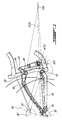
- a bicycle frame assembly according to a particular embodiment of the present invention is generally shown at 10, and comprises a rear suspension system linkage assembly 12 and a main frame 20.
- the main frame 20 is manufactured out of aluminum, steel, carbon-fiber, or any other adequate material.
- the main frame 20 comprises a seat tube 13, a down tube 15, a top tube 17, a head tube 19, and a bottom bracket 22.
- the bottom bracket 22 defines a crank axis 23 therethrough, about which the bicycle's pedal cranks rotate.
- the seat tube 13 rigidly connects the bottom bracket 22 and the top tube 17.
- the seat tube 13 is of "partial length", i.e. rigidly suspended only from one of the tubes such as the top tube 17, for example.
- the main frame 20 is a single large structure rather than the aforementioned assembly of distinct tubes, such as a monocoque-type frame section which can be made for example of carbon fiber or sheet metal.
- a springing and damping mechanism, or shock absorbing member, such as a shock absorber 24, is pivotally attached to the main frame 20, by a lower shock mounting bracket 21.
- the lower shock mounting bracket 21 is secured within the main frame 20 between the seat tube 13 and the down tube 15, such as by welding or brazing.
- the shock absorber 24 provides a compression resistance force against which the rear suspension system linkage assembly 12 operates.
- the shock absorber 24 can alternately be mounted with equal effect elsewhere within the main frame 20 by attaching it to one or more of the other tubes, or outside the main frame 20, such as between an upper link member and the seat tube, for example.
- the shock absorber 24 acts to counter any forces that may be applied to the rear suspension linkage assembly 12 by the rear wheel so as to tend to maintain the relative positions of the main frame 20 and the rear suspension linkage assembly 12 constant. Doing so thereby also tends to attempt to keep the rear wheel in substantially continuous contact with the ground thereby affording the rider greater control of the vehicle than would occur if the rear wheel is permitted to leave contact with the ground for significant periods of time. Having the rear wheel out of ground contact results in a significant decrease in the rider's ability to exert control over the vehicle. By doing so, the shock absorber 24 absorbs much of the energy which enters the vehicle through the rear wheel rather than having that energy transferred through the main frame 20 to the rider. As a result the rider experiences a more comfortable ride and is able to maintain better control over the vehicle. This is of particular significance when the vehicle is operated over highly uneven terrain such as takes place in the operation of mountain bicycles.
- the linkage assembly 12 includes a pair of upper link members 26, a pair of lower link members 28, and a pair of rear stay members 30.
- the rear wheel of the bicycle is mounted between the pair of rear stay members 30 at dropouts 35 provided at the lower ends thereof.
- the rear wheel's axle, and, therefore, the rear wheel's central axis 36 is mounted within the dropouts 35.
- the rear ends of the lower link members 28 are pivotally connected to the rear stay members 30 at a rear pivot point 34, and the front ends of the lower link members 28 are pivotally connected to the seat tube 13 of the main frame 20 at a front pivot point 32.
- the front pivot point 32 is located proximate the crank axis 23, and the rear pivot point 34 is located proximate the rear wheel's axis.
- the lower link members 28 are located such that their primary axis (i.e. the axis extending through the pivots 32, 34) is above the rear wheel axis 36 (i.e. the transverse axis extending through the axle of the rear wheel) throughout the travel of the rear wheel.
- the lower link members 28 are also located such that the portion of their primary axis defined between the pivots 32, 34 remains below the Average Chain Torque Line (ACTL) of the suspension system throughout the travel of the rear wheel.
- the average chain torque line represents the average of the various chain torque lines for possible gear selections at each given position throughout the wheel travel (i.e. compression level of the suspension system).
- the chain torque line is defined as a line extending along the tension side of the chain positioned on the chain rings (sprockets) of the bicycle.
- the chain torque line is substantially tangent to the front and rear chain rings of the bicycle, and represents the line of action of torque transmission between the front pedal crank and the rear sprocket driving the rear wheel.
- the low position of the lower link members 28 and of the front pivot point 32 in particular advantageously reduces the load applied to the upper portion of the seat tube 13 and as such increases the overall stiffness and strength of the linkage assembly 12.
- the rear ends of the upper link members 26 are pivotally connected to the top of the rear stay members 30 at a rear pivot point 38.
- the upper link members 26 are further pivotally connected, at an intermediate pivot point 40 which is located intermediate of their ends, to the seat tube 13 of the main frame 20.
- the intermediate pivot point 40 is substantially higher on the main frame 20 than is the front pivot point 32 of the lower link members 28.
- the front ends of the upper link members 26 are pivotally connected to the top of the shock absorber 24 at a shock pivot point 42.
- two link members 26 and two rear stay members 30 are provided, one of each type of member being located on a respective side of the vehicle's rear wheel and being symmetrical with the other.
- Two lower link members 28 are also provided, one on each side of the vehicle's rear wheel.
- the lower link members 28 are not symmetrical but are connected by the same pivots, so that their effective lengths are symmetrical. Alternately, all members can be symmetrical or asymmetrical, or only a single set of members can be used, i.e. located on a single side of the rear wheel.
- each of the members which comprises the rear suspension linkage assembly 12 is preferably formed so as to be joined by a yoke to its counterpart member. As such, any potential that might otherwise occur for the counterpart members to twist vis-à-vis each other is thereby reduced significantly.
- means can be provided for permitting the rider to be able to adjust the rear suspension system in order to adapt the system to variations in the terrain over which the vehicle is being operated, i.e. to restrict the length of the rear wheel travel for smooth terrain riding and allow for a maximum rear wheel travel for rougher terrain riding, with optionally one or more intermediate positions in between.
- Such means can include having a variable position for the pivot point 42, such as by providing the pivot point 42 in the form of a bolt or removable locking or quick release pin received in one of several holes, a crank controlling a rack and pinion arrangement, a spring biased detent pin and track, by incorporating complimentary locking surfaces on the bolt and upper link members combined with a continuous slot whereby the tightening of the bolt causes the surfaces to bind against each other, etc.
- the instantaneous center of rotation (ICR) of the linkage assembly 12 is generally determined by the intersection of a first axis extending through the pivots 38, 40 of the upper link member 26 and of a second axis extending through the pivots 32, 34 of the lower link member 28.
- 34' and 38' are used to schematically indicate the position of the pivots 34 and 38 in the compressed position of the suspension system, while plain lines illustrate the various elements in the fully extended position, that is, the position where the suspension system is located when no loads are being applied to the system.
- the pedaling efficiency (E ped ) is, in at least one embodiment, directly proportional to the chain force (F) and inversely proportional to the distance (L) from the average chain torque line to the instantaneous center of rotation. This distance (L) from the average chain torque line to the instantaneous center of rotation is negative when the ICR is below the ACTL, thus causing the pedaling efficiency (E ped ) to be negative as well.
- the travel path of the rear wheel axis 36 does not follow a semi-circular shape 54, as would be the case with a rear wheel's axis pivoting about a fixed pivot point.
- the travel path is in fact between a semi-circular shape and a vertical line, which in combination with a limited but sufficient amount of chain stay length growth (as will be detailed further below) provides an "energy transfer effect" increasing pedaling efficiency, especially when going uphill, as the suspension produces a force quickly returning the rear wheel to the pedaling position when driving over an obstacle, while limiting the amount of pedaling energy wasted by the suspension system. Therefore, the pedaling efficiency is not sacrificed for rear wheel travel, such that the suspension reacts largely to ground forces only and suspension activation is minimized even while the rider is pedaling hard.
- a rear wheel trajectory 100 for an example of a suspension system such as previously described and shown in Figs. 1-2 (hereinafter "the exemplary suspension system") is graphically shown.
- the rear wheel axis 36 in the fully compressed position is located approximately between 7% and 14% of the vertical travel in front of its location in the fully extended position, for example 16mm in front of its location in the fully extended position for a vertical travel of 140mm.
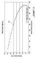
- an instantaneous suspension rate 102 as a function of shock stroke for the exemplary suspension system is graphically shown, in comparison with an instantaneous suspension rate 104 of a suspension system of a prior design (hereinafter "the prior suspension system"), which is exemplified in U.S. patent No. 6,843,494, issued Jan. 18, 2005 to Lam , the entire contents of which is incorporated herein by reference.
- the suspension rate 102 of the exemplary suspension system remains slightly more level than that of the prior suspension system, starting at a higher initial rate and finishing at a lower bottom-out rate.
- This more leveled curve in combination with the use of a longer stroke shock (for example 0.25 inches longer) advantageously allows for a more unrestrictive movement through the suspension travel, and the higher initial rate allows for a lower air pressure required in the shock absorber.
- the rising rate of the exemplary suspension system can advantageously be higher than that of the prior suspension system, and in a particular embodiment, is approximately 2 times higher.
- the difference in variation of the instantaneous suspension rate is caused by the length difference between the lower link member 28 and the upper link member 26 being greater for the exemplary suspension system than for the prior suspension system (in a particular embodiment, approximately 3 times greater), thus increasing the counterclockwise rotation of the rear stay member 30 as viewed from the drive side of the bicycle.
- the variation between the initial and bottom-out instantaneous suspension rate is between about 0.34 to about 0.45. The reduced variation in the instantaneous suspension rate facilitates the use of the entire travel of the suspension without sitting too far into the travel initially.
- the first derivative 106 of the instantaneous suspension rate 102 of the exemplary suspension system is graphically shown, in comparison with the first derivative 108 of the instantaneous suspension rate 104 of the prior suspension system.
- a corresponding linear approximation 110 is also shown for the first derivative 108 of the prior suspension system.
- the first derivative 106 of the exemplary suspension system is a third order polynomial curve, and therefore has a continuously changing curvature.
- the rate of change 106 of the instantaneous suspension rate for the exemplary suspension system is increasing for approximately the first 50% of suspension travel, and decreasing for the remaining suspension travel.
- the first portion of travel where the instantaneous suspension rate is continuously increasing causes the wheel to gradually ramp up to the point of inflexion following an exponential tendency
- the second portion of travel where the instantaneous suspension rate is continuously decreasing causes the wheel to gradually decrease to the bottom-out rate following a logarithmic tendency.
- This type of variation of the instantaneous suspension rate provides the rider with a more comfortable ride since the suspension does not feel as harsh as a suspension having a continuously decreasing rate of change for the instantaneous suspension rate, as shown at 108, 110 for the prior suspension system.
- a chain stay length 112 as a function of shock stroke of the exemplary suspension system is graphically shown, in comparison with the chain stay length 114 of the prior suspension system. It can be seen that the chain stay length growth throughout travel for the exemplary suspension system is approximately 9.5mm, while in the prior suspension system it is approximately 17mm.
- the reduced chain stay length growth of the exemplary suspension system advantageously allows for a reduction of pedal feedback, which is the force felt when the rear wheel hits a bump and chain stay lengthening causes the chain to apply a rearward torque at the bottom bracket spindle.
- the chain stay lengthening is reduced in the exemplary suspension system, some chain stay lengthening is still maintained, which as mentioned above produces the desired "energy transfer effect" quickly returning the rear wheel to the pedaling position when driving over an obstacle and limiting the suspension travel when pedaling uphill.
- a chain stay length growth which is too high would result in excessive pedal feedback and as such would feel uncomfortable to the rider, while a chain stay length growth which is too low would not produce the desired result.
- the chain stay length growth is between about 8 to 17mm for a vertical travel of about 140mm, or between about 5% and 12% of the vertical wheel travel, to produce the above-mentioned "energy transfer effect".
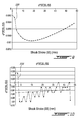
- the first derivative 116 of the curve of chain stay length 112 of the exemplary suspension system is graphically shown in Fig. 7
- the first derivative 118 of the curve of chain stay length 114 of the prior suspension system is graphically shown in Fig. 8
- the second derivative 120 of the curve of chain stay length 112 of the exemplary suspension system is graphically shown in Fig. 9
- the second derivative 122 of the prior suspension system is graphically shown in Fig. 10 .
- the prior suspension system exhibits a continuously decreasing rate of variation of the chain stay length rate of change as the suspension compresses
- the exemplary suspension system exhibits an increasing rate of variation of the chain stay length rate of change for a first portion of the travel and a decreasing rate of variation of the chain stay length rate of change for the remainder of the travel.
- the increasing then decreasing rate of variation of the chain stay length rate of change provides the rider with a more comfortable ride since the suspension does not feel as harsh as a suspension having a continuously decreasing rate of variation of the chain stay length rate of change such as the prior suspension system.
Landscapes
- Engineering & Computer Science (AREA)
- Mechanical Engineering (AREA)
- Axle Suspensions And Sidecars For Cycles (AREA)
Abstract
Description
- The present invention relates generally to two-wheeled vehicles, particularly bicycles, and more specifically to a rear wheel suspension for such bicycles.
- Rear wheel suspension systems have been used on a variety of two-wheeled vehicles, including motorcycles, scooters and bicycles, for providing improved rider comfort and increased performance.
- Rear wheel suspensions on pedal powered bicycles have become increasingly popular, and generally provide a rider with the benefits of a more comfortable ride and better control over the bicycle. Such bicycle suspension systems improve ride quality by absorbing the energy incurred from encountering ground obstacles, rather than transmitting them through the frame to the rider. By maintaining greater contact between the tire and the ground, the suspension also provides the rider with better control for accelerating, braking, and cornering.
- For a suspension to be suitable for use on a bicycle, it must be efficient. Ideally, a perfect rear wheel suspension would compress only in reaction to ground forces but not to drive-train or braking forces. Unwanted suspension movement resulting from drive train forces wastes rider energy.
- Accordingly, there exists a need for an improved bicycle rear wheel suspension which reacts principally to ground forces and limits the action of drive-train and braking forces thereon.
- It is therefore an aim of the present invention to provide an improved rear wheel suspension system for a bicycle.
- Therefore, in accordance with the present invention, there is provided a bicycle frame set comprising: a main frame including at least a seat tube, a top tube, a head tube, a down tube, and a bottom bracket fixed to at least one of the seat tube and the down tube; and a rear wheel suspension system pivotally attached to the main frame, the rear wheel suspension system comprising: an upper link pivotally attached to the main frame at a first pivot point; a rear stay member having an upper end pivotally attached to the upper link at a second pivot point and a lower end having a dropout receiving a rear wheel axle of the bicycle, the rear wheel axle defining an axle axis about which the rear wheel rotates when mounted to the dropout; a lower link pivotally attached to the main frame at a third pivot point located on said main frame at a lower vertical elevation than the first pivot point, and the lower link being pivotally attached to the rear stay member at a fourth pivot point located on said rear stay member below said upper end thereof; and a shock absorber having a first end pivotally connected to the upper link and a second end pivotally connected to the main frame; wherein an instantaneous center of rotation is defined at an intersection between an upper axis extending through the first and second pivots and a lower axis extending through the third and fourth pivots, and an average chain torque line of the bicycle frame set is defined as an average of a number of possible chain torque lines extending along a tension side of a chain when the chain is positioned on chain sprockets of the bicycle frame set; and wherein, throughout a travel distance of the shock absorber, the instantaneous center of rotation remains below the average chain torque line, the lower axis remains above the axle axis, and a portion of the lower axis defined between the third and fourth pivots extends below the average chain torque line.
- Also in accordance with the present invention, there is provided a bicycle comprising: a frame including a bottom bracket, a seat tube, a top tube, a head tube, and a down tube; and a rear wheel suspension system including: an upper link pivotally attached to the frame at a first pivot point; a rear stay member having an upper end pivotally attached to the upper link at a second pivot point and a lower end having a dropout within which an axle of a rear wheel of the bicycle is engaged, the rear wheel axle defining an axle axis about which the rear wheel rotates; a lower link pivotally attached to the main frame at a third pivot point located on said main frame at a lower vertical elevation than the first pivot point, and the lower link being pivotally attached to the rear stay member at a fourth pivot point located on said rear stay member below said upper end thereof; and a shock absorber having a first end pivotally connected to the upper link and a second end pivotally connected to the main frame; wherein an instantaneous center of rotation is defined at an intersection between an upper axis extending through the first and second pivots and a lower axis extending through the third and fourth pivots, and an average chain torque line of the bicycle frame set is defined as an average of a number of possible chain torque lines extending along a tension side of a chain when the chain is positioned on chain sprockets of the bicycle frame set; and wherein, throughout a travel distance of the shock absorber, the instantaneous center of rotation remains below the average chain torque line, the lower axis remains above the axle axis, and a portion of the lower axis defined between the third and fourth pivots extends below the average chain torque line.
- There is also provided, in accordance with another aspect of the present invention, a method of making a bicycle having a main frame and a rear wheel suspension system including a rear stay member pivotally attached to the main frame by upper and lower link members and a shock absorber mounted between the main frame and the upper link member, the upper and lower link members each having a forward and a rearward pivot thereon and respectively defining an upper and lower link axis extending between each of the forward and rearward pivots, a rear wheel of the bicycle having an axle mounted to the rear stay member, the axle defining an axle axis extending therethrough, the method comprising the step of: designing the rear wheel suspension system to have characteristics which remain throughout a travel distance of the shock absorber, said characteristics including an instantaneous center of rotation which remains below an average chain torque line, while the lower link axis remains above the axle axis and at least a portion of the lower link axis extends below the average chain torque line; and assembling the rear wheel suspension system by pivotally mounting the upper and lower link members to the main frame and the rear stay member in a relative geometric relationship which provides the designed characteristics of the rear wheel suspension system; wherein the instantaneous center of rotation is defined as a point at an intersection of the upper and lower link axis, and the average chain torque line is defined as an average of chain torque lines extending along a tension side of a chain of the bicycle when the chain is positioned on chain sprockets of the bicycle.
- There is further provided, in accordance with another aspect of the present invention, a method of improving riding performance of a bicycle having a main frame and a rear wheel suspension system including a rear stay member pivotally attached to the main frame by upper and lower link members and a shock absorber mounted between the main frame and the upper link member, a rear wheel of the bicycle rotating about a rear wheel axle mounted to the rear stay member, the method comprising the steps of: defining an average chain torque line of the rear wheel suspension system by determining an average of a number of possible chain torque lines extending along a tension side of a chain when the chain of the bicycle when positioned on chain sprockets of the bicycle; defining an upper axis extending through first and second pivots of the upper link member and defining a lower axis extending through third and fourth pivots of the lower link member; defining an instantaneous center of rotation at an intersection between the upper axis and the lower axis; ensuring that the instantaneous center of rotation remains below the average chain torque line throughout a travel distance of the rear wheel suspension; ensuring that the lower axis remains above a transverse axle axis, extending through the rear wheel axle, throughout the travel distance of the rear wheel suspension; and ensuring that at least a portion of the lower axis defined between the third and fourth pivots of the lower link member extends below the average chain torque line throughout the travel distance of the rear wheel suspension.
- Reference will now be made to the accompanying drawings, showing by way of illustration a particular embodiment of the present invention and in which:
-
Fig. 1 is a schematic side view of a bicycle frame including a rear suspension system according to a particular embodiment of the present invention; -
Fig. 2 is a schematic side view of part of the frame and suspension system ofFig. 1 , showing the suspension system in fully compressed and fully extended positions; -
Fig. 3 is a graphical representation of a rear wheel trajectory of an example of a suspension system such as shown inFig. 1 ; -
Fig. 4 is a graphical representation of an instantaneous suspension rate of an example of a suspension system such as shown inFig. 1 and of an example of a suspension system in accordance with a prior design; -
Fig. 5 is a graphical representation of the first derivative of the curves ofFig. 4 ; -
Fig. 6 is a graphical representation of a chain stay length of an example of a suspension system such as shown inFig. 1 and of an example of a suspension system in accordance with a prior design; -
Figs. 7 and 8 are graphical representations of the first derivative of the curves ofFig. 6 ; and -
Figs. 9 and 10 are graphical representations of the second derivative of the curves ofFig. 6 . - Referring to
Fig. 1 , a bicycle frame assembly according to a particular embodiment of the present invention is generally shown at 10, and comprises a rear suspensionsystem linkage assembly 12 and amain frame 20. In a particular embodiment, themain frame 20 is manufactured out of aluminum, steel, carbon-fiber, or any other adequate material. - The
main frame 20 comprises aseat tube 13, adown tube 15, atop tube 17, ahead tube 19, and abottom bracket 22. Thebottom bracket 22 defines acrank axis 23 therethrough, about which the bicycle's pedal cranks rotate. In the embodiment shown, theseat tube 13 rigidly connects thebottom bracket 22 and thetop tube 17. In an alternate embodiment, theseat tube 13 is of "partial length", i.e. rigidly suspended only from one of the tubes such as thetop tube 17, for example. - In an alternate embodiment, the
main frame 20 is a single large structure rather than the aforementioned assembly of distinct tubes, such as a monocoque-type frame section which can be made for example of carbon fiber or sheet metal. - A springing and damping mechanism, or shock absorbing member, such as a shock absorber 24, is pivotally attached to the
main frame 20, by a lowershock mounting bracket 21. In the embodiment shown, the lowershock mounting bracket 21 is secured within themain frame 20 between theseat tube 13 and thedown tube 15, such as by welding or brazing. Theshock absorber 24 provides a compression resistance force against which the rear suspensionsystem linkage assembly 12 operates. In an alternate embodiment, theshock absorber 24 can alternately be mounted with equal effect elsewhere within themain frame 20 by attaching it to one or more of the other tubes, or outside themain frame 20, such as between an upper link member and the seat tube, for example. - The shock absorber 24 acts to counter any forces that may be applied to the rear
suspension linkage assembly 12 by the rear wheel so as to tend to maintain the relative positions of themain frame 20 and the rearsuspension linkage assembly 12 constant. Doing so thereby also tends to attempt to keep the rear wheel in substantially continuous contact with the ground thereby affording the rider greater control of the vehicle than would occur if the rear wheel is permitted to leave contact with the ground for significant periods of time. Having the rear wheel out of ground contact results in a significant decrease in the rider's ability to exert control over the vehicle. By doing so, the shock absorber 24 absorbs much of the energy which enters the vehicle through the rear wheel rather than having that energy transferred through themain frame 20 to the rider. As a result the rider experiences a more comfortable ride and is able to maintain better control over the vehicle. This is of particular significance when the vehicle is operated over highly uneven terrain such as takes place in the operation of mountain bicycles. - The
linkage assembly 12 includes a pair ofupper link members 26, a pair oflower link members 28, and a pair ofrear stay members 30. The rear wheel of the bicycle is mounted between the pair ofrear stay members 30 atdropouts 35 provided at the lower ends thereof. Hence, the rear wheel's axle, and, therefore, the rear wheel'scentral axis 36, is mounted within thedropouts 35. - The rear ends of the
lower link members 28 are pivotally connected to therear stay members 30 at arear pivot point 34, and the front ends of thelower link members 28 are pivotally connected to theseat tube 13 of themain frame 20 at afront pivot point 32. Thefront pivot point 32 is located proximate thecrank axis 23, and therear pivot point 34 is located proximate the rear wheel's axis. Thelower link members 28 are located such that their primary axis (i.e. the axis extending through thepivots 32, 34) is above the rear wheel axis 36 (i.e. the transverse axis extending through the axle of the rear wheel) throughout the travel of the rear wheel. Thelower link members 28 are also located such that the portion of their primary axis defined between thepivots lower link members 28 and of thefront pivot point 32 in particular advantageously reduces the load applied to the upper portion of theseat tube 13 and as such increases the overall stiffness and strength of thelinkage assembly 12. - The rear ends of the
upper link members 26 are pivotally connected to the top of therear stay members 30 at arear pivot point 38. Theupper link members 26 are further pivotally connected, at anintermediate pivot point 40 which is located intermediate of their ends, to theseat tube 13 of themain frame 20. Theintermediate pivot point 40 is substantially higher on themain frame 20 than is thefront pivot point 32 of thelower link members 28. Additionally, the front ends of theupper link members 26 are pivotally connected to the top of the shock absorber 24 at ashock pivot point 42. - The effective length of the
lower link member 28, i.e. the distance between thepivot points upper link member 26, i.e. the distance between thepivot points lower link member 28 is approximately 3.7 times greater than the effective length of theupper link member 26. - In the embodiment shown, two
link members 26 and tworear stay members 30 are provided, one of each type of member being located on a respective side of the vehicle's rear wheel and being symmetrical with the other. Twolower link members 28 are also provided, one on each side of the vehicle's rear wheel. Thelower link members 28 are not symmetrical but are connected by the same pivots, so that their effective lengths are symmetrical. Alternately, all members can be symmetrical or asymmetrical, or only a single set of members can be used, i.e. located on a single side of the rear wheel. - Although not shown, each of the members (
rear stay members 30,upper link members 26, and lower link members 28) which comprises the rearsuspension linkage assembly 12 is preferably formed so as to be joined by a yoke to its counterpart member. As such, any potential that might otherwise occur for the counterpart members to twist vis-à-vis each other is thereby reduced significantly. - Although not shown, means can be provided for permitting the rider to be able to adjust the rear suspension system in order to adapt the system to variations in the terrain over which the vehicle is being operated, i.e. to restrict the length of the rear wheel travel for smooth terrain riding and allow for a maximum rear wheel travel for rougher terrain riding, with optionally one or more intermediate positions in between. Such means can include having a variable position for the
pivot point 42, such as by providing thepivot point 42 in the form of a bolt or removable locking or quick release pin received in one of several holes, a crank controlling a rack and pinion arrangement, a spring biased detent pin and track, by incorporating complimentary locking surfaces on the bolt and upper link members combined with a continuous slot whereby the tightening of the bolt causes the surfaces to bind against each other, etc. - Referring to
Fig. 2 , the instantaneous center of rotation (ICR) of thelinkage assembly 12 is generally determined by the intersection of a first axis extending through thepivots upper link member 26 and of a second axis extending through thepivots lower link member 28. In the Figure, 34' and 38' are used to schematically indicate the position of thepivots assembly 12 throughout the entire wheel travel remains forward of thecrank axis 23, remains below and close to the corresponding Average Chain torque Line (ACTL, ACTL'), and gets progressively lower as the suspension compresses. - Maintaining the instantaneous center of rotation close to the average chain torque line advantageously allows for the minimization of the squat effect produced by having the instantaneous center of rotation below the average chain torque line, thus allowing the suspension to work independently from pedaling forces and as such improve pedaling efficiency. In a particular embodiment, at 20% sag where the suspension is at the average pedaling position, the instantaneous center of rotation is in close proximity to the average chain torque line. The pedaling efficiency (Eped) is, in at least one embodiment, directly proportional to the chain force (F) and inversely proportional to the distance (L) from the average chain torque line to the instantaneous center of rotation. This distance (L) from the average chain torque line to the instantaneous center of rotation is negative when the ICR is below the ACTL, thus causing the pedaling efficiency (Eped) to be negative as well.
- It can also be seen that the travel path of the
rear wheel axis 36 does not follow asemi-circular shape 54, as would be the case with a rear wheel's axis pivoting about a fixed pivot point. The travel path is in fact between a semi-circular shape and a vertical line, which in combination with a limited but sufficient amount of chain stay length growth (as will be detailed further below) provides an "energy transfer effect" increasing pedaling efficiency, especially when going uphill, as the suspension produces a force quickly returning the rear wheel to the pedaling position when driving over an obstacle, while limiting the amount of pedaling energy wasted by the suspension system. Therefore, the pedaling efficiency is not sacrificed for rear wheel travel, such that the suspension reacts largely to ground forces only and suspension activation is minimized even while the rider is pedaling hard. - Referring to
Fig. 3 , arear wheel trajectory 100 for an example of a suspension system such as previously described and shown inFigs. 1-2 (hereinafter "the exemplary suspension system") is graphically shown. In a particular embodiment, therear wheel axis 36 in the fully compressed position is located approximately between 7% and 14% of the vertical travel in front of its location in the fully extended position, for example 16mm in front of its location in the fully extended position for a vertical travel of 140mm. - Referring to
Fig. 4 , aninstantaneous suspension rate 102 as a function of shock stroke for the exemplary suspension system is graphically shown, in comparison with aninstantaneous suspension rate 104 of a suspension system of a prior design (hereinafter "the prior suspension system"), which is exemplified inU.S. patent No. 6,843,494, issued Jan. 18, 2005 to Lam , the entire contents of which is incorporated herein by reference. The instantaneous suspension rate is computed as:
- It can be seen that the
suspension rate 102 of the exemplary suspension system remains slightly more level than that of the prior suspension system, starting at a higher initial rate and finishing at a lower bottom-out rate. This more leveled curve, in combination with the use of a longer stroke shock (for example 0.25 inches longer) advantageously allows for a more unrestrictive movement through the suspension travel, and the higher initial rate allows for a lower air pressure required in the shock absorber. As such, the rising rate of the exemplary suspension system can advantageously be higher than that of the prior suspension system, and in a particular embodiment, is approximately 2 times higher. The difference in variation of the instantaneous suspension rate is caused by the length difference between thelower link member 28 and theupper link member 26 being greater for the exemplary suspension system than for the prior suspension system (in a particular embodiment, approximately 3 times greater), thus increasing the counterclockwise rotation of therear stay member 30 as viewed from the drive side of the bicycle. In a particular embodiment adapted for long distance cross-country marathon cycling, e.g. when the rider is not expected to drop the bicycle more than 4 feet as opposed to a freeride or downhill rider, the variation between the initial and bottom-out instantaneous suspension rate is between about 0.34 to about 0.45. The reduced variation in the instantaneous suspension rate facilitates the use of the entire travel of the suspension without sitting too far into the travel initially. - Referring to
Fig. 5 , thefirst derivative 106 of theinstantaneous suspension rate 102 of the exemplary suspension system is graphically shown, in comparison with thefirst derivative 108 of theinstantaneous suspension rate 104 of the prior suspension system. A correspondinglinear approximation 110 is also shown for thefirst derivative 108 of the prior suspension system. It can be seen that thefirst derivative 106 of the exemplary suspension system is a third order polynomial curve, and therefore has a continuously changing curvature. Generally speaking, in the example shown, the rate ofchange 106 of the instantaneous suspension rate for the exemplary suspension system is increasing for approximately the first 50% of suspension travel, and decreasing for the remaining suspension travel. The first portion of travel where the instantaneous suspension rate is continuously increasing causes the wheel to gradually ramp up to the point of inflexion following an exponential tendency, while the second portion of travel where the instantaneous suspension rate is continuously decreasing causes the wheel to gradually decrease to the bottom-out rate following a logarithmic tendency. This type of variation of the instantaneous suspension rate provides the rider with a more comfortable ride since the suspension does not feel as harsh as a suspension having a continuously decreasing rate of change for the instantaneous suspension rate, as shown at 108, 110 for the prior suspension system. - Referring to
Fig. 6 , an example of achain stay length 112 as a function of shock stroke of the exemplary suspension system is graphically shown, in comparison with thechain stay length 114 of the prior suspension system. It can be seen that the chain stay length growth throughout travel for the exemplary suspension system is approximately 9.5mm, while in the prior suspension system it is approximately 17mm. The reduced chain stay length growth of the exemplary suspension system advantageously allows for a reduction of pedal feedback, which is the force felt when the rear wheel hits a bump and chain stay lengthening causes the chain to apply a rearward torque at the bottom bracket spindle. While the chain stay lengthening is reduced in the exemplary suspension system, some chain stay lengthening is still maintained, which as mentioned above produces the desired "energy transfer effect" quickly returning the rear wheel to the pedaling position when driving over an obstacle and limiting the suspension travel when pedaling uphill. A chain stay length growth which is too high would result in excessive pedal feedback and as such would feel uncomfortable to the rider, while a chain stay length growth which is too low would not produce the desired result. As such, in a particular embodiment, the chain stay length growth is between about 8 to 17mm for a vertical travel of about 140mm, or between about 5% and 12% of the vertical wheel travel, to produce the above-mentioned "energy transfer effect". - The
first derivative 116 of the curve ofchain stay length 112 of the exemplary suspension system is graphically shown inFig. 7 , thefirst derivative 118 of the curve ofchain stay length 114 of the prior suspension system is graphically shown inFig. 8 , thesecond derivative 120 of the curve ofchain stay length 112 of the exemplary suspension system is graphically shown inFig. 9 , and thesecond derivative 122 of the prior suspension system is graphically shown inFig. 10 . It can be seen that the prior suspension system exhibits a continuously decreasing rate of variation of the chain stay length rate of change as the suspension compresses, while the exemplary suspension system exhibits an increasing rate of variation of the chain stay length rate of change for a first portion of the travel and a decreasing rate of variation of the chain stay length rate of change for the remainder of the travel. The increasing then decreasing rate of variation of the chain stay length rate of change provides the rider with a more comfortable ride since the suspension does not feel as harsh as a suspension having a continuously decreasing rate of variation of the chain stay length rate of change such as the prior suspension system. - The embodiments of the invention described above are intended to be exemplary. Those skilled in the art will therefore appreciate that the foregoing description is illustrative only, and that various alternate configurations and modifications can be devised without departing from the spirit of the present invention. Accordingly, the present invention is intended to embrace all such alternate configurations, modifications and variances which fall within the scope of the appended claims.
Claims (21)
- A bicycle frame set comprising:a main frame including at least a seat tube, a top tube, a head tube, a down tube, and a bottom bracket fixed to at least one of the seat tube and the down tube; anda rear wheel suspension system pivotally attached to the main frame, the rear wheel suspension system comprising:an upper link pivotally attached to the main frame at a first pivot point;a rear stay member having an upper end pivotally attached to the upper link at a second pivot point and a lower end having a dropout receiving a rear wheel axle of the bicycle, the rear wheel axle defining an axle axis about which the rear wheel rotates when mounted to the dropout;a lower link pivotally attached to the main frame at a third pivot point located on said main frame at a lower vertical elevation than the first pivot point, and the lower link being pivotally attached to the rear stay member at a fourth pivot point located on said rear stay member below said upper end thereof; anda shock absorber having a first end pivotally connected to the upper link and a second end pivotally connected to the main frame;wherein an instantaneous center of rotation is defined at an intersection between an upper axis extending through the first and second pivots and a lower axis extending through the third and fourth pivots, and an average chain torque line of the bicycle frame set is defined as an average of a number of possible chain torque lines extending along a tension side of a chain when the chain is positioned on chain sprockets of the bicycle frame set; andwherein, throughout a travel distance of the shock absorber, the instantaneous center of rotation remains below the average chain torque line, the lower axis remains above the axle axis, and a portion of the lower axis defined between the third and fourth pivots extends below the average chain torque line.
- The bicycle frame set according to claim 1, wherein the instantaneous center of rotation at the intersection between the upper axis and the lower axis moves away from the average chain torque line as the shock absorber compresses.
- The bicycle frame set according to claim 1 or 2, wherein the instantaneous center of rotation at the intersection between the upper axis and the lower axis moves toward the bottom bracket as the shock absorber compresses.
- The bicycle frame set according to any one of claims 1 to 3, wherein a distance between the rear wheel axle and the bottom bracket increases continuously as the shock absorber compresses, the increase in distance between the bottom bracket and the rear wheel axle being between 5% and 12% of a vertical travel distance of the rear wheel axle throughout the travel distance of the shock absorber.
- The bicycle frame set according to claim 4, wherein a rate of change of the distance between the rear wheel axle and the bottom bracket has a rate of change which increases for a first portion of the travel of the rear wheel axle and decreases for a remaining portion of the travel of the rear wheel axle.
- The bicycle frame set according to any one of claims 1 to 5, wherein an instantaneous suspension rate of the rear wheel suspension system varies within a range of 0.34 to 0.45 throughout the travel distance of the shock absorber.
- The bicycle frame set according to claim 6, wherein the instantaneous suspension rate has a rate of change which increases for a first portion of the travel distance and decreases for a remaining portion of the travel distance.
- The bicycle frame set according to claim 7, wherein the first portion is approximately 50% of the travel distance.
- The bicycle frame set according to any one of claims 1 to 8, wherein the fourth pivot point is located on the rear stay member between the upper and lower ends thereof.
- The bicycle frame set according to claim 9, wherein the fourth pivot point is located proximate the lower end of the rear stay member at a point thereon disposed above the axle axis and below the average chain torque line.
- A bicycle comprising a bicycle frame set according to any one of claims 1 to 10.
- A method of making a bicycle having a main frame and a rear wheel suspension system including a rear stay member pivotally attached to the main frame by upper and lower link members and a shock absorber mounted between the main frame and the upper link member, the upper and lower link members each having a forward and a rearward pivot thereon and respectively defining an upper and lower link axis extending between each of the forward and rearward pivots, a rear wheel of the bicycle having an axle mounted to the rear stay member, the axle defining an axle axis extending therethrough, the method comprising the step of:designing the rear wheel suspension system to have characteristics which remain throughout a travel distance of the shock absorber, said characteristics including an instantaneous center of rotation which remains below an average chain torque line, while the lower link axis remains above the axle axis and at least a portion of the lower link axis extends below the average chain torque line; andassembling the rear wheel suspension system by pivotally mounting the upper and lower link members to the main frame and the rear stay member in a relative geometric relationship which provides the designed characteristics of the rear wheel suspension system;wherein the instantaneous center of rotation is defined as a point at an intersection of the upper and lower link axis, and the average chain torque line is defined as an average of chain torque lines extending along a tension side of a chain of the bicycle when the chain is positioned on chain sprockets of the bicycle.
- The method according to claim 12, wherein the step of designing further includes designing the instantaneous center of rotation to move away from the average chain torque line as the shock absorber compresses.
- The method according to claim 12 or 13, further comprising designing the instantaneous center of rotation to move toward a bottom bracket of the main frame as the shock absorber compresses.
- The method according to any one of claims 12 to 14, further comprising designing a distance between the rear wheel axle and a bottom bracket of the main frame to continuously increase as the shock absorber compresses, the increase in distance between the bottom bracket and the rear wheel axle being between 5% and 12% of a vertical travel distance of the rear wheel axle throughout the travel distance of the shock absorber.
- The method according to claim 15, further comprising designing a rate of change of the distance between the rear wheel axle and the bottom bracket to have a rate of change which increases for a first portion of the travel of the rear wheel axle and decreases for a remaining portion of the travel of the rear wheel axle.
- The method according to any one of claims 12 to 16, further comprising designing the rear wheel suspension system to have an instantaneous suspension rate which varies within a range of 0.34 to 0.45 throughout the travel distance of the shock absorber.
- The method according to claim 17, further comprising designing the instantaneous suspension rate to have a rate of change which increases for a first portion of the travel distance and decreases for a remaining portion of the travel distance.
- The method according to claim 18, further comprising defining the first portion to be approximately 50% of the travel distance of the shock absorber.
- The method according to any one of claims 12 to 19, wherein the step of assembling includes locating the rearward pivot of the lower link member on the rear stay member at a point thereon proximate a lower end of the rear stay member, said point on the rear stay member being disposed above the axle axis and below the average chain torque line.
- A method of making a bicycle having a main frame and a rear wheel suspension system including a rear stay member pivotally attached to the main frame by upper and lower link members and a shock absorber mounted between the main frame and the upper link member, the upper and lower link members each having a forward and a rearward pivot thereon and respectively defining an upper and lower link axis extending between each of the forward and rearward pivots, a rear wheel of the bicycle having an axle mounted to the rear stay member, the axle defining an axle axis extending therethrough,
wherein the rear wheel suspension system has characteristics which remain throughout a travel distance of the shock absorber, said characteristics including an instantaneous center of rotation which remains below an average chain torque line, while the lower link axis remains above the axle axis and at least a portion of the lower link axis extends below the average chain torque line;
the method comprising the step of:assembling the rear wheel suspension system by pivotally mounting the upper and lower link members to the main frame and the rear stay member in a relative geometric relationship which provides the characteristics of the rear wheel suspension system;wherein the instantaneous center of rotation is defined as a point at an intersection of the upper and lower link axis, and the average chain torque line is defined as an average of chain torque lines extending along a tension side of a chain of the bicycle when the chain is positioned on chain sprockets of the bicycle.
Applications Claiming Priority (1)
| Application Number | Priority Date | Filing Date | Title |
|---|---|---|---|
| US94253707P | 2007-06-07 | 2007-06-07 |
Publications (2)
| Publication Number | Publication Date |
|---|---|
| EP2000398A2 true EP2000398A2 (en) | 2008-12-10 |
| EP2000398A3 EP2000398A3 (en) | 2009-12-09 |
Family
ID=39415030
Family Applications (1)
| Application Number | Title | Priority Date | Filing Date |
|---|---|---|---|
| EP08103258A Ceased EP2000398A3 (en) | 2007-06-07 | 2008-03-31 | Bicycle rear suspension system |
Country Status (3)
| Country | Link |
|---|---|
| US (1) | US7635141B2 (en) |
| EP (1) | EP2000398A3 (en) |
| CA (1) | CA2621044C (en) |
Cited By (23)
| Publication number | Priority date | Publication date | Assignee | Title |
|---|---|---|---|---|
| EP2828144A4 (en) * | 2012-03-23 | 2015-12-23 | Sotto Group LLC | REAR SUSPENSION SYSTEM FOR BICYCLES |
| USD860061S1 (en) | 2018-02-08 | 2019-09-17 | Trvstper, Inc. | Cycle suspension assembly |
| USD861542S1 (en) | 2018-02-08 | 2019-10-01 | Trvstper, Inc. | Cycle suspension assembly |
| US10518836B2 (en) | 2017-07-27 | 2019-12-31 | Trvstper, Inc. | Suspension assembly for a cycle |
| US10518839B2 (en) | 2017-08-29 | 2019-12-31 | Trvstper, Inc. | Inline shock absorber with coil spring for a cycle wheel suspension assembly |
| US10526039B2 (en) | 2017-07-27 | 2020-01-07 | Trvstper, Inc. | Suspension assembly for a cycle |
| US10526040B2 (en) | 2017-08-28 | 2020-01-07 | Trvstper, Inc. | Inline shock absorber with gas spring for a cycle wheel suspension assembly |
| US10549812B2 (en) | 2017-08-28 | 2020-02-04 | Trvstper, Inc. | Inline shock absorber with gas spring for a cycle wheel suspension assembly |
| US10549813B2 (en) | 2017-08-29 | 2020-02-04 | Trvstper, Inc. | Inline shock absorber with coil spring for a cycle wheel suspension assembly |
| US10549815B2 (en) | 2017-07-27 | 2020-02-04 | Trvstper, Inc. | Suspension assembly for a bicycle |
| EP3494036A4 (en) * | 2016-08-04 | 2020-04-08 | Level One Engineering LLC | BICYCLE REAR SUSPENSION SYSTEM |
| FR3087185A1 (en) * | 2018-10-10 | 2020-04-17 | Vaxe | REAR WHEEL SUSPENSION BIKE FRAME |
| US10689061B2 (en) | 2017-07-27 | 2020-06-23 | Trvstper, Inc. | Suspension assembly for a cycle |
| US11084552B2 (en) | 2018-09-25 | 2021-08-10 | Specialized Bicycle Components, Inc. | Simplified gas spring setup for a trailing link cycle wheel suspension |
| US11208172B2 (en) | 2018-10-05 | 2021-12-28 | Specialized Bicycle Components, Inc. | Suspension pivot assemblies having a retention feature |
| US11230346B2 (en) | 2018-09-25 | 2022-01-25 | Specialized Bicycle Components Inc. | Cycle wheel suspension assembly having gas pistons with unequal gas piston areas |
| US11230347B2 (en) | 2018-09-25 | 2022-01-25 | Specialized Bicycle Components, Inc. | Cycle wheel suspension assembly having gas pistons with unequal gas piston areas |
| US11230348B2 (en) | 2018-09-25 | 2022-01-25 | Specialized Bicycle Components, Inc. | Trailing link cycle wheel suspension assembly having gas pistons with unequal gas piston areas |
| US11273887B2 (en) | 2018-10-16 | 2022-03-15 | Specialized Bicycle Components, Inc. | Cycle suspension with travel indicator |
| US11345432B2 (en) | 2018-10-12 | 2022-05-31 | Specialized Bicycle Components, Inc. | Suspension assembly for a cycle having a fork arm with dual opposing tapers |
| US11524744B2 (en) | 2019-04-09 | 2022-12-13 | Specialized Bicycle Components, Inc. | Cycle suspension with rotation sensor |
| US11945539B2 (en) | 2018-09-07 | 2024-04-02 | Specialized Bicycle Components, Inc. | Dual sided suspension assembly for a cycle wheel |
| US12319381B2 (en) | 2018-09-25 | 2025-06-03 | Specialized Bicycle Components, Inc. | Trailing link cycle wheel suspension assembly having gas pistons with unequal gas piston areas |
Families Citing this family (34)
| Publication number | Priority date | Publication date | Assignee | Title |
|---|---|---|---|---|
| EP1799534B1 (en) | 2004-09-15 | 2014-08-27 | Yeti Cycling LLC | Rear suspension system for a bicycle |
| US20070194550A1 (en) * | 2006-02-22 | 2007-08-23 | Frank Wadelton | Vehicle Wheel Suspension System |
| US8382136B2 (en) * | 2008-04-17 | 2013-02-26 | Sotto Group LLC | Bicycle rear suspension system linkage |
| US20090261557A1 (en) * | 2008-04-17 | 2009-10-22 | Sotto Llc | Bicycle Rear Suspension System |
| US20100007113A1 (en) * | 2008-07-11 | 2010-01-14 | David Earle | Rear suspension system for bicycles |
| US20100156066A1 (en) * | 2008-12-15 | 2010-06-24 | O'connor D Arcy | Mountain bicycle having improved frame geometry |
| US7954837B2 (en) * | 2009-06-30 | 2011-06-07 | Specialized Bicycle Components, Inc. | Bicycle assembly with gusset |
| US8439383B2 (en) | 2009-06-30 | 2013-05-14 | Specialized Bicycle Components, Inc. | Bicycle shock with extension arms |
| US7938425B2 (en) * | 2009-06-30 | 2011-05-10 | Specialized Bicycle Components, Inc. | Bicycle assembly with rear shock |
| US8066297B2 (en) * | 2009-07-21 | 2011-11-29 | Sotto, Llc | Bicycle rear suspension linkage |
| US8342552B1 (en) * | 2010-03-04 | 2013-01-01 | Felton Zimmerman | Self adjusting bicycle |
| US8006993B1 (en) | 2010-05-14 | 2011-08-30 | Specialized Bicycle Components, Inc. | Bicycle frame |
| US9102378B2 (en) | 2010-08-20 | 2015-08-11 | Yeti Cycling, Llc | Link suspension system |
| US9821879B2 (en) | 2010-08-20 | 2017-11-21 | Yeti Cycling, Llc | Reciprocating rail movement suspension system |
| US9039026B2 (en) | 2011-03-14 | 2015-05-26 | Christopher Hudec | Bicycle suspension system |
| US9216791B2 (en) * | 2011-03-14 | 2015-12-22 | Christopher Hudec | Bicycle suspension system |
| DE202011104974U1 (en) * | 2011-08-30 | 2012-12-03 | Canyon Bicycles Gmbh | bicycle frame |
| US8684388B1 (en) | 2012-11-26 | 2014-04-01 | Specialized Bicycle Components, Inc. | Head tube weld joint |
| US10766563B2 (en) | 2013-01-16 | 2020-09-08 | Yeti Cyclying, Llc | Rail suspension with integral shock and dampening mechanism |
| KR102039343B1 (en) * | 2013-03-26 | 2019-11-01 | 삼성전자주식회사 | Method and apparatus for determining mcs level in wireless mobile communication system |
| US9056647B2 (en) * | 2013-08-22 | 2015-06-16 | Samuel Hu | One-piece connector for a shock-absorbing frame of a bicycle |
| US9156521B2 (en) | 2013-12-23 | 2015-10-13 | Wayne Lumpkin | Bicycle frame rear suspension with flexing frame segment |
| CA2855104A1 (en) * | 2014-06-11 | 2015-12-11 | Industries Rad Inc. | Mountain bicycle with rear suspension having neutral braking trajectory |
| US10377442B2 (en) * | 2016-11-28 | 2019-08-13 | Brent Neilson | Suspension for a bicycle |
| EP3595963A4 (en) | 2017-03-17 | 2021-03-10 | Yeti Cycling, LLC | VEHICLE SUSPENSION LINK |
| US20210371045A9 (en) | 2017-03-17 | 2021-12-02 | Yeti Cycling, Llc | Vehicle Suspension Linkage |
| WO2019010394A1 (en) | 2017-07-07 | 2019-01-10 | Yeti Cycling, Llc | Vehicle suspension linkage |
| TWI636911B (en) * | 2017-08-17 | 2018-10-01 | 巨大機械工業股份有限公司 | Frame for bicycle |
| USD880369S1 (en) | 2018-02-08 | 2020-04-07 | Trvstper, Inc. | Cycle suspension assembly |
| US10850798B2 (en) * | 2018-03-30 | 2020-12-01 | Specialized Bicycle Components, Inc. | Bicycle rear suspension |
| US12077241B2 (en) | 2019-02-01 | 2024-09-03 | Yeti Cycling, Llc | Multi-body vehicle suspension linkage |
| US12145684B2 (en) | 2019-12-24 | 2024-11-19 | Yeti Cycling, Llc | Constrained multiple instantaneous velocity center linkage assembly for vehicle suspension |
| US12384484B2 (en) | 2020-11-18 | 2025-08-12 | Yeti Cycling, Llc | Integrated motor mount and suspension pivot |
| TWI786990B (en) * | 2021-12-13 | 2022-12-11 | 陳坤燦 | Bike rack with rear shock |
Family Cites Families (30)
| Publication number | Priority date | Publication date | Assignee | Title |
|---|---|---|---|---|
| FR753260A (en) * | 1933-03-30 | 1933-10-12 | Rear suspension for bicycles, motorcycles and motor bicycles | |
| US5509679A (en) * | 1992-01-21 | 1996-04-23 | 89908, Inc. | Rear suspension for bicycles |
| US20010015540A1 (en) * | 1996-03-15 | 2001-08-23 | Lawwill Merton R. | Rear suspension for a bicycle |
| US5901974A (en) | 1996-09-04 | 1999-05-11 | Gt Bicycles, Inc. | Bicycle, anti-dive braking system |
| AUPO567997A0 (en) * | 1997-03-14 | 1997-04-10 | Peter Guenther | Rear suspension system for bicycle |
| CA2207802A1 (en) * | 1997-06-10 | 1998-12-10 | Composites Liken Inc. | Rear suspension for bicycles |
| WO1999044880A1 (en) * | 1998-03-02 | 1999-09-10 | Ellsworth Anthony S | Bicycle suspension apparatus and related method |
| US6264585B1 (en) * | 1998-05-14 | 2001-07-24 | Claude Beauchamp | Direct drive exercising apparatus |
| FR2789360A1 (en) * | 1999-02-05 | 2000-08-11 | Jean Pierre Fournales | WHEEL VEHICLE WHOSE DRIVE WHEEL AXLE IS CARRIED BY A SWING ARM AND WHOSE MOTOR TORQUE IS TRANSMITTED TO THE DRIVE WHEEL BY CHAIN AND SPROCKETS |
| US6375210B1 (en) * | 1999-05-11 | 2002-04-23 | Rocky Mountain Bicycles, A Division Of Procycle Group Inc. | Head tube junction on a bicycle |
| DE20007421U1 (en) * | 2000-04-22 | 2000-09-21 | Müsing, Bernd, 97209 Veitshöchheim | Suspension bike frame, especially for city and trekking bikes |
| FR2821603B1 (en) * | 2001-03-01 | 2003-07-04 | Philippe Lesage | ANTI-PUMPING SYSTEM OF A WHEELED VEHICLE WHOSE TORQUE IS DRIVEN BY A DRIVE CHAIN TO THE DRIVE WHEEL CARRIED BY AN OSCILLATING ARM |
| US6843494B2 (en) | 2001-08-22 | 2005-01-18 | Rocky Mountain Bicycles | Rear suspension system for two-wheeled vehicles, particularly bicycles |
| CA2394249A1 (en) * | 2002-07-19 | 2004-01-19 | Jess Tremblay | Mechanism for synchronizing the movement of the handlebars of an exercise apparatus |
| US7467803B2 (en) * | 2003-12-12 | 2008-12-23 | Noel Buckley | Rear suspension system for bicycles |
| US8152191B2 (en) * | 2004-06-29 | 2012-04-10 | Giant Manufacturing Co., Ltd. | Bicycle suspension system |
| DE102004032054B4 (en) * | 2004-07-01 | 2011-09-08 | Giant Mfg. Co. Ltd | Rear suspension system for a bicycle |
| FR2872776B1 (en) * | 2004-07-10 | 2008-08-08 | Cycles Lapierre Soc Par Action | REAR SUSPENSION ANTI-PUMPING OF TWO-WHEELED VEHICLE |
| US7494146B2 (en) * | 2007-03-30 | 2009-02-24 | Merida Industry Co., Ltd. | Bicycle frame |
| US20060119066A1 (en) * | 2004-11-29 | 2006-06-08 | Louis Chuang | Pump |
| US7216883B2 (en) * | 2005-03-02 | 2007-05-15 | Rocky Mountain Bicycles-A Division Of Procycle Group Inc. | Bicycle with rear suspension |
| CN2811142Y (en) * | 2005-08-11 | 2006-08-30 | 寰宇整合自行车有限公司 | Bicycle double-link shock absorber compression device |
| US20070049813A1 (en) * | 2005-08-25 | 2007-03-01 | David Blouin | Optical sensor for sports equipment |
| CA2517184A1 (en) | 2005-08-25 | 2007-02-25 | Groupe Procycle | Optical sensor for sports equipment |
| TWM295078U (en) * | 2006-03-07 | 2006-08-01 | Astro Engineering Co Ltd | Bicycle frame with floating shock absorbing apparatus |
| DE202006013473U1 (en) * | 2006-08-30 | 2006-12-14 | Xtension Sports Design Inc. | Sprung bicycle frame has a four section main frame with a spring mounted rear frame |
| US20080238027A1 (en) * | 2007-03-27 | 2008-10-02 | Specialized Bicycle Components, Inc. | Bicycle frame component |
| USD593457S1 (en) * | 2007-06-29 | 2009-06-02 | Specialized Bicycle Components, Inc. | Bicycle frame |
| US20090001685A1 (en) * | 2007-06-29 | 2009-01-01 | Specialized Bicycle Components, Inc. | Bicycle frame |
| US7934739B2 (en) * | 2007-07-27 | 2011-05-03 | Niner, Inc. | Bicycle rear suspension |
-
2008
- 2008-02-14 CA CA 2621044 patent/CA2621044C/en active Active
- 2008-03-06 US US12/043,224 patent/US7635141B2/en active Active
- 2008-03-31 EP EP08103258A patent/EP2000398A3/en not_active Ceased
Non-Patent Citations (1)
| Title |
|---|
| None |
Cited By (31)
| Publication number | Priority date | Publication date | Assignee | Title |
|---|---|---|---|---|
| US9302732B2 (en) | 2012-03-23 | 2016-04-05 | Level One Engineering Llc | Bicycle rear suspension system |
| EP2828144A4 (en) * | 2012-03-23 | 2015-12-23 | Sotto Group LLC | REAR SUSPENSION SYSTEM FOR BICYCLES |
| EP3590810A1 (en) * | 2012-03-23 | 2020-01-08 | Level One Engineering LLC | Bicycle rear suspension system |
| EP4163197A3 (en) * | 2016-08-04 | 2023-07-12 | Level One Engineering LLC | Bicycle rear suspension system |
| US10822049B2 (en) | 2016-08-04 | 2020-11-03 | Level One Engineering Llc | Bicycle rear suspension system |
| EP3494036A4 (en) * | 2016-08-04 | 2020-04-08 | Level One Engineering LLC | BICYCLE REAR SUSPENSION SYSTEM |
| US10549815B2 (en) | 2017-07-27 | 2020-02-04 | Trvstper, Inc. | Suspension assembly for a bicycle |
| US10518836B2 (en) | 2017-07-27 | 2019-12-31 | Trvstper, Inc. | Suspension assembly for a cycle |
| US10689061B2 (en) | 2017-07-27 | 2020-06-23 | Trvstper, Inc. | Suspension assembly for a cycle |
| US10526039B2 (en) | 2017-07-27 | 2020-01-07 | Trvstper, Inc. | Suspension assembly for a cycle |
| US10526040B2 (en) | 2017-08-28 | 2020-01-07 | Trvstper, Inc. | Inline shock absorber with gas spring for a cycle wheel suspension assembly |
| US10549812B2 (en) | 2017-08-28 | 2020-02-04 | Trvstper, Inc. | Inline shock absorber with gas spring for a cycle wheel suspension assembly |
| US10518839B2 (en) | 2017-08-29 | 2019-12-31 | Trvstper, Inc. | Inline shock absorber with coil spring for a cycle wheel suspension assembly |
| US10549813B2 (en) | 2017-08-29 | 2020-02-04 | Trvstper, Inc. | Inline shock absorber with coil spring for a cycle wheel suspension assembly |
| USD860061S1 (en) | 2018-02-08 | 2019-09-17 | Trvstper, Inc. | Cycle suspension assembly |
| USD861542S1 (en) | 2018-02-08 | 2019-10-01 | Trvstper, Inc. | Cycle suspension assembly |
| US12448078B2 (en) | 2018-09-07 | 2025-10-21 | Specialized Bicycle Components, Inc. | Dual sided suspension assembly for a cycle wheel |
| US11945539B2 (en) | 2018-09-07 | 2024-04-02 | Specialized Bicycle Components, Inc. | Dual sided suspension assembly for a cycle wheel |
| US11084552B2 (en) | 2018-09-25 | 2021-08-10 | Specialized Bicycle Components, Inc. | Simplified gas spring setup for a trailing link cycle wheel suspension |
| US11230347B2 (en) | 2018-09-25 | 2022-01-25 | Specialized Bicycle Components, Inc. | Cycle wheel suspension assembly having gas pistons with unequal gas piston areas |
| US11230348B2 (en) | 2018-09-25 | 2022-01-25 | Specialized Bicycle Components, Inc. | Trailing link cycle wheel suspension assembly having gas pistons with unequal gas piston areas |
| US11230346B2 (en) | 2018-09-25 | 2022-01-25 | Specialized Bicycle Components Inc. | Cycle wheel suspension assembly having gas pistons with unequal gas piston areas |
| US12319381B2 (en) | 2018-09-25 | 2025-06-03 | Specialized Bicycle Components, Inc. | Trailing link cycle wheel suspension assembly having gas pistons with unequal gas piston areas |
| US11208172B2 (en) | 2018-10-05 | 2021-12-28 | Specialized Bicycle Components, Inc. | Suspension pivot assemblies having a retention feature |
| FR3087185A1 (en) * | 2018-10-10 | 2020-04-17 | Vaxe | REAR WHEEL SUSPENSION BIKE FRAME |
| US11345432B2 (en) | 2018-10-12 | 2022-05-31 | Specialized Bicycle Components, Inc. | Suspension assembly for a cycle having a fork arm with dual opposing tapers |
| US11273887B2 (en) | 2018-10-16 | 2022-03-15 | Specialized Bicycle Components, Inc. | Cycle suspension with travel indicator |
| US11820457B2 (en) | 2018-10-16 | 2023-11-21 | Specialized Bicycle Components, Inc. | Cycle suspension with travel indicator |
| US12344346B2 (en) | 2018-10-16 | 2025-07-01 | Specialized Bicycle Components, Inc. | Cycle suspension with travel indicator |
| US11524744B2 (en) | 2019-04-09 | 2022-12-13 | Specialized Bicycle Components, Inc. | Cycle suspension with rotation sensor |
| US12258095B2 (en) | 2019-04-09 | 2025-03-25 | Specialized Bicycle Components, Inc. | Cycle suspension with rotation sensor |
Also Published As
| Publication number | Publication date |
|---|---|
| US20080303242A1 (en) | 2008-12-11 |
| EP2000398A3 (en) | 2009-12-09 |
| CA2621044C (en) | 2015-04-28 |
| US7635141B2 (en) | 2009-12-22 |
| CA2621044A1 (en) | 2008-12-07 |
Similar Documents
| Publication | Publication Date | Title |
|---|---|---|
| US7635141B2 (en) | Bicycle rear suspension system | |
| US12077243B2 (en) | Reciprocating rail movement suspension system | |
| US8888115B2 (en) | Bicycle seat tube | |
| US9845132B2 (en) | Mountain bicycle with rear suspension having neutral braking trajectory | |
| US6843494B2 (en) | Rear suspension system for two-wheeled vehicles, particularly bicycles | |
| EP1698549B1 (en) | Bicycle with rear suspension | |
| US20100156066A1 (en) | Mountain bicycle having improved frame geometry | |
| US7398986B2 (en) | Bicycle front fork assembly | |
| EP1481884B1 (en) | Bicycle rear suspension | |
| US6886846B2 (en) | Rear bicycle suspension | |
| US8678416B2 (en) | Bicycle damping system | |
| US7350797B2 (en) | Rear bicycle suspension | |
| US20070194550A1 (en) | Vehicle Wheel Suspension System | |
| US20140265208A1 (en) | Bicycle rear suspension | |
| CA3155940A1 (en) | Adjustable bicycle suspension system | |
| CN2252760Y (en) | High performance bicycle with special structure | |
| CN113423639A (en) | Vehicle rocker arm | |
| HK1261779A1 (en) | Suspension assembly for a cycle | |
| HK1261778A1 (en) | Suspension assembly for a cycle | |
| HK1261789A1 (en) | Suspension assembly for a bicycle |
Legal Events
| Date | Code | Title | Description |
|---|---|---|---|
| PUAI | Public reference made under article 153(3) epc to a published international application that has entered the european phase |
Free format text: ORIGINAL CODE: 0009012 |
|
| AK | Designated contracting states |
Kind code of ref document: A2 Designated state(s): AT BE BG CH CY CZ DE DK EE ES FI FR GB GR HR HU IE IS IT LI LT LU LV MC MT NL NO PL PT RO SE SI SK TR |
|
| AX | Request for extension of the european patent |
Extension state: AL BA MK RS |
|
| PUAL | Search report despatched |
Free format text: ORIGINAL CODE: 0009013 |
|
| AK | Designated contracting states |
Kind code of ref document: A3 Designated state(s): AT BE BG CH CY CZ DE DK EE ES FI FR GB GR HR HU IE IS IT LI LT LU LV MC MT NL NO PL PT RO SE SI SK TR |
|
| AX | Request for extension of the european patent |
Extension state: AL BA MK RS |
|
| 17P | Request for examination filed |
Effective date: 20100512 |
|
| 17Q | First examination report despatched |
Effective date: 20100611 |
|
| AKX | Designation fees paid |
Designated state(s): DE FR GB |
|
| APBK | Appeal reference recorded |
Free format text: ORIGINAL CODE: EPIDOSNREFNE |
|
| APBN | Date of receipt of notice of appeal recorded |
Free format text: ORIGINAL CODE: EPIDOSNNOA2E |
|
| APBR | Date of receipt of statement of grounds of appeal recorded |
Free format text: ORIGINAL CODE: EPIDOSNNOA3E |
|
| APAF | Appeal reference modified |
Free format text: ORIGINAL CODE: EPIDOSCREFNE |
|
| RAP1 | Party data changed (applicant data changed or rights of an application transferred) |
Owner name: INDUSTRIES RAD INC. |
|
| APBX | Invitation to file observations in appeal sent |
Free format text: ORIGINAL CODE: EPIDOSNOBA2E |
|
| APBZ | Receipt of observations in appeal recorded |
Free format text: ORIGINAL CODE: EPIDOSNOBA4E |
|
| APBT | Appeal procedure closed |
Free format text: ORIGINAL CODE: EPIDOSNNOA9E |
|
| STAA | Information on the status of an ep patent application or granted ep patent |
Free format text: STATUS: THE APPLICATION HAS BEEN REFUSED |
|
| 18R | Application refused |
Effective date: 20141001 |