EP0504668A2 - Modulares Aufbausystem für Grossrechner - Google Patents
Modulares Aufbausystem für Grossrechner Download PDFInfo
- Publication number
- EP0504668A2 EP0504668A2 EP92103774A EP92103774A EP0504668A2 EP 0504668 A2 EP0504668 A2 EP 0504668A2 EP 92103774 A EP92103774 A EP 92103774A EP 92103774 A EP92103774 A EP 92103774A EP 0504668 A2 EP0504668 A2 EP 0504668A2
- Authority
- EP
- European Patent Office
- Prior art keywords
- units
- central
- cabinets
- central processor
- cpu
- Prior art date
- Legal status (The legal status is an assumption and is not a legal conclusion. Google has not performed a legal analysis and makes no representation as to the accuracy of the status listed.)
- Withdrawn
Links
Images


Classifications
-
- G—PHYSICS
- G06—COMPUTING OR CALCULATING; COUNTING
- G06F—ELECTRIC DIGITAL DATA PROCESSING
- G06F1/00—Details not covered by groups G06F3/00 - G06F13/00 and G06F21/00
- G06F1/16—Constructional details or arrangements
- G06F1/18—Packaging or power distribution
- G06F1/181—Enclosures
-
- G—PHYSICS
- G06—COMPUTING OR CALCULATING; COUNTING
- G06F—ELECTRIC DIGITAL DATA PROCESSING
- G06F15/00—Digital computers in general; Data processing equipment in general
- G06F15/16—Combinations of two or more digital computers each having at least an arithmetic unit, a program unit and a register, e.g. for a simultaneous processing of several programs
- G06F15/163—Interprocessor communication
- G06F15/173—Interprocessor communication using an interconnection network, e.g. matrix, shuffle, pyramid, star, snowflake
-
- Y—GENERAL TAGGING OF NEW TECHNOLOGICAL DEVELOPMENTS; GENERAL TAGGING OF CROSS-SECTIONAL TECHNOLOGIES SPANNING OVER SEVERAL SECTIONS OF THE IPC; TECHNICAL SUBJECTS COVERED BY FORMER USPC CROSS-REFERENCE ART COLLECTIONS [XRACs] AND DIGESTS
- Y10—TECHNICAL SUBJECTS COVERED BY FORMER USPC
- Y10S—TECHNICAL SUBJECTS COVERED BY FORMER USPC CROSS-REFERENCE ART COLLECTIONS [XRACs] AND DIGESTS
- Y10S439/00—Electrical connectors
- Y10S439/928—Modular electrically interengaging parts, e.g. stove with replaceable heating elements formed on coupling parts
Definitions
- the invention relates to a modular construction system for mainframes, the functional units of which, such as central processor units, power supply, subnetwork distributors, channel devices and service processors, are each housed in their own cupboards, each of which are arranged next to one another in a row and form a central unit.
- mainframes the functional units of which, such as central processor units, power supply, subnetwork distributors, channel devices and service processors, are each housed in their own cupboards, each of which are arranged next to one another in a row and form a central unit.
- the object of the present invention is to provide a modular construction system for mainframes which can be gradually adapted to the power requirement, the length of the internal line connections should be a minimum.
- the invention provides that the cabinets have a square basic shape, that the central processor units in the associated cabinets are offset as far to the rear and are partially arranged on the back so that when the central units are set up in cross shape, the cabinets of the central units are diametrically opposed in pairs and partially protrude with their rearward protruding part into the free space of the adjacent central processor unit cabinet.
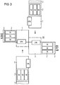
- FIG. 1 shows the different stages of the possible expansion in the order from top to bottom.
- a cabinet 1 with a central processor unit CPU is required, in addition to which a power supply cabinet with the control supply units SV, a cabinet 3 for a sub-network distributor UNV, a cabinet 4 for channel devices KAN and another cabinet 5 for service processors SKP are provided.
- These five cabinets form the basic form of a central processor unit ZE1.
- ZE2 only a further central processor unit CPU is installed in cabinet 1 for the central processor units CPU and possibly another service processor cabinet 5 is added.
- a third central processor unit CPU can be installed in the central processor unit cabinet 1 and a cabinet 4 for channel devices can be added as required.
- a fourth central processor unit CPU is now installed in the cabinet 1 for central processor units, so that this cabinet 1 is now fully equipped, while in the fifth stage of the expansion, for example, two central units ZE3 are now diametrically opposite in one direction, however with the cabinets 1 of the central processor units CPU standing side by side, are built. In this case, three central processor units CPU in the central processor unit cabinet 1.
- two central units of the fourth stage ZE4 can be arranged side by side in series, while in the seventh stage three central units of the fourth stage ZE4 are already arranged, with another central unit of the fourth stage ZE4 being added to the previous stage. Overall, this expansion level already gives you twelve times the performance.
- the power is then increased sixteen times, with four central units ZE4 now being set up in a cross shape so that the cabinets 1 of the central processor units form the intersection of this cross-shaped system.
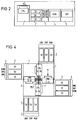
- FIG. 2 shows a basic model of the first expansion stage (ZE1) in detail.
- the central processor units in the central processor cabinet 1 are offset to the rear so that they protrude beyond the rear wall of the cabinet 1. For transport, they are provided with a protective grille SG, which can be removed during assembly. This gives the front part of the cabinet a free space.
- This central processor unit cabinet 1 is then followed by the power supply cabinet 2, each with three power supply devices SV. It is followed again by the subnetwork distribution cabinet 3 and the cabinets 4, 5 for the channel devices KAN and the service processor SKP.
- the detail image according to FIG. 3 shows two central units which are already in the end position in a horizontal shape and two further central units ZE4 which are not yet in the final installed state.
- FIG. 4 all four central units ZE4 are already shown in the final state of construction. It can be seen that the rear parts of the central processor units CPU protrude into the respective free spaces of the adjacent central processor unit cabinet 1. To do this, you must: Place the covers of the cabinets are removed and at the same time the vertical scaffold spar of two basic models are removed.
- the illustration according to FIG. 4 also shows a variant of FIG. 3, since in this figure the current supply lines I and the water supply lines H2O are made at the center of the intersection.
- FIG. 5 shows a perspective view of the cupboards arranged in a cross shape.
Landscapes
- Engineering & Computer Science (AREA)
- Theoretical Computer Science (AREA)
- Computer Hardware Design (AREA)
- Physics & Mathematics (AREA)
- General Engineering & Computer Science (AREA)
- General Physics & Mathematics (AREA)
- Power Engineering (AREA)
- Human Computer Interaction (AREA)
- Mathematical Physics (AREA)
- Software Systems (AREA)
- Multi Processors (AREA)
Abstract
Die Erfindung bezieht sich auf ein modulares Aufbausystem für Großrechner, deren Funktionseinheiten wie Zentralprozessoreinheiten (CPU), Stromversorgung (SV), Unternetzverteiler (UNV), Kanaleinrichtungen (KAN) und Serviceprozessoren (SPK), in jeweils eigenen Schränken (1...5) untergebracht sind, die nebeneinander in einer Reihe angeordnet sind und jeweils eine Zentraleinheit (ZE) bilden.
Große Rechnerleistungen werden in zunehmendem Maße durch Bildung von Multiprozessorsystemen erzeugt. Unter dem Aspekt einer stufenweisen Anpassung an den Kundenleistungsbedarf ist es notwendig, dieser Tatsache auch konstruktiv Rechnung zu tragen. Hierfür sieht die Erfindung vor, daß die Schränke (1...5) eine quadratische Grundform aufweisen und jeweils vier Zentraleinheiten (ZE) in Kreuzform angeordnet werden. Die Zentralprozessoreinheiten (CPU) in den dazugehörigen Schränken (1) sind dabei soweit nach hinten versetzt und rückseitig teilweise herausragend angeordnet, daß sich bei Aufstellen der Zentraleinheiten (ZE) in Kreuzform die Schränke (1) der Zentralprozessoreinheiten (CPU) paarweise diametral gegenüber liegen und teilweise mit ihrem rückwärtig überstehenden Teil in einem vorgesehenen Freiraum des jeweils benachbarten Zentralprozessoreinheitenschrankes (1) hineinragen.
Description
- Die Erfindung betrifft ein modulares Aufbausystem für Großrechner, deren Funktionseinheiten, wie Zentralprozessoreinheiten, Stromversorgung, Unternetzverteiler, Kanaleinrichtungen und Serviceprozessoren, in jeweils eigenen Schränken untergebracht sind, die jeweils nebeneinander in einer Reihe angeordnet sind und eine Zentraleinheit bilden.
- Aufgabe der vorliegenden Erfindung ist es, ein modulares Aufbausystem für Großrechner zu schaffen, das stufenweise an den Leistungsbedarf anpaßbar ist, wobei die Länge der internen Leitungsverbindungen ein Minimum sein soll.
- Zur Lösung dieser Aufgabe sieht die Erfindung vor, daß die Schränke eine quadratische Grundform aufweisen, daß die Zentralprozessoreinheiten in den dazugehörigen Schränken soweit nach hinten versetzt und rückseitig teilweise herausragend angeordnet sind, daß sich beim Aufstellen der Zentraleinheiten in Kreuzform die Schränke der Zentraleinheiten paarweise diametral gegenüberliegen und teilweise mit ihrem rückwärtig überstehenden Teil in den so entstandenen Freiraum des jeweils benachbarten Zentralprozessoreinheitenschrankes hineinragen.
- Durch diese Maßnahmen wird ein modulares Aufbausystem geschaffen, durch das der stufenweise Ausbau der Zentraleinheiten an den jeweiligen Leistungsbedarf in einfacher Weise ermöglicht wird. Die Leitungslänge der internen Logikverbindungen wird gegenüber einem herkömmlichen Aufbau erheblich reduziert.
- Anhand der Ausführungsbeispiele nach den FIG 1 bis 5 wird die Erfindung näher erläutert. Es zeigen
- FIG 1 eine Übersicht über die möglichen Ausbaustufen,
- FIG 2 ein Grundmodell der ersten Ausbaustufe,
- FIG 3 eine Detaildarstellung im Zentralprozessoreinheitenbereich eines voll ausgebauten Systems,
- FIG 4 eine Variante nach FIG 3,
- FIG 5 eine perspektivische Darstellung eines voll ausgebauten Systems.
- FIG 1 zeigt in der Reihenfolge von oben nach unten die unterschiedlichen Stufen des möglichen Ausbaus. In der ersten Stufe ist lediglich ein Schrank 1 mit einer Zentralprozessoreinheit CPU nötig, neben dem ein Stromversorgungsschrank mit den Steuerversorgungseinheiten SV, ein Schrank 3 für einen Unternetzverteiler UNV, ein Schrank 4 für Kanaleinrichtungen KAN und ein weiterer Schrank 5 für Serviceprozessoren SKP vorgesehen ist. Diese fünf Schränke bilden die Grundform einer Zentralprozessoreinheit ZE1. In der zweiten Stufe des Ausbaus (ZE2) wird lediglich im Schrank 1 für die Zentralprozessoreinheiten CPU eine weitere Zentralprozessoreinheit CPU eingebaut und eventuell ein weiterer Serviceprozessorschrank 5 hinzugefügt. In der dritten Stufe des Ausbaus (ZE3) läßt sich eine dritte Zentralprozessoreinheit CPU in den Zentralprozessoreinheitsschrank 1 einbauen und je nach Bedarf ein Schrank 4 für Kanaleinrichtungen hinzufügen. In der vierten Ausbaustufe (ZE4) wird nunmehr eine vierte Zentralprozessoreinheit CPU in den Schrank 1 für Zentralprozessoreinheiten eingebaut, so daß nunmehr dieser Schrank 1 voll bestückt ist, während in der fünften Stufe des Ausbaus nun beispielsweise zwei Zentraleinheiten ZE3 diametral gegenüberliegend in einer Richtung, jedoch mit den Schränken 1 der Zentralprozessoreinheiten CPU nebeneinandere stehend, aufebaut sind. Dabei sind in diesem Fall jeweils drei Zentralprozessoreinheiten CPU im Zentralprozessoreinheitenschrank 1 vorhanden. In der sechsten Aufbaustufe können zwei Zentraleinheiten der vierten Ausbaustufe ZE4 nebeneinander in Reihe angeordnet sein, während in der siebten Ausbaustufe nunmehr bereits drei Zentraleinheiten der vierten Stufe ZE4 angeordnet sind, wobei zur vorhergehenden Ausbaustufe senkrecht dazu eine weitere Zentraleinheit der vierten Ausbaustufe ZE4 hinzugefügt wird. Insgesamt erhält man bei dieser Ausbaustufe bereits die zwölffache Leistung. In der letzten Ausbaustufe wird dann die Leistung versechzehnfacht, wobei nunmehr vier Zentraleinheiten ZE4 in Kreuzform so aufgestellt sind, daß die Schränke 1 der Zentralprozessoreinheiten den Kreuzungspunkt dieser kreuzförmigen Anlage bilden.
- In FIG 2 ist ein Grundmodell der ersten Ausbaustufe (ZE1) im Detail dargestellt. Die Zentralprozessoreinheiten im Zentralprozessorschrank 1 sind nach hinten versetzt, so daß sie über die Rückwand des Schrankes 1 hinausragen. Für den Transport sind sie mit einem Schutzgitter SG versehen, das beim Zusammenbau abgenommen werden kann. Der vordere Teil des Schrankes erhält damit einen Freiraum. Diesem Zentralprozessoreinheitenschrank 1 schließt sich dann der Stromversorgungsschrank 2 mit jeweils drei Stromversorgungseinrichtungen SV an. Ihm folgt wieder der Unternetzverteilerschrank 3 sowie die Schränke 4, 5 für die Kanaleinrichtungen KAN und den Serviceprozessor SKP.
- Das Detailbild nach FIG 3 zeigt zwei bereits in der Endposition stehende Zentraleinheiten in waagrechter Form und dazu senkrecht zwei weitere Zentraleinheiten ZE4, die sich noch nicht im endgültigen Einbauzustand befinden.
- In FIG 4 sind dann alle vier Zentraleinheiten ZE4 bereits im endgültigen Aufbauzustand dargestellt. Man erkennt, daß die rückwärtigen Teile der Zentralprozessoreinheiten CPU in die jeweiligen Freiräume des benachbarten Zentralprozessoreinheitenschrankes 1 hineinragen. Zu diesem Zweck müssen an dieser Stelle die Abdeckungen der Schränke abgenommen werden und gleichzeitig der vertikale Gerüstholm zweier Grundmodelle entfernt werden. Die Darstellung nach FIG 4 zeigt außerdem insofern eine Variante zu FIG 3, da bei dieser Figur im Kreuzungsmittelpunkt die Stromzuführungen I und die Wasserzuführungen H2O vorgenommen werden.
- Eine perspektivische Darstellung der in Kreuzform angeordneten Schränke zeigt die FIG 5.
Claims (1)
- Modulares Aufbausystem für Großrechner, deren Funktionseinheiten, wie Zentralprozessoreinheiten, Stromversorgung, Unternetzverteiler, Kanaleinrichtungen und Serviceprozessoren, in jeweils eigenen Schränken untergebracht sind, die jeweils nebeneinander in einer Reihe angeordnet sind und eine Zentraleinheit bilden, dadurch gekennzeichnet, daß die Schränke (1...5) eine quadratische Grundform aufweisen, daß die Zentralprozessoreinheiten (CPU) in den dazugehörigen Schränken (1) soweit nach hinten versetzt und rückseitig teilweise herausragend angeordnet sind, daß sich beim Aufstellen der Zentaleinheiten (ZE) in Kreuzform die Schränke (1) der Zentraleinheiten (CPU) paarweise diametral gegenüberliegen und teilweise mit ihrem rückwärtig überstehenden Teil in den so entstandenen Freiraum des jeweils benachbarten Zentralprozessoreinheitenschrankes (1) hineinragen.
Applications Claiming Priority (2)
| Application Number | Priority Date | Filing Date | Title |
|---|---|---|---|
| DE9103503U DE9103503U1 (de) | 1991-03-21 | 1991-03-21 | Modulares Aufbausystem für Großrechner |
| DE9103503U | 1991-03-21 |
Publications (2)
| Publication Number | Publication Date |
|---|---|
| EP0504668A2 true EP0504668A2 (de) | 1992-09-23 |
| EP0504668A3 EP0504668A3 (en) | 1992-10-28 |
Family
ID=6865549
Family Applications (1)
| Application Number | Title | Priority Date | Filing Date |
|---|---|---|---|
| EP19920103774 Withdrawn EP0504668A3 (en) | 1991-03-21 | 1992-03-05 | Modular building system for mainframes |
Country Status (3)
| Country | Link |
|---|---|
| US (1) | US5253141A (de) |
| EP (1) | EP0504668A3 (de) |
| DE (1) | DE9103503U1 (de) |
Cited By (1)
| Publication number | Priority date | Publication date | Assignee | Title |
|---|---|---|---|---|
| CN108762422A (zh) * | 2018-06-06 | 2018-11-06 | 萍乡学院 | 一种会计报表处理装置及方法 |
Families Citing this family (7)
| Publication number | Priority date | Publication date | Assignee | Title |
|---|---|---|---|---|
| US5684671A (en) * | 1995-08-22 | 1997-11-04 | Sequent Computer Systems, Inc. | Packaging architecture for a data server |
| US6137686A (en) * | 1998-04-10 | 2000-10-24 | Casio Computer Co., Ltd. | Interchangeable modular arrangement of computer and accessory devices |
| DE10061854C2 (de) * | 2000-12-12 | 2002-11-14 | Testo Gmbh & Co Kg | Modul für Messzwecke |
| US8738832B1 (en) | 2009-06-30 | 2014-05-27 | International Business Machines Corporation | Microgrid apparatus with central area containing plural processors communicating via respective wireless connection point or bi-directional bus with module in docking bays defined by radial arms |
| US9154362B1 (en) | 2009-08-14 | 2015-10-06 | International Business Machines Corporation | Macro grid governance and communication |
| US8664911B1 (en) | 2009-10-30 | 2014-03-04 | International Business Machines Corporation | Micro grid bridge structures |
| US8180999B1 (en) | 2010-02-03 | 2012-05-15 | International Business Machines Corporation | Vertically tiered horizontally expandable micro grid system with bridge docking bay contoured by radial arms extending from central hub for coupling processor or power hubs |
Family Cites Families (6)
| Publication number | Priority date | Publication date | Assignee | Title |
|---|---|---|---|---|
| US3443161A (en) * | 1967-04-18 | 1969-05-06 | Applied Dynamics Inc | Computer circuits |
| JPS5814684B2 (ja) * | 1979-06-08 | 1983-03-22 | 富士通株式会社 | 電子機器筐体の連結構造 |
| US4423465A (en) * | 1981-09-30 | 1983-12-27 | Teng Ching Weng | Combination electronic circuit element with multidirectionally adjustable joints |
| AU580737B2 (en) * | 1983-07-18 | 1989-02-02 | Data General Corporation | Modular computer system |
| US4680674A (en) * | 1984-07-16 | 1987-07-14 | Moore Fergus E | Modular computer system with integral electronic bus |
| JPS61112503A (ja) * | 1984-11-06 | 1986-05-30 | 株式会社東芝 | 閉鎖配電盤 |
-
1991
- 1991-03-21 DE DE9103503U patent/DE9103503U1/de not_active Expired - Lifetime
-
1992
- 1992-02-24 US US07/840,163 patent/US5253141A/en not_active Expired - Fee Related
- 1992-03-05 EP EP19920103774 patent/EP0504668A3/de not_active Withdrawn
Cited By (1)
| Publication number | Priority date | Publication date | Assignee | Title |
|---|---|---|---|---|
| CN108762422A (zh) * | 2018-06-06 | 2018-11-06 | 萍乡学院 | 一种会计报表处理装置及方法 |
Also Published As
| Publication number | Publication date |
|---|---|
| US5253141A (en) | 1993-10-12 |
| EP0504668A3 (en) | 1992-10-28 |
| DE9103503U1 (de) | 1991-06-20 |
Similar Documents
| Publication | Publication Date | Title |
|---|---|---|
| EP0888706B1 (de) | Speicherprogrammierbare steuerung | |
| DE2911065A1 (de) | Wandsystem | |
| EP0129695A1 (de) | Bausystem für ein Gestell der Vertikalbauweise | |
| DE20107472U1 (de) | Trägerkonstruktion für Gegenstände allgemeiner Art | |
| DE3620379C2 (de) | ||
| EP0504668A2 (de) | Modulares Aufbausystem für Grossrechner | |
| DE10148470A1 (de) | Vorrichtung und Verfahren zum elektrischen und mechanischen Verbinden von Komponenten eines Automatisierungssystems | |
| DE7616383U1 (de) | Verbinder fuer holzbalken | |
| DE3019224A1 (de) | Verbindungsanordnung fuer gehaeuse elektronischer geraete | |
| DE69224781T2 (de) | Schrankrahmen, insbesondere für elektrische Aggregate, entsprechender Schrank | |
| DE9104134U1 (de) | Verbessertes vertikales Sortiersystem | |
| DE3411619C2 (de) | ||
| DE1066238B (de) | Fernmelde , insbesondere Fernsprechanlage mit einem Gestellreihen block aus mehreren Gestellreihen | |
| EP0458832B1 (de) | Gerätesystem mit einem ersten und wenigstens einem daran ankuppelbaren zweiten elektrischen gerät | |
| DE3112718C2 (de) | Bausatz für Schalt- und/oder Steuerschrank | |
| DE60006369T2 (de) | Kasten für elektrische akkumulatoreinheit | |
| DE29701401U1 (de) | Elektronisches Gerät | |
| DE69308455T2 (de) | Ein verdeckt angeordnetes Scharnier für ein Paneel einer Schalttafel | |
| DE3331035A1 (de) | Elektronische steuer- oder regelvorrichtung | |
| EP0471995A2 (de) | Schrank zur Aufnahme von elektrischen Baugruppenträgern | |
| DE3128376A1 (de) | Module gebaeudestruktur | |
| DE69505222T2 (de) | Einschub für elektronische Karten | |
| DE8703449U1 (de) | Steuer- und Regelgerät, insbesondere für Heizungsanlagen | |
| DE8905361U1 (de) | Codiervorrichtung für auf eine Rückwandverdrahtung aufsteckbare elektrische Baugruppe | |
| DE2755811A1 (de) | Mehretagiges gekapseltes schaltfeld mit ventilationseinrichtung |
Legal Events
| Date | Code | Title | Description |
|---|---|---|---|
| PUAI | Public reference made under article 153(3) epc to a published international application that has entered the european phase |
Free format text: ORIGINAL CODE: 0009012 |
|
| PUAL | Search report despatched |
Free format text: ORIGINAL CODE: 0009013 |
|
| AK | Designated contracting states |
Kind code of ref document: A2 Designated state(s): AT BE CH DE FR GB IT LI NL |
|
| AK | Designated contracting states |
Kind code of ref document: A3 Designated state(s): AT BE CH DE FR GB IT LI NL |
|
| 17P | Request for examination filed |
Effective date: 19921124 |
|
| STAA | Information on the status of an ep patent application or granted ep patent |
Free format text: STATUS: THE APPLICATION IS DEEMED TO BE WITHDRAWN |
|
| 18D | Application deemed to be withdrawn |
Effective date: 19941001 |