EP0503278A1 - Verfahren und Vorrichtung zur Herstellung von optischen Strukturen in Platten - Google Patents
Verfahren und Vorrichtung zur Herstellung von optischen Strukturen in Platten Download PDFInfo
- Publication number
- EP0503278A1 EP0503278A1 EP92102123A EP92102123A EP0503278A1 EP 0503278 A1 EP0503278 A1 EP 0503278A1 EP 92102123 A EP92102123 A EP 92102123A EP 92102123 A EP92102123 A EP 92102123A EP 0503278 A1 EP0503278 A1 EP 0503278A1
- Authority
- EP
- European Patent Office
- Prior art keywords
- plate
- holding bodies
- cavities
- holding members
- plates
- Prior art date
- Legal status (The legal status is an assumption and is not a legal conclusion. Google has not performed a legal analysis and makes no representation as to the accuracy of the status listed.)
- Withdrawn
Links
- 238000000034 method Methods 0.000 title claims abstract description 15
- 230000003287 optical effect Effects 0.000 title claims abstract description 8
- 150000003839 salts Chemical class 0.000 claims abstract description 28
- 238000005342 ion exchange Methods 0.000 claims abstract description 14
- 238000010438 heat treatment Methods 0.000 claims abstract description 9
- 238000005520 cutting process Methods 0.000 claims description 10
- 238000006073 displacement reaction Methods 0.000 claims description 10
- 238000004519 manufacturing process Methods 0.000 claims description 4
- 230000005684 electric field Effects 0.000 claims description 3
- 238000003780 insertion Methods 0.000 claims description 3
- 230000037431 insertion Effects 0.000 claims description 3
- 230000005540 biological transmission Effects 0.000 claims description 2
- 238000007789 sealing Methods 0.000 abstract description 2
- 239000011521 glass Substances 0.000 description 30
- 230000008646 thermal stress Effects 0.000 description 4
- 229910001369 Brass Inorganic materials 0.000 description 3
- 239000010951 brass Substances 0.000 description 3
- 239000000919 ceramic Substances 0.000 description 3
- 239000000155 melt Substances 0.000 description 3
- 239000002184 metal Substances 0.000 description 3
- 229910052751 metal Inorganic materials 0.000 description 3
- 238000003860 storage Methods 0.000 description 3
- 229910000669 Chrome steel Inorganic materials 0.000 description 2
- 230000017525 heat dissipation Effects 0.000 description 2
- 239000007788 liquid Substances 0.000 description 2
- 239000000758 substrate Substances 0.000 description 2
- 229910052782 aluminium Inorganic materials 0.000 description 1
- XAGFODPZIPBFFR-UHFFFAOYSA-N aluminium Chemical compound [Al] XAGFODPZIPBFFR-UHFFFAOYSA-N 0.000 description 1
- 239000004020 conductor Substances 0.000 description 1
- 238000001816 cooling Methods 0.000 description 1
- 230000009193 crawling Effects 0.000 description 1
- 230000001419 dependent effect Effects 0.000 description 1
- 238000009826 distribution Methods 0.000 description 1
- 238000010292 electrical insulation Methods 0.000 description 1
- 238000005265 energy consumption Methods 0.000 description 1
- 230000009191 jumping Effects 0.000 description 1
- 230000005855 radiation Effects 0.000 description 1
- 230000001105 regulatory effect Effects 0.000 description 1
- 230000035882 stress Effects 0.000 description 1
Images



Classifications
-
- G—PHYSICS
- G02—OPTICS
- G02B—OPTICAL ELEMENTS, SYSTEMS OR APPARATUS
- G02B6/00—Light guides; Structural details of arrangements comprising light guides and other optical elements, e.g. couplings
- G02B6/10—Light guides; Structural details of arrangements comprising light guides and other optical elements, e.g. couplings of the optical waveguide type
- G02B6/12—Light guides; Structural details of arrangements comprising light guides and other optical elements, e.g. couplings of the optical waveguide type of the integrated circuit kind
- G02B6/13—Integrated optical circuits characterised by the manufacturing method
- G02B6/134—Integrated optical circuits characterised by the manufacturing method by substitution by dopant atoms
- G02B6/1345—Integrated optical circuits characterised by the manufacturing method by substitution by dopant atoms using ion exchange
-
- C—CHEMISTRY; METALLURGY
- C03—GLASS; MINERAL OR SLAG WOOL
- C03C—CHEMICAL COMPOSITION OF GLASSES, GLAZES OR VITREOUS ENAMELS; SURFACE TREATMENT OF GLASS; SURFACE TREATMENT OF FIBRES OR FILAMENTS MADE FROM GLASS, MINERALS OR SLAGS; JOINING GLASS TO GLASS OR OTHER MATERIALS
- C03C21/00—Treatment of glass, not in the form of fibres or filaments, by diffusing ions or metals in the surface
- C03C21/001—Treatment of glass, not in the form of fibres or filaments, by diffusing ions or metals in the surface in liquid phase, e.g. molten salts, solutions
-
- C—CHEMISTRY; METALLURGY
- C03—GLASS; MINERAL OR SLAG WOOL
- C03C—CHEMICAL COMPOSITION OF GLASSES, GLAZES OR VITREOUS ENAMELS; SURFACE TREATMENT OF GLASS; SURFACE TREATMENT OF FIBRES OR FILAMENTS MADE FROM GLASS, MINERALS OR SLAGS; JOINING GLASS TO GLASS OR OTHER MATERIALS
- C03C21/00—Treatment of glass, not in the form of fibres or filaments, by diffusing ions or metals in the surface
- C03C21/001—Treatment of glass, not in the form of fibres or filaments, by diffusing ions or metals in the surface in liquid phase, e.g. molten salts, solutions
- C03C21/002—Treatment of glass, not in the form of fibres or filaments, by diffusing ions or metals in the surface in liquid phase, e.g. molten salts, solutions to perform ion-exchange between alkali ions
- C03C21/003—Treatment of glass, not in the form of fibres or filaments, by diffusing ions or metals in the surface in liquid phase, e.g. molten salts, solutions to perform ion-exchange between alkali ions under application of an electrical potential difference
Definitions
- EP-A-0 326 920 discloses a device for producing optical structures such as waveguides in plane-parallel glass plates. Thereby, zones with increased refractive index as optical waveguides or the like are to be generated in the plane-parallel glass plates by ion exchange from a salt melt.
- the plate provided with a mask is clamped between two metal holding bodies.
- the holding bodies form cavities on both sides of the plate, which are open towards the plate.
- the cavities are surrounded by closed sealing surfaces that lie against the plate.
- Storage tanks for molten salt are connected to the lower ends of the cavities via filling feed lines. Vent lines exit from the upper ends of the cavities.
- the cavities are bores of the holding bodies which are open at the top.
- the holding bodies are clamped together with the plate by a clamping device which contains disc springs.
- the entire arrangement must be brought to a fairly high temperature at which the molten salt is liquid and the ion exchange takes place. There should be practically no local heat dissipation on the glass plate, because otherwise tension will occur in the glass plate and the glass plate will crack.
- the publication contains no disclosure of how this is to be accomplished. In practice, the arrangement described in the document is placed in an oven and slowly heated up to the desired temperature at which the salt introduced into the storage container melts. For changing the glass plates the furnace and the entire arrangement must then be cooled again so that the clamping device can be released and the treated plate can be replaced by a new untreated plate. This closest procedure is quite lengthy.
- the invention is based on the object of designing a method of the type defined at the outset and an apparatus for carrying out the method in such a way that the time required for producing an optical structure on a substrate is significantly reduced compared to the known method.
- the method should be designed so that it can be automated in a simple manner.
- the method according to the invention can also be easily automated.
- the holding bodies can, according to the invention, be directly heated by heating elements seated in the holding bodies.
- the holding bodies are surrounded by a heat-insulating housing which has an insertion slot for inserting and removing the plates in the area between the holding bodies and transversely to their direction of adjustment.
- the holding bodies can be moved apart and moved together by means of an adjusting device arranged outside the housing, via transmission members guided through the housing wall.
- the gripping device attacks the plates by means of cutting edges on opposite sides.
- Embodiments of the device are the subject of further dependent claims.
- a heat-insulating housing 12 sits on a frame 10.
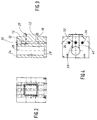
- Two holding bodies 14 and 16 are arranged in the housing 12. Such a holding body 14 is shown in detail in FIGS. 2 to 4.
- the holding body 14 is essentially cuboid.
- a rectangular projection 18 is provided on its vertical surface 16 facing the plate.
- a substantially rectangular seal 20 running along the edge of the projection 18 forms a cavity 22 within the seal 20.
- a blind hole 26 of relatively large diameter extends from the upper side 24 of the holding body 14 to close to the lower side 28. Between the blind hole 26 and the surface 16, three bores 30, 32 and 34 of relatively small diameter are provided parallel to the surface 16. These holes 30, 32 and 34 receive heating elements 36 (Fig.3).
- the holding bodies 14 and 16 are heated directly by these heating elements 36.
- the holding body 14 and 16 consist of a good heat-conducting material such as aluminum. This ensures a uniform temperature distribution in the entire holding body 14 or 16.
- a pair of inlet bores or outlet bores 38 and 40 extend in a horizontal plane from the lower edge of the cavity 22 to the blind hole 26.
- the inlet bores or outlet bores 38 and 40 run between the bores 30 and 32 or 32 and 34.
- the holding body 16 is designed in the same way as the holding body 14 but is rotated by 180 °.
- the blind hole 26 is used in each holding body 14 and 16 as a reservoir for a molten salt, which is used for the ion exchange.
- Each of the holding bodies sits on a pair of square tubes 42. Only one of these square tubes can be seen in FIG.
- the ends of the square tubes 42 are passed through the end walls of the housing 12 and are mounted on ceramic rollers 44 and 46. Because of this everyone is Holding body guided in a straightforward manner.
- This arrangement has the advantage that the holding bodies 14 and 16 are guided outside the heat-insulating housing 12 practically at room temperature.
- the hot molten salt has the unpleasant property of "crawling". You could then easily reach a storage provided within the housing 12 and impair the mobility of the holding body 14 and 16. However, the melt cannot reach the ceramic rollers 44 and 46 since it would have solidified before it got there.
- the holding bodies 14 and 16 can be moved apart and moved together by pneumatic cylinders 48 and 50, respectively.
- the pneumatic cylinders 48 and 50 are also arranged outside the housing 12.
- the stroke movement of the pneumatic cylinders 48 and 50 is transmitted to the holding bodies via push rods 52 and 54, respectively.
- the push rods 52 and 54 are made of chrome steel because of its poor thermal conductivity.
- the push rods 52 and 54 are passed through brass blocks 56 and 58, respectively.
- On the push rod 52 there are adjustable nuts 60 and 62 on both sides of the brass block 56.
- On the push rod 54 there are adjustable nuts 64 and 66 on both sides of the brass block 58.
- the nuts 60, 62, 64 and 66 limit the stroke of the pneumatic cylinders 48 and 50 and thus the holding bodies 14 and 16.
- pneumatic cylinders 48 and 50 as servomotors allows the force with which the holding bodies 14 and 16 bear against the plate to be regulated sensitively via the pressure.
- the pressure must be so great that the cavities 22 are tight when the holding bodies 14 and 16 abut against a plate for the melt, but on the other hand the plate is not pressed unnecessarily strongly and is possibly damaged.
- melt leakage was observed with a surface pressure of 0.5 N / mm2 prevented. A pressure force of 500 N was required for this.
- the housing 12 has two openings 68 and 70 on the upper side. These openings 68 and 70 are essentially aligned with the blind holes 26 (FIGS. 3 and 4) of the holding bodies 14 and 16. Through the openings 68 and 70, tension members 72 and 74 protrude, on which displacement bodies 76 and 78 hang. The displacement bodies 76 and 78 are guided with play in the blind holes 22 of the holding bodies 14 and 16, respectively.
- FIG. 5 A lifting and lowering device for such a displacement body is shown in FIG. 5 on an enlarged scale.
- the lifting and lowering device contains a pneumatic cylinder 80.
- the pneumatic cylinder 80 is seated with a vertical axis in a holder 82.
- 84 denotes a piston rod of the pneumatic cylinder 80.
- a swivel head 86 is pivotally mounted about the vertical axis via ball bearings 88 and 90.
- a horizontal arm 92 is seated in the swivel head.
- the displacement body 76 is attached to the end of the arm 92 via the tension member 72.
- the tension member 72 carries a pin 94 at its upper end.
- the pin 94 is connected to the boom 92 via a bushing 96 made of hard tissue, which is seated in a bore 98 in the end face of the boom 92.
- the displacement body 76 is electrically insulated from the arm 92 and the lifting and lowering device.
- the pivotability of the arm 92 with the ball-bearing pivot head 86 allows the displacement body 76 to follow the movements of the holding body 14.
- the lower part of the pneumatic cylinder 80 is filled with oil. This ensures a slow and jerk-free lowering. Oil is easier to throttle than air.
- the pneumatic cylinder 80 makes such a stroke that it lifts the displacement body from the bottom of the blind hole 26 to the inlet bores or outlet bores 38, 40.
- the housing 12 also has a slot 100 on the upper side.
- the slot 100 extends transversely to the stroke direction of the holding bodies 14 and 16 approximately in the plane of symmetry between the holding bodies 14 and 16.
- a plane-parallel plate to be treated usually a glass plate, can be brought into a position between the holding bodies 14 and 16 and pulled out after treatment. This is done by means of a gripping device, which is shown in detail in Figures 6 to 8.
- the gripping device is guided on a column 102 so that it can move vertically.
- a guide column 104 of smaller diameter secures the gripping device against rotation.
- the guide column 104 is shorter than the column 102.
- the gripping device has a handle part 106.
- the handle part 106 is guided with corresponding bores on the column 102 and the guide column 104 so as to be vertically displaceable.
- the grip part 106 has a further bore 108.
- the handle part 106 can be lifted up over the upper end of the guide column 104 and then pivoted.
- the handle part 106 can then be lowered again in a defined, pivoted angular position, the guide column 104 then being guided in the bore 108.
- a cross member 110 is seated on the handle part 106.
- Two parallel rods 112 and 114 extend downward from the end of the cross member 110.
- At the bottom of the bars sits a Crosspiece 116.
- Two L-shaped gripping jaws 118 and 120 are articulated on the crosspiece 116 about pivot axes 122 and 124, respectively.
- the gripping jaws 118 and 120 have mutually directed, essentially horizontal legs 126 and 128 and essentially vertically downwardly directed legs 130 and 132.
- An actuating rod 134 extends parallel to the rods 112 and 114 between them through an opening 136 in the cross member 110 downward.
- a double-T-shaped end piece 138 sits on the actuating rod 134.
- the end piece has two mutually opposing arms 140 and 142 with horizontal, U-shaped cutouts 144 and 146, respectively.
- the cutouts 144 and 146 engage around a pin 148 and 150, respectively the inner ends of the legs 126 and 128 of the gripping jaws 118 and 120.
- the actuating rod 134 is articulated with its upper end to an arm 152 of an angle lever 154.
- the angle lever 154 is pivotally mounted on the cross member 110 about a pivot axis 156.
- a connecting rod 160 is articulated on the second arm 158 of the bell crank.
- the opposite end of the connecting rod 160 is articulated on an actuating lever 162 which is mounted on the crossbar 110 so as to be pivotable about an axis 164.
- a tension spring 166 is attached on the one hand to the cross member 110 and on the other hand to the connecting rod 160.
- the tension spring 166 therefore pulls the connecting rod to the left in FIG. 6. It thus pivots the angle lever 154 counterclockwise in FIG. 6 and thereby tries to move the arm 152 and the actuating rod 134 upwards.
- the gripping jaw 118 is moved counterclockwise and the gripping jaw 120 is moved clockwise.
- the tension spring 166 thus tries to hold the gripping device in the closed position.
- the tensile force of the tension spring 166 determines the pressure force.
- the gripping device can be opened against the action of the tension spring 166 via the actuating lever 162.
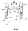
- the lower cross part 170 of the double-T-shaped end piece 138 carries a stop 172 for the glass plate 174 to be gripped.
- the stop 172 is formed by a sheet metal strip which is fastened to the cross part and whose ends are bent down at right angles and two at a distance mutually arranged, parallel, sharp cutting edges 176 and 178 form. The upper edge of the glass plate 174 bears against these cutting edges 176 and 178.
- Gripping pieces 180 and 182 are attached to the legs 130 and 132 of the gripping jaws 118 and 120 which project downwards.
- the gripping pieces 180 and 182 are sheet metal parts which, like the stop 172, each form a pair of sharp cutting edges 184, 186 and 188, 190, respectively.
- the gripping pieces 180 and 182, like the stop 172, are made of poorly heat-conducting chrome steel sheet.
- the apparatus described is used as follows:
- the holding bodies 14 and 16 are heated by the heating elements 36 and are uniformly at a high temperature of, for example, 380 ° C.
- the blind holes 26 form chambers which receive a molten salt.
- a salt introduced into the blind bores 26 forms a liquid salt melt.
- the displacement bodies 76 are raised by the lifting and lowering device (FIG. 5).
- the supply of molten salt is therefore located in the lower part of the blind hole 26 below the inlet holes or outlet holes 38 and 40.
- the cavities 22 are free of molten salt. In this state, the holding bodies 14 and 16 have moved apart.
- the gripping device (FIG. 6) is raised, pivoted and lowered again, so that the grip part 106 is guided with the bore 108 on the guide column 104.
- the gripping jaws 118 and 120 are opened.
- the gripping device grips from a supply via a glass plate 174 provided with a mask.
- the gripping device is lowered so far that the stop 172 with its cutting edges 176, 178 comes to rest on the upper edge of the glass plate 174. Then the operating lever 162 is released.
- the gripping jaws 118 and 120 are moved inward by the tension spring 166 until the cutting edges 184, 186 and 188, 190 of the gripping pieces 180 and 182 lie against the side edges of the glass plate 174 under the influence of the tension spring 166.
- the glass plate is now held in the gripping device.
- the gripping device is now raised with the glass plate 174 until the grip part 106 is located above the upper end of the guide column 104. Then the glass plate 174 is securely above the top of the housing 12. The gripping device is pivoted until the handle part 106 with the other hole (as shown in FIG. 7) can slide down on the guide column 104. The alignment is then such that the gripping jaws 118, 120 with the glass pane 174 move through the slot 100 between the holding bodies 14 and 16 which have moved apart.
- the glass pane and gripping jaws are held in this position for a while until the glass pane 174 and the gripping jaws 118, 120 have essentially heated up to the temperature of the holding bodies 14 and 16 by radiant heat. This heating takes place uniformly, so that no thermal stresses occur.
- the holding bodies 14 and 16 are moved together by the pneumatic cylinders so that they hold the glass pane 174 between them with a predetermined pressure.
- the gripping jaws 118 and 120 are opened and raised and release the glass plate 174.
- the displacers 76 and 78 are lowered.
- the displacers 76 and 78 displace the molten salt from the lower part of the blind bores 26.
- the molten salt rises and flows through the inlet bores 38 and 40 into the cavities 22 directly adjacent to the surface of the glass plate.
- a field-assisted ion exchange then takes place in the usual way in the areas left free by the mask.
- a voltage is applied between the holding bodies 14 and 16.
- the holding bodies are kept insulated via the ceramic rollers 44 and 46. Electrical insulation is also provided between the push rods 52 and 54 and the holding bodies 14 and 16, respectively.
- the gripping device is lowered again.
- the gripping jaws 118 and 120 grip the glass plate 174. Only the stop 172 and the gripping pieces 180, 182 with the cutting edges 176, 178; 184, 186 and 188, 190 to the hot glass plate 174. There is practically no heat dissipation via these cutting edges, so that thermal stresses are avoided.
- the displacers 76 and 78 are raised.
- the molten salt thereby flows back from the cavities 22 via the inlet bores or outlet bores 38 and 40 into the lower sections of the blind bores 26.
- the holding bodies 14 and 16 are moved apart again by the pneumatic cylinders 48 and 50.
- the treated glass plate 174 is pulled out of the housing 12 through the slot 100. After the glass plate 174 has cooled uniformly, it is put down. A new glass plate can now be picked up and treated in the same way.
- the holding bodies 14 and 16 and the interior of the heat-insulating housing 12 are constantly at the operating temperature of e.g. Kept at 380 ° C.
Landscapes
- Chemical & Material Sciences (AREA)
- Engineering & Computer Science (AREA)
- Geochemistry & Mineralogy (AREA)
- Life Sciences & Earth Sciences (AREA)
- Physics & Mathematics (AREA)
- Chemical Kinetics & Catalysis (AREA)
- General Chemical & Material Sciences (AREA)
- Materials Engineering (AREA)
- Organic Chemistry (AREA)
- General Physics & Mathematics (AREA)
- Optics & Photonics (AREA)
- Microelectronics & Electronic Packaging (AREA)
- Surface Treatment Of Glass (AREA)
Applications Claiming Priority (2)
| Application Number | Priority Date | Filing Date | Title |
|---|---|---|---|
| DE19914108424 DE4108424C1 (enExample) | 1991-03-15 | 1991-03-15 | |
| DE4108424 | 1991-03-15 |
Publications (1)
| Publication Number | Publication Date |
|---|---|
| EP0503278A1 true EP0503278A1 (de) | 1992-09-16 |
Family
ID=6427368
Family Applications (1)
| Application Number | Title | Priority Date | Filing Date |
|---|---|---|---|
| EP92102123A Withdrawn EP0503278A1 (de) | 1991-03-15 | 1992-02-08 | Verfahren und Vorrichtung zur Herstellung von optischen Strukturen in Platten |
Country Status (2)
| Country | Link |
|---|---|
| EP (1) | EP0503278A1 (enExample) |
| DE (1) | DE4108424C1 (enExample) |
Citations (3)
| Publication number | Priority date | Publication date | Assignee | Title |
|---|---|---|---|---|
| EP0267588A1 (de) * | 1986-11-13 | 1988-05-18 | Siemens Aktiengesellschaft | Anordnung zum Haltern eines Glaskörpers |
| EP0326920A2 (de) * | 1988-02-01 | 1989-08-09 | Bodenseewerk Gerätetechnik GmbH | Vorrichtung zur Durchführung feldunterstützten Ionenaustauschs in planparallelen Platten |
| EP0356644A1 (de) * | 1988-08-09 | 1990-03-07 | Bodenseewerk Gerätetechnik GmbH | Verfahren zur Herstellung von Wellenleitern auf einem Glassubstrat durch Ionenaustausch |
-
1991
- 1991-03-15 DE DE19914108424 patent/DE4108424C1/de not_active Expired - Fee Related
-
1992
- 1992-02-08 EP EP92102123A patent/EP0503278A1/de not_active Withdrawn
Patent Citations (3)
| Publication number | Priority date | Publication date | Assignee | Title |
|---|---|---|---|---|
| EP0267588A1 (de) * | 1986-11-13 | 1988-05-18 | Siemens Aktiengesellschaft | Anordnung zum Haltern eines Glaskörpers |
| EP0326920A2 (de) * | 1988-02-01 | 1989-08-09 | Bodenseewerk Gerätetechnik GmbH | Vorrichtung zur Durchführung feldunterstützten Ionenaustauschs in planparallelen Platten |
| EP0356644A1 (de) * | 1988-08-09 | 1990-03-07 | Bodenseewerk Gerätetechnik GmbH | Verfahren zur Herstellung von Wellenleitern auf einem Glassubstrat durch Ionenaustausch |
Non-Patent Citations (1)
| Title |
|---|
| PATENT ABSTRACTS OF JAPAN vol. 12, no. 405 (C-539)26. Oktober 1988 & JP-A-63 144 147 ( CANON INC ) 16. Juni 1988 * |
Also Published As
| Publication number | Publication date |
|---|---|
| DE4108424C1 (enExample) | 1992-05-07 |
Similar Documents
| Publication | Publication Date | Title |
|---|---|---|
| DE4230807C2 (de) | Vorrichtung und Verfahren zur Substratkühlung in einer evakuierten Umgebung | |
| DE69731199T2 (de) | Verfahren und einrichtung zur berührungslose behandlung eines scheiben förmiges halbleitersubstrats | |
| DE2734419C2 (enExample) | ||
| DE2942738C2 (de) | Vorrichtung zum Biegen von Glastafeln | |
| DE3109149C2 (de) | Vorrichtung zum Formen einer flachen Glasscheibe | |
| DE2700499A1 (de) | Verfahren und vorrichtung zum biegen einer platte eines glasmaterials im erhitzten zustand | |
| DE2524315A1 (de) | Galvanisiergestell | |
| DE2730162A1 (de) | Verfahren und vorrichtung zum ziehen eines monokristallinen koerpers aus einer schmelze | |
| DE2942724C2 (de) | Vorrichtung und Verfahren zur thermischen Behandlung von Glastafeln | |
| DE3108336A1 (de) | Giessverfahren und -vorrichtung | |
| DE102014004728B4 (de) | Vorrichtung und Verfahren zum Löten von Fügepartnern | |
| DE69227521T2 (de) | Quartzglasscheibe mit grosser abmessung und hoher sauberkeit und verfahren und vorrichtung ihrer herstellung | |
| DE2824403C2 (de) | Verfahren zum Beschichten von Gegenständen, insbesondere Glasflaschen | |
| DE3939352A1 (de) | Vorrichtung zum biegen von kleinkalibrigen rohrstuecken aus thermoplastischen kunststoffen | |
| DE2659762C2 (de) | Vorrichtung zum Biegen von Glasscheiben in relativ scharfen Winkeln | |
| DE4108424C1 (enExample) | ||
| DE2035783C3 (de) | Verfahren und Vorrichtung zum AnIo ten eines Bleiprofilteiles an den verzinnten Rand einer Glasplatte unter kontrolliertem Druck und kontrollierter Temperatur | |
| EP0267588B1 (de) | Anordnung zum Haltern eines Glaskörpers | |
| DE2239101A1 (de) | Aufhaengeinrichtung fuer heisse glasscheiben | |
| DE2821656A1 (de) | Vorrrichtung zur halterung einer glasbahn beim pressbiegen | |
| EP0983809A2 (de) | Verfahren und Vorrichtung zum Biegen eines Hohlprofiles zur Herstellung eines abstandhalter-Rahmens für Isolierglasscheiben | |
| DE2350591C3 (de) | Vorrichtung zum Kühlen von erwärmten Glasscheiben für deren thermisches Vorspannen | |
| DE2132796A1 (de) | Durchsichtige,elektrisch leitende Gegenstaende und Verfahren zu deren Herstellung | |
| DE1421773B2 (de) | Verfahren und vorrichtung zum biegen von glasplatten | |
| DE1796123C3 (de) | Verfahren und Vorrichtung zum Herstellen von gebogenen Glasscheiben |
Legal Events
| Date | Code | Title | Description |
|---|---|---|---|
| PUAI | Public reference made under article 153(3) epc to a published international application that has entered the european phase |
Free format text: ORIGINAL CODE: 0009012 |
|
| AK | Designated contracting states |
Kind code of ref document: A1 Designated state(s): DE FR GB |
|
| 17P | Request for examination filed |
Effective date: 19921030 |
|
| STAA | Information on the status of an ep patent application or granted ep patent |
Free format text: STATUS: THE APPLICATION HAS BEEN WITHDRAWN |
|
| 18W | Application withdrawn |
Withdrawal date: 19930522 |