EP0503043B1 - Farbbilderzeugungsvorrichtung mit randfarbwahl - Google Patents
Farbbilderzeugungsvorrichtung mit randfarbwahl Download PDFInfo
- Publication number
- EP0503043B1 EP0503043B1 EP91917614A EP91917614A EP0503043B1 EP 0503043 B1 EP0503043 B1 EP 0503043B1 EP 91917614 A EP91917614 A EP 91917614A EP 91917614 A EP91917614 A EP 91917614A EP 0503043 B1 EP0503043 B1 EP 0503043B1
- Authority
- EP
- European Patent Office
- Prior art keywords
- border
- color
- electrostatic latent
- latent images
- image
- Prior art date
- Legal status (The legal status is an assumption and is not a legal conclusion. Google has not performed a legal analysis and makes no representation as to the accuracy of the status listed.)
- Expired - Lifetime
Links
- 238000004519 manufacturing process Methods 0.000 title claims abstract description 28
- 239000003086 colorant Substances 0.000 claims abstract description 17
- 238000000926 separation method Methods 0.000 claims abstract description 13
- 238000011161 development Methods 0.000 claims description 4
- 238000005520 cutting process Methods 0.000 description 5
- 238000003860 storage Methods 0.000 description 5
- 238000012546 transfer Methods 0.000 description 5
- 238000013459 approach Methods 0.000 description 2
- 238000009432 framing Methods 0.000 description 2
- 230000007246 mechanism Effects 0.000 description 2
- 238000012545 processing Methods 0.000 description 2
- 229910052709 silver Inorganic materials 0.000 description 2
- 239000004332 silver Substances 0.000 description 2
- -1 silver halide Chemical class 0.000 description 2
- 244000025254 Cannabis sativa Species 0.000 description 1
- 230000015572 biosynthetic process Effects 0.000 description 1
- 238000004140 cleaning Methods 0.000 description 1
- 230000006835 compression Effects 0.000 description 1
- 238000007906 compression Methods 0.000 description 1
- 238000005516 engineering process Methods 0.000 description 1
- 230000006872 improvement Effects 0.000 description 1
- 235000019239 indanthrene blue RS Nutrition 0.000 description 1
- UHOKSCJSTAHBSO-UHFFFAOYSA-N indanthrone blue Chemical compound C1=CC=C2C(=O)C3=CC=C4NC5=C6C(=O)C7=CC=CC=C7C(=O)C6=CC=C5NC4=C3C(=O)C2=C1 UHOKSCJSTAHBSO-UHFFFAOYSA-N 0.000 description 1
- 230000000873 masking effect Effects 0.000 description 1
- 239000000463 material Substances 0.000 description 1
- 238000000034 method Methods 0.000 description 1
- 238000012986 modification Methods 0.000 description 1
- 230000004048 modification Effects 0.000 description 1
- 238000010422 painting Methods 0.000 description 1
- 230000008569 process Effects 0.000 description 1
- 230000033458 reproduction Effects 0.000 description 1
- 238000012216 screening Methods 0.000 description 1
- 239000007787 solid Substances 0.000 description 1
- 239000002699 waste material Substances 0.000 description 1
Images

Classifications
-
- G—PHYSICS
- G03—PHOTOGRAPHY; CINEMATOGRAPHY; ANALOGOUS TECHNIQUES USING WAVES OTHER THAN OPTICAL WAVES; ELECTROGRAPHY; HOLOGRAPHY
- G03G—ELECTROGRAPHY; ELECTROPHOTOGRAPHY; MAGNETOGRAPHY
- G03G15/00—Apparatus for electrographic processes using a charge pattern
- G03G15/01—Apparatus for electrographic processes using a charge pattern for producing multicoloured copies
-
- Y—GENERAL TAGGING OF NEW TECHNOLOGICAL DEVELOPMENTS; GENERAL TAGGING OF CROSS-SECTIONAL TECHNOLOGIES SPANNING OVER SEVERAL SECTIONS OF THE IPC; TECHNICAL SUBJECTS COVERED BY FORMER USPC CROSS-REFERENCE ART COLLECTIONS [XRACs] AND DIGESTS
- Y10—TECHNICAL SUBJECTS COVERED BY FORMER USPC
- Y10S—TECHNICAL SUBJECTS COVERED BY FORMER USPC CROSS-REFERENCE ART COLLECTIONS [XRACs] AND DIGESTS
- Y10S347/00—Incremental printing of symbolic information
- Y10S347/90—Data processing for electrostatic recording
Definitions
- This invention relates generally to the formation of multicolor images with colored borders automatically inserted around the images.
- the receiving surface may be on an intermediate member which repeatedly brings the receiving surface into transfer relation with the consecutive images to overlay them in registration.
- the receiving surface is a receiving sheet of paper or similar material which has been secured around the periphery of a transfer roller, as described in commonly assigned U.S. Patent Application Serial No. 07/532,832 to Jamzadeh et al, filed June 4, 1990, now US-A-5 047 791, published 10.09.91.
- the present invention provides an electrostatographic color image production apparatus which forms a series of large color separation electrostatic latent images of a multicolor image on an image member.
- Each large latent image is made up of an array of smaller latent images with border regions therebetween.
- Latent images are formed in the border regions to create a border color in one of the dominant colors of the multicolor image.
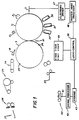
- FIG. 1 illustrates a multicolor image production apparatus utilizing electrophotography.
- An image member for example, a photoconductive drum 1
- a charging station 2 uniformly charges the surface of the drum 1.
- the uniformly charged surface is exposed at an exposure station, for example, laser exposure station 3, to create a series of electrostatic images, each representing a color separation of a multicolor image to be formed.
- the series of electrostatic images are toned by different color toner development stations 20, 21 and 22, one different color for each image, to create a series of different color toner images.
- a fourth (black) development station may be provided if desired.
- the images are then transferred in registration to a receiving sheet carried on the periphery of a transfer roller 5.
- the drum 1 is cleaned by cleaning station 6 and reused.
- the receiving sheet is fed from a receiving sheet supply 23 into a nip 10 between drum 1 and roller 5. As it approaches nip 10 it is secured to drum 5 by a vacuum means, gripping fingers or other mechanism.
- a vacuum means gripping fingers or other mechanism.
- the leading end of the sheet can be secured by a row of vacuum holes 28 and the trailing end by a row of vacuum holes 29.
- the leading edge of the receiving sheet is stripped from roller 5 by stripping mechanism 18.
- the receiving sheet is pushed by further rotation of roller 5 onto a sheet transport 24 which carries it to a fixing device 25 and then to a cutter 26. After the sheet has been cut by the cutter 26 the resulting prints are collected in a tray 27 or more sophisticated print collecting device.
- the input for exposure station 3 begins with a data source.
- the data source is a color scanner 40 which includes a color responsive CCD 41 for scanning an original to be printed, for example, 35mm color negative film.
- the output from CCD 41 is fed to a signal processor 42 which converts the CCD signal into a form suitable for storing in memory.
- signal processor 42 can use suitable compression algorithms to save on storage, enhance the image in both its color aspects and its resolution including color masking, halftone screening, etc. all processes well known in the art.
- the image information is stored in a suitable storage 43. Because this system demands substantial storage, a preferred form of storage is a system using magnetic disks.
- a logic and control 30 is capable of accessing the storage 43 and also receives inputs from various portions of the machine including encoders (not shown) on drum 1 and roller 5 and various stations to manage the timing of the entire apparatus.
- One of the inputs to logic and control 30 is a print size designation portion 45 of an operator control panel. As shown in Fig. 1, the operator can press a button beside any of four print sizes ranging in inches from, say, 4x6 through 5x7, 8x10, and 11x17.
- the logic and control 30 then receives the input from the print size designation portion 45 and the memory 43 and supplies that information in an appropriate form to raster image processor 46 which lays out the bit map for the ultimate exposure.
- the output from the raster image processor 46 is fed to an electronic driver 47 for electronic exposure station 3 to control the intensity of a laser, LED printhead, or the like, making up that station.
- Figure 3 shows an approach to positioning four 5x7 images on a 12x18 receiving sheet with borders. If the receiving sheet is cut along the dotted lines shown in Figure 3, a one-half inch border is provided for each print.
- Figure 4 illustrates two 8x10 images on a 12x18 receiving sheet. With this geometry, if the sheet is cut exactly in half the 8x10′s will have one-half inch borders on the top and bottom and 1-inch borders on the sides.
- Figure 5 shows one 11x17 print on a 12x18 with one-half inch (1,27 cm) borders on top, bottom and both sides.
- snapshots are popular without a border
- larger prints often are mounted with a border.
- the 12x18 size allows production of four 5x7′s, two 8x10′s and one 11x17 with even borders.
- the present invention provides an improvement in the selection of colors for borders produced on color copiers. This same technology can be used to permit choice of border color for each print larger than 4x6 in the apparatus shown in Figure 1, by exposing the border area uniformly for one or more of the color separations.
- the 12 inch by 18 inch size (30,48 cm by 45,72 cm) is particularly useful in the United States with the standard print sizes discussed above. Most of these sizes have been standard in the United States for printing from 35mm film for more than 40 years. However, other size receiving sheets may be optimum for other circumstances. For example, in markets in which 4x6 is not the high volume size, integer multiples of whatever that size is is a preferred starting point in determining the preferred receiving sheet size. Further, if customers prefer 4x6 snapshots with borders, then the receiving sheet could be made larger by the amount of the borders. Other arrangements could include a combination of different size prints from the same receiving sheet, for example, seven 4x6 prints and one 5x7. All of this is well within the skill of the art within the general framework of this description.
- slitting, chopping or cutting arts are extremely well developed. Devices are presently available that can be set to slit or cut any sheet at a variety of locations. However, a medium volume photofinishing operation may install a less expensive automatic cutting device that cuts only a single high volume print, for example, 4x6 snapshots and allows all other sizes to be trimmed by hand. In such a device the cutter 26 would be either disablable or there would be a path around it for sizes larger than the high volume size.
- printed margins are electronically added around images that do not fill the frame, in part to uniformly fatigue the photoconductor and in part to enhance different features of the image by automatically selecting colors for the border according to first, second, third, etc. most dominant colors of the image.
- One option for the selection of the color for the border is to use either the first, second, third, etc. most dominant color in the print or a multiple color border of some combination of these colors.
- CCD 41 of color scanner 40 is fed to signal processor 42 in three (red, green, and blue) channels.
- Each pixel will have a value for each of the three channels of, say, from 0 to 255 for an eight-bit signal.
- a purely red pixel will have values R (red) up to 255, G (green) equals 0, and B (blue) equals 0.
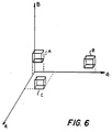
- the volume defined by the coordinate axes of Figure 6 is divided into a plurality of rectilinear solid areas (boxes) three of which ("A", "B", and "C") are shown in Figure 6.
- boxes three of which ("A", "B", and "C" are shown in Figure 6.
- A rectilinear solid areas
- B rectilinear solid areas
- C rectilinear solid areas
- Every position for the entire volume of the coordinate system falls into one box, only three of which are represented in Figure 6.
- Each pixel of the image is considered, and the number of pixels of the image that fall within each box is determined.
- a pixel having a color made up of a high green value, almost zero red value, and a medium blue value, such as grass would be box “B” of Figure 6.
- Box “A” of that figure would correspond to pixels with a medium to low blue, such as sky, while box “C” would correspond to pixels having moderate green and red values and almost no blue value.
- Other boxes, not shown, would correspond to other colors.
- the number of pixels in the image which correspond to the combinations in each box are counted and stored. Once the entire image has been analyzed, the box containing the most pixels will be the most dominant color (the color that appears most frequently in the image). Second, third, forth, etc. most dominant colors can also be determined.
- the box volumes must be large enough to assure that a dominant color which varies slightly from pixel to pixel is not divided between many small, adjacent boxes.
- the software may add values from adjacent boxes to compensate for artificial divisions which would tend to hide the true dominant colors of the image.
- Logic and control unit 30 can be programmed to select a color for the borders around images by choosing the color with the heaviest content, or with the second, or third, heaviest content.
- logic and control unit 30 is programmed accordingly. That is, logic and control unit 30 forms a three-demensional histogram, wherein three axes R, G, and B represent the amount of red, green, and blue light, respectively, as detected by CCD 41 with values, say, of from 0 to 255.
Landscapes
- Physics & Mathematics (AREA)
- General Physics & Mathematics (AREA)
- Color Electrophotography (AREA)
- Color, Gradation (AREA)
- Table Devices Or Equipment (AREA)
- Packages (AREA)
- Thermally Insulated Containers For Foods (AREA)
Claims (22)
- Elektrostatografische Farbbilderzeugungsvorrichtung mit einem elektrostatografischen Bildträger (1), mit Mitteln zum Herstellen einer Reihe großer, elektrostatischer latenter Farbauszugsbilder eines mehrfarbigen Bildes auf dem Bildträger, wobei jedes große latente Bild (75) aus einer Anordnung kleinerer latenter Bilder mit Randbereichen zwischen diesen Bildern besteht, mit Entwicklungsmitteln (20, 21, 22) zum Aufbringen verschiedenfarbiger Toner auf die Reihe großer elektrostatischer latenter Bilder zum Erzeugen einer Reihe von Farbauszugstonerbildern entsprechend den elektrostatischen latenten Farbauszugsbildern, und mit einer Einrichtung (5) zum paßgenauen übertragen der Reihe von Tonerbildern auf einen einzigen Empfänger, um darauf ein übertragenes mehrfarbiges Bild zu erzeugen, gekennzeichnet durch Mittel (30) zum Erzeugen elektrostatischer latenter Bilder in den Randbereichen des elektrostatischen latenten Farbauszugsbildes, wobei die Mittel (30) so aktivierbar sind, daß sie die Randbereiche des übertragenen mehrfarbigen Bildes mit einer der dominierenden Farben des mehrfarbigen Bildes erzeugen.
- Vorrichtung nach Anspruch 1, dadurch gekennzeichnet, daß die Mittel (30) so aktivierbar sind, daß sie den Rand mit der am stärksten dominierenden Farbe des mehrfarbigen Bildes erzeugen.
- Vorrichtung nach Anspruch 1, dadurch gekennzeichnet, daß die Mittel (30) so aktivierbar sind, daß sie den Rand mit der am zweitstärksten dominierenden Farbe des mehrfarbigen Bildes erzeugen.
- Vorrichtung nach Anspruch 1, dadurch gekennzeichnet, daß die Mittel (30) so aktivierbar sind, daß sie den Rand mit einem inneren und einem äußeren Bereich unterschiedlicher Farben erzeugen.
- Vorrichtung nach Anspruch 4, dadurch gekennzeichnet, daß die Mittel (30) so aktivierbar sind, daß sie den Rand mit einem inneren und einem äußeren Bereich der am stärksten und der am zweitstärksten dominierenden Farbe des mehrfarbigen Bildes erzeugen.
- Vorrichtung nach Anspruch 1, dadurch gekennzeichnet, daß die Mittel (30) so aktivierbar sind, daß sie den Rand mit einem Farbwert erzeugen, der einem im mehrfarbigen Bild dominierenden Farbwert entspricht.
- Vorrichtung nach Anspruch 1, dadurch gekennzeichnet, daß die Mittel (30) so aktivierbar sind, daß sie den Rand mit einem Farbwert erzeugen, der im wesentlichen dem im mehrfarbigen Bild am stärksten dominierenden Farbwert entspricht.
- Vorrichtung nach Anspruch 1, dadurch gekennzeichnet, daß die Mittel (30) so aktivierbar sind, daß sie den Rand mit einem Farbwert erzeugen, der im wesentlichen dem im mehrfarbigen Bild am zweitstärksten dominierenden Farbwert entspricht.
- Vorrichtung nach Anspruch 1, dadurch gekennzeichnet, daß die Mittel (30) so aktivierbar sind, daß sie den Rand mit einem Farbwert erzeugen, der im mehrfarbigen Bild am häufigsten vorkommt.
- Vorrichtung nach Anspruch 1, dadurch gekennzeichnet, daß die Mittel (30) so aktivierbar sind, daß sie den Rand mit einem Farbwert erzeugen, der im wesentlichen dem im mehrfarbigen Bild am zweithäufigsten vorkommenden Farbwert entspricht.
- Vorrichtung nach Anspruch 1, dadurch gekennzeichnet, daß die Mittel (30) so aktivierbar sind, daß sie den Rand mit der in einem ausgewählten Bereich des mehrfarbigen Bildes am stärksten dominierenden Farbe erzeugen.
- Elektrostatografische Farbbilderzeugungsvorrichtung mit einem elektrostatografischen Bildträger (1), mit Mitteln zum Herstellen einer Reihe elektrostatischer latenter Farbauszugsbilder eines mehrfarbigen Bildes auf dem Bildträger, wobei das mehrfarbige Bild einen es umgebenden Randbereich umfaßt, mit Entwicklungsmitteln (20, 21, 22) zum Aufbringen verschiedenfarbiger Toner auf die Reihe elektrostatischer latenter Bilder zum Erzeugen einer Reihe von Farbauszugstonerbildern entsprechend den elektrostatischen latenten Farbauszugsbildern, und mit einer Einrichtung (5) zum paßgenauen Übertragen der Reihe von Tonerbildern auf einen einzigen Empfänger, um darauf ein übertragenes mehrfarbiges Bild zu erzeugen, gekennzeichnet durch Mittel (30) zum Erzeugen elektrostatischer latenter Bilder in den Randbereichen der elektrostatischen latenten Farbauszugsbilder, wobei die Mittel (30) so aktivierbar sind, daß sie die Randbereiche des übertragenen mehrfarbigen Bildes mit einer der dominierenden Farben des mehrfarbigen Bildes erzeugen.
- Vorrichtung nach Anspruch 12, dadurch gekennzeichnet, daß die Mittel (30) so aktivierbar sind, daß sie den Rand mit der am stärksten dominierenden Farbe des mehrfarbigen Bildes erzeugen.
- Vorrichtung nach Anspruch 12, dadurch gekennzeichnet, daß die Mittel (30) so aktivierbar sind, daß sie den Rand mit der am zweitstärksten dominierenden Farbe des mehrfarbigen Bildes erzeugen.
- Vorrichtung nach Anspruch 12, dadurch gekennzeichnet, daß die Mittel (30) so aktivierbar sind, daß sie den Rand mit einem inneren und einem äußeren Bereich unterschiedlicher Farben erzeugen.
- Vorrichtung nach Anspruch 15, dadurch gekennzeichnet, daß die Mittel (30) so aktivierbar sind, daß sie den Rand mit einem inneren und einem äußeren Bereich der am stärksten und der am zweitstärksten dominierenden Farbe des mehrfarbigen Bildes erzeugen.
- Vorrichtung nach Anspruch 12, dadurch gekennzeichnet, daß die Mittel (30) so aktivierbar sind, daß sie den Rand mit einem Farbwert erzeugen, der einem im mehrfarbigen Bild dominierenden Farbwert entspricht.
- Vorrichtung nach Anspruch 12, dadurch gekennzeichnet, daß die Mittel (30) so aktivierbar sind, daß sie den Rand mit einem Farbwert erzeugen, der im wesentlichen dem im mehrfarbigen Bild am stärksten dominierenden Farbwert entspricht.
- Vorrichtung nach Anspruch 12, dadurch gekennzeichnet, daß die Mittel (30) so aktivierbar sind, daß sie den Rand mit einem Farbwert erzeugen, der im wesentlichen dem im mehrfarbigen Bild am zweitstärksten dominierenden Farbwert entspricht.
- Vorrichtung nach Anspruch 12, dadurch gekennzeichnet, daß die Mittel (30) so aktivierbar sind, daß sie den Rand mit einem Farbwert erzeugen, der im mehrfarbigen Bild am häufigsten vorkommt.
- Vorrichtung nach Anspruch 12, dadurch gekennzeichnet, daß die Mittel (30) so aktivierbar sind, daß sie den Rand mit einem Farbwert erzeugen, der im wesentlichen dem im mehrfarbigen Bild am zweithäufigsten vorkommenden Farbwert entspricht.
- Vorrichtung nach Anspruch 12, dadurch gekennzeichnet, daß die Mittel (30) so aktivierbar sind, daß sie den Rand mit der in einem ausgewählten Bereich des mehrfarbigen Bildes am stärksten dominierenden Farbe erzeugen.
Applications Claiming Priority (3)
| Application Number | Priority Date | Filing Date | Title |
|---|---|---|---|
| US589950 | 1990-09-28 | ||
| US07/589,950 US5140348A (en) | 1990-09-28 | 1990-09-28 | Color image production apparatus with border color selection |
| PCT/US1991/006905 WO1992006416A1 (en) | 1990-09-28 | 1991-09-25 | Color image production apparatus with border color selection |
Publications (2)
| Publication Number | Publication Date |
|---|---|
| EP0503043A1 EP0503043A1 (de) | 1992-09-16 |
| EP0503043B1 true EP0503043B1 (de) | 1994-08-03 |
Family
ID=24360248
Family Applications (1)
| Application Number | Title | Priority Date | Filing Date |
|---|---|---|---|
| EP91917614A Expired - Lifetime EP0503043B1 (de) | 1990-09-28 | 1991-09-25 | Farbbilderzeugungsvorrichtung mit randfarbwahl |
Country Status (5)
| Country | Link |
|---|---|
| US (1) | US5140348A (de) |
| EP (1) | EP0503043B1 (de) |
| JP (1) | JPH05502572A (de) |
| DE (1) | DE69103256T2 (de) |
| WO (1) | WO1992006416A1 (de) |
Families Citing this family (19)
| Publication number | Priority date | Publication date | Assignee | Title |
|---|---|---|---|---|
| JPH05142928A (ja) * | 1991-11-25 | 1993-06-11 | Canon Inc | 画像形成装置 |
| US5661566A (en) * | 1995-03-13 | 1997-08-26 | Gerber Systems Corporation | Method for making a plurality of printing plates |
| KR960042196A (ko) * | 1995-05-09 | 1996-12-21 | 니시모토 강이치 | 자동촬영처리장치 및 자동촬영처리장치에 있어서 페이퍼반송장치 · 옥외설치용 박스 · 피사체촬영기구 및 커트마크가 들어있는 증명사진 |
| US5600412A (en) * | 1995-06-22 | 1997-02-04 | Xerox Corporation | Apparatus and method for borderizing an image in a printing system |
| US5831747A (en) * | 1995-06-22 | 1998-11-03 | Xerox Corporation | Method and apparatus for borderizing an image in a printing system |
| US6072596A (en) * | 1996-05-15 | 2000-06-06 | Konica Corporation | Image recording apparatus |
| JP2001036728A (ja) * | 1999-07-22 | 2001-02-09 | Minolta Co Ltd | 画像処理装置 |
| JP4127594B2 (ja) * | 2000-03-23 | 2008-07-30 | 理想科学工業株式会社 | 画像処理方法および装置 |
| US7016869B1 (en) * | 2000-04-28 | 2006-03-21 | Shutterfly, Inc. | System and method of changing attributes of an image-based product |
| JP2002300363A (ja) * | 2001-03-29 | 2002-10-11 | Fuji Photo Film Co Ltd | 背景画像設定方法および装置並びに記録媒体 |
| US7092564B2 (en) * | 2001-04-30 | 2006-08-15 | Hewlett-Packard Development Company, L.P. | Automatic generation of frames for digital images |
| US20040252286A1 (en) * | 2003-06-10 | 2004-12-16 | Eastman Kodak Company | Method and apparatus for printing a special effect preview print |
| US7395013B2 (en) * | 2004-11-30 | 2008-07-01 | Kyocera Mita Corporation | Image forming device, image forming method, and program |
| US7424147B2 (en) * | 2005-05-12 | 2008-09-09 | Hewlett-Packard Development Company, L.P. | Method and system for image border color selection |
| US7843466B2 (en) * | 2005-07-29 | 2010-11-30 | Vistaprint Technologies Limited | Automated image framing |
| JP2007041112A (ja) * | 2005-08-01 | 2007-02-15 | Konica Minolta Business Technologies Inc | 画像形成装置 |
| JP2010252099A (ja) * | 2009-04-16 | 2010-11-04 | Fuji Xerox Co Ltd | 画像形成装置、画像形成方法、画像形成プログラム及び記録媒体 |
| CN103136764A (zh) * | 2011-11-25 | 2013-06-05 | 捷达世软件(深圳)有限公司 | 图像前景色分析方法及系统 |
| KR102677287B1 (ko) * | 2017-02-24 | 2024-06-21 | 엘지전자 주식회사 | 단말기 및 그 제어 방법 |
Family Cites Families (13)
| Publication number | Priority date | Publication date | Assignee | Title |
|---|---|---|---|---|
| JPS5748860A (en) * | 1980-09-08 | 1982-03-20 | Canon Inc | Picture synthesizer |
| US4472047A (en) * | 1983-05-12 | 1984-09-18 | Eastman Kodak Company | Apparatus and method for electrophotographically producing copy having continuous-tone and other content |
| US4697913A (en) * | 1983-06-13 | 1987-10-06 | Matsushita Electric Industrial Co., Ltd. | Copying apparatus for synthesizing images |
| JPH0740166B2 (ja) * | 1984-11-07 | 1995-05-01 | キヤノン株式会社 | 画像合成装置 |
| GB2173665B (en) * | 1985-02-21 | 1989-07-19 | Canon Kk | Copying apparatus |
| US4791450A (en) * | 1985-12-16 | 1988-12-13 | Eastman Kodak Company | Multicolor electrophotographic reproduction apparatus and method for producing color accented copies |
| US4907075A (en) * | 1987-07-28 | 1990-03-06 | International Business Machines Corporation | Method for selecting colors |
| JP2779804B2 (ja) * | 1987-12-22 | 1998-07-23 | ミノルタ株式会社 | カラー画像読み取り装置 |
| US4992863A (en) * | 1987-12-22 | 1991-02-12 | Minolta Camera Kabushiki Kaisha | Colored image reading apparatus |
| JP2759818B2 (ja) * | 1988-05-13 | 1998-05-28 | コニカ株式会社 | 電子写真複写機 |
| US4980723A (en) * | 1989-11-17 | 1990-12-25 | Xerox Corporation | Horizontal image shift by shifting to a slower copying rate |
| US5019859A (en) * | 1990-05-14 | 1991-05-28 | Xerox Corporation | Process control for highlight color with developer switching |
| US4994827A (en) * | 1990-06-04 | 1991-02-19 | Eastman Kodak Company | Multicolor imaging method and apparatus |
-
1990
- 1990-09-28 US US07/589,950 patent/US5140348A/en not_active Expired - Lifetime
-
1991
- 1991-09-25 WO PCT/US1991/006905 patent/WO1992006416A1/en not_active Ceased
- 1991-09-25 EP EP91917614A patent/EP0503043B1/de not_active Expired - Lifetime
- 1991-09-25 JP JP3516289A patent/JPH05502572A/ja active Pending
- 1991-09-25 DE DE69103256T patent/DE69103256T2/de not_active Expired - Fee Related
Also Published As
| Publication number | Publication date |
|---|---|
| US5140348A (en) | 1992-08-18 |
| EP0503043A1 (de) | 1992-09-16 |
| JPH05502572A (ja) | 1993-04-28 |
| WO1992006416A1 (en) | 1992-04-16 |
| DE69103256D1 (de) | 1994-09-08 |
| DE69103256T2 (de) | 1995-03-16 |
Similar Documents
| Publication | Publication Date | Title |
|---|---|---|
| US5140348A (en) | Color image production apparatus with border color selection | |
| US5586479A (en) | Cutting apparatus for cutting an image from a receiving sheet | |
| US5504583A (en) | Generation of prints from an array of images and information relative to such images | |
| DE60106702T2 (de) | Bilddaten-Korrekturapparat zur Korrektur von Bilddaten | |
| EP0596706B1 (de) | Verfahren und Vorrichtung zum Speichern und Drucken von Logos | |
| EP0629908A2 (de) | Hochgeschwindigkeitskopiergerät für zusammengesetzte Bilder | |
| US4994827A (en) | Multicolor imaging method and apparatus | |
| US6591076B2 (en) | Method and arrangement for providing alignment indicia in a printed image | |
| US5021835A (en) | Multicolor imaging apparatus with improved transfer means | |
| JPH09138613A (ja) | 画像形成装置 | |
| US5369426A (en) | Method and apparatus for optimization of productivity through the synchronization of a scanner and printer using a pre-scan | |
| JP3146367B2 (ja) | カラー画像形成方法 | |
| JPS62296669A (ja) | デジタルカラ−複写機 | |
| US5151717A (en) | Imaging method and apparatus using discrete receiving sheets | |
| US5175628A (en) | Memory management for electronic color printer | |
| US5047791A (en) | Electrostatic color printing apparatus | |
| JP3841702B2 (ja) | 画像情報処理装置および画像形成装置 | |
| US4914483A (en) | Electrostatographic transfer with artifact suppression | |
| JP3200061B2 (ja) | カラー画像処理装置 | |
| US5303003A (en) | Color transparency having toner images transferred to both sides and method of making | |
| EP0484471B1 (de) | Verfahren und vorrichtung zur erzeugung einer farbabbildung | |
| JPH1053338A (ja) | マルチトレイのトレイ選択装置 | |
| JPS60214376A (ja) | カラ−複写装置 | |
| JPH06217117A (ja) | 画像形成装置 | |
| JPH1173062A (ja) | 機能設定用シート及びこれを用いた画像処理装置 |
Legal Events
| Date | Code | Title | Description |
|---|---|---|---|
| PUAI | Public reference made under article 153(3) epc to a published international application that has entered the european phase |
Free format text: ORIGINAL CODE: 0009012 |
|
| AK | Designated contracting states |
Kind code of ref document: A1 Designated state(s): DE FR GB NL |
|
| 17P | Request for examination filed |
Effective date: 19920918 |
|
| 17Q | First examination report despatched |
Effective date: 19931022 |
|
| GRAA | (expected) grant |
Free format text: ORIGINAL CODE: 0009210 |
|
| AK | Designated contracting states |
Kind code of ref document: B1 Designated state(s): DE FR GB |
|
| REF | Corresponds to: |
Ref document number: 69103256 Country of ref document: DE Date of ref document: 19940908 |
|
| ET | Fr: translation filed | ||
| PLBE | No opposition filed within time limit |
Free format text: ORIGINAL CODE: 0009261 |
|
| STAA | Information on the status of an ep patent application or granted ep patent |
Free format text: STATUS: NO OPPOSITION FILED WITHIN TIME LIMIT |
|
| 26N | No opposition filed | ||
| PGFP | Annual fee paid to national office [announced via postgrant information from national office to epo] |
Ref country code: GB Payment date: 19980806 Year of fee payment: 8 |
|
| PGFP | Annual fee paid to national office [announced via postgrant information from national office to epo] |
Ref country code: FR Payment date: 19980902 Year of fee payment: 8 |
|
| PGFP | Annual fee paid to national office [announced via postgrant information from national office to epo] |
Ref country code: DE Payment date: 19980928 Year of fee payment: 8 |
|
| PG25 | Lapsed in a contracting state [announced via postgrant information from national office to epo] |
Ref country code: GB Free format text: LAPSE BECAUSE OF NON-PAYMENT OF DUE FEES Effective date: 19990925 |
|
| GBPC | Gb: european patent ceased through non-payment of renewal fee |
Effective date: 19990925 |
|
| PG25 | Lapsed in a contracting state [announced via postgrant information from national office to epo] |
Ref country code: FR Free format text: LAPSE BECAUSE OF NON-PAYMENT OF DUE FEES Effective date: 20000531 |
|
| PG25 | Lapsed in a contracting state [announced via postgrant information from national office to epo] |
Ref country code: DE Free format text: LAPSE BECAUSE OF NON-PAYMENT OF DUE FEES Effective date: 20000701 |
|
| REG | Reference to a national code |
Ref country code: FR Ref legal event code: ST |