EP0502350B1 - Kreissäge-Einrichtung - Google Patents
Kreissäge-Einrichtung Download PDFInfo
- Publication number
- EP0502350B1 EP0502350B1 EP92102548A EP92102548A EP0502350B1 EP 0502350 B1 EP0502350 B1 EP 0502350B1 EP 92102548 A EP92102548 A EP 92102548A EP 92102548 A EP92102548 A EP 92102548A EP 0502350 B1 EP0502350 B1 EP 0502350B1
- Authority
- EP
- European Patent Office
- Prior art keywords
- table plate
- support element
- saw blade
- slot
- saw
- Prior art date
- Legal status (The legal status is an assumption and is not a legal conclusion. Google has not performed a legal analysis and makes no representation as to the accuracy of the status listed.)
- Expired - Lifetime
Links
Images


Classifications
-
- B—PERFORMING OPERATIONS; TRANSPORTING
- B27—WORKING OR PRESERVING WOOD OR SIMILAR MATERIAL; NAILING OR STAPLING MACHINES IN GENERAL
- B27B—SAWS FOR WOOD OR SIMILAR MATERIAL; COMPONENTS OR ACCESSORIES THEREFOR
- B27B5/00—Sawing machines working with circular or cylindrical saw blades; Components or equipment therefor
- B27B5/16—Saw benches
- B27B5/165—Convertible sawing devices
-
- B—PERFORMING OPERATIONS; TRANSPORTING
- B23—MACHINE TOOLS; METAL-WORKING NOT OTHERWISE PROVIDED FOR
- B23D—PLANING; SLOTTING; SHEARING; BROACHING; SAWING; FILING; SCRAPING; LIKE OPERATIONS FOR WORKING METAL BY REMOVING MATERIAL, NOT OTHERWISE PROVIDED FOR
- B23D45/00—Sawing machines or sawing devices with circular saw blades or with friction saw discs
- B23D45/04—Sawing machines or sawing devices with circular saw blades or with friction saw discs with a circular saw blade or the stock carried by a pivoted lever
- B23D45/042—Sawing machines or sawing devices with circular saw blades or with friction saw discs with a circular saw blade or the stock carried by a pivoted lever with the saw blade carried by a pivoted lever
- B23D45/046—Sawing machines or sawing devices with circular saw blades or with friction saw discs with a circular saw blade or the stock carried by a pivoted lever with the saw blade carried by a pivoted lever the pivoted lever being mounted on a carriage
- B23D45/048—Sawing machines or sawing devices with circular saw blades or with friction saw discs with a circular saw blade or the stock carried by a pivoted lever with the saw blade carried by a pivoted lever the pivoted lever being mounted on a carriage the saw blade being adjustable according to angle of cut
-
- B—PERFORMING OPERATIONS; TRANSPORTING
- B23—MACHINE TOOLS; METAL-WORKING NOT OTHERWISE PROVIDED FOR
- B23D—PLANING; SLOTTING; SHEARING; BROACHING; SAWING; FILING; SCRAPING; LIKE OPERATIONS FOR WORKING METAL BY REMOVING MATERIAL, NOT OTHERWISE PROVIDED FOR
- B23D47/00—Sawing machines or sawing devices working with circular saw blades, characterised only by constructional features of particular parts
- B23D47/02—Sawing machines or sawing devices working with circular saw blades, characterised only by constructional features of particular parts of frames; of guiding arrangements for work-table or saw-carrier
- B23D47/025—Sawing machines or sawing devices working with circular saw blades, characterised only by constructional features of particular parts of frames; of guiding arrangements for work-table or saw-carrier of tables
-
- B—PERFORMING OPERATIONS; TRANSPORTING
- B27—WORKING OR PRESERVING WOOD OR SIMILAR MATERIAL; NAILING OR STAPLING MACHINES IN GENERAL
- B27B—SAWS FOR WOOD OR SIMILAR MATERIAL; COMPONENTS OR ACCESSORIES THEREFOR
- B27B27/00—Guide fences or stops for timber in saw mills or sawing machines; Measuring equipment thereon
- B27B27/02—Guide fences or stops for timber in saw mills or sawing machines; Measuring equipment thereon arranged laterally and parallel with respect to the plane of the saw blade
-
- Y—GENERAL TAGGING OF NEW TECHNOLOGICAL DEVELOPMENTS; GENERAL TAGGING OF CROSS-SECTIONAL TECHNOLOGIES SPANNING OVER SEVERAL SECTIONS OF THE IPC; TECHNICAL SUBJECTS COVERED BY FORMER USPC CROSS-REFERENCE ART COLLECTIONS [XRACs] AND DIGESTS
- Y10—TECHNICAL SUBJECTS COVERED BY FORMER USPC
- Y10T—TECHNICAL SUBJECTS COVERED BY FORMER US CLASSIFICATION
- Y10T83/00—Cutting
- Y10T83/768—Rotatable disc tool pair or tool and carrier
- Y10T83/7684—With means to support work relative to tool[s]
- Y10T83/7693—Tool moved relative to work-support during cutting
- Y10T83/7697—Tool angularly adjustable relative to work-support
-
- Y—GENERAL TAGGING OF NEW TECHNOLOGICAL DEVELOPMENTS; GENERAL TAGGING OF CROSS-SECTIONAL TECHNOLOGIES SPANNING OVER SEVERAL SECTIONS OF THE IPC; TECHNICAL SUBJECTS COVERED BY FORMER USPC CROSS-REFERENCE ART COLLECTIONS [XRACs] AND DIGESTS
- Y10—TECHNICAL SUBJECTS COVERED BY FORMER USPC
- Y10T—TECHNICAL SUBJECTS COVERED BY FORMER US CLASSIFICATION
- Y10T83/00—Cutting
- Y10T83/768—Rotatable disc tool pair or tool and carrier
- Y10T83/7684—With means to support work relative to tool[s]
- Y10T83/7722—Support and tool relatively adjustable
- Y10T83/7726—By movement of the tool
-
- Y—GENERAL TAGGING OF NEW TECHNOLOGICAL DEVELOPMENTS; GENERAL TAGGING OF CROSS-SECTIONAL TECHNOLOGIES SPANNING OVER SEVERAL SECTIONS OF THE IPC; TECHNICAL SUBJECTS COVERED BY FORMER USPC CROSS-REFERENCE ART COLLECTIONS [XRACs] AND DIGESTS
- Y10—TECHNICAL SUBJECTS COVERED BY FORMER USPC
- Y10T—TECHNICAL SUBJECTS COVERED BY FORMER US CLASSIFICATION
- Y10T83/00—Cutting
- Y10T83/768—Rotatable disc tool pair or tool and carrier
- Y10T83/7684—With means to support work relative to tool[s]
- Y10T83/773—Work-support includes passageway for tool [e.g., slotted table]
-
- Y—GENERAL TAGGING OF NEW TECHNOLOGICAL DEVELOPMENTS; GENERAL TAGGING OF CROSS-SECTIONAL TECHNOLOGIES SPANNING OVER SEVERAL SECTIONS OF THE IPC; TECHNICAL SUBJECTS COVERED BY FORMER USPC CROSS-REFERENCE ART COLLECTIONS [XRACs] AND DIGESTS
- Y10—TECHNICAL SUBJECTS COVERED BY FORMER USPC
- Y10T—TECHNICAL SUBJECTS COVERED BY FORMER US CLASSIFICATION
- Y10T83/00—Cutting
- Y10T83/768—Rotatable disc tool pair or tool and carrier
- Y10T83/7755—Carrier for rotatable tool movable during cutting
- Y10T83/7763—Tool carrier reciprocable rectilinearly
- Y10T83/7768—With means to adjust path of reciprocation
- Y10T83/7772—Angular relative to previous path
Definitions
- the invention relates to a circular saw arrangement
- a circular saw arrangement comprising a frame at which a table plate is mounted pivotable between a first position in which its first side faces upwardly and a second position in which its second side faces upwardly wherein the table plate is non-movably connectable with the frame both in its first and in its second position, further comprising a support element mounted to the table plate rotatably about a rotation axis extending vertically with respect to the main plane of the table plate which support element and the first side of the table plate form workpiece support sections located in the same plane and which support element carries a saw unit containing a powered saw blade wherein the saw blade in the first position of the table plate can be moved downwardly from a raised position to cut a workpiece and can be moved from its centre position to a miter position and the saw unit in the second position of the table plate is located beneath such table plate and a section of the saw blade extends through a through slot in the support element and upwardly beyond the second side of the table plate.
- the support element has the shape of a round table which is inserted into an opening in the table plate and is held rotatable in this opening.
- the saw unit is mounted at an edge area of the round table so that in the first position of the table plate it can be pivoted about a horizontal axis. In this way chop-cuts can be carried out with the saw blade usually powered by an electric motor, the saw unit being lowered by the user from a position in which the saw blade is located at a distance above the round table, and the saw blade thus being guided though the workpiece to be cut.
- a through slot is provided in the round table, through which slot the lower section of the saw blade extends in the lowered position, so that in this way the workpiece resting on the first side of the round plate and the associated surface of the round table can be completely separated.
- the round table can be rotated about its rotation axis, the saw unit mounted to it being correspondingly rotated.
- the saw blade is thus moved into the desired mitre position with regard to the workpiece-positioning face of a fence arrangement, which for such a type of chop-cut operation is usually mounted at the first side of the table plate.
- the saw unit When the table plate located in its first position is released from its connection with the frame, rotated through 180° into its second position and once more securely connected to the frame, the saw unit can be pivoted into a position in which the saw blade extends from below through the through slot over the upper surface of the second side of the table plate.
- the saw unit can be locked in this sawing position with regard to the table plate and additionally, usually in the plane of the saw blade, a riving knife secured and a protective cover affixed, so that the circular saw arrangement can then can be used like a type of circular saw bench.
- slots have also already been provided in the table plate, of which the one in the centre position of the saw blade forms a continuation of the through slot provided in the round table, whilst others form a corresponding continuation of this through slot for selected mitre positions, say mitre positions of 45°. In this way it was then possible, at least in the centre position and the marked mitre positions, to cut though wider workpieces by lowering the saw blade more than in the other mitre positions.
- a circular saw arrangement of the initially mentioned type is designed according to the invention in such a way that the support element is provided at the first side of the table plate and extends across a part thereof, that the saw blade extends into the through slot in a lowered cutting position and is located above the part of the table plate covered by said support element, and is at least in this position movable in the direction of the longitudinal direction of the through slot, and that an opening is provided in the table plate which opening in the centre position of the saw blade is overlaid by at least a portion of the through slot and through which opening and the through slot the section of the saw blade extends in the second position of the table plate.
- the cutting movement of the saw blade is not limited to chop-cuts, but the saw blade can also be moved in the direction of the longitudinal direction of the through slot, i.e. combined with chop-cuts the circular saw arrangement according to the invention can work as a pull or rip saw; thus, for example, after the saw blade has been lowered as per a chop-cut, it can be moved in this lowered position through the not yet completely separated workpiece as per a pull cut. Compared to a pure chop-cut saw function, this results in clearly enlarged cutting widths, without it being necessary to enlarge the diameter of the saw blade.
- the support element carrying the saw unit is provided at the first side of the table plate, i.e. lies at least with parts in the first position of the table plate above this table plate.
- the saw blade which normally, to separate the workpiece, must be lowered at least until it extends with its lower peripheral area into the through slot of the support element, is located with said lower peripheral area in a lowered cutting position, defined, for example, by a stop arrangement, above the table plate. The result of this is that the saw blade can be lowered as per a chop-cut until it cuts through the workpiece and then, to further separate the workpiece, can be moved in the longitudinal direction of the through slot until the workpiece is completely separated.
- the table plate of the circular saw arrangement according to the invention has an opening somewhat in the shape of an elongated slot which in the centre position of the saw blade cooperates with the through slot so that the saw blade in the second position of the table plate moves through the opening and through the through slot and can thus be brought into the sawing position for the bench-saw operation.
- the round table forming the support element must be so placed in the table plate so that, when carrying out chop-cuts, the through slot provided in the round table allows the saw blade to pass through, i.e. on the underside of the round table the through slot must not be covered by areas of the table plate
- an area of the table plate can be and is present beneath the through slot in most positions of the support element.
- the table plate in the case of the circular saw arrangement according to the invention does not in fact need a receiver opening having essentially the dimensions of the support element mounted rotatably to it, so that there is greater strength and stability of the table plate than with the known circular saw arrangement.
- the table plate in the case of the circular saw arrangement according to the invention and thus also the total circular saw arrangement, can be given smaller dimensions as was the case with the known circular saw arrangement which, limited to pure chop-cuts, provides for a clearly smaller cutting width.
- this known circular saw arrangement does not permit a conversion into a position as circular bench saw, i.e. an arrangement wherein a section of the saw blade projects upwardly over a working surface. Rather, this known circular saw arrangement completely lacks a table plate comparable to that of the circular saw arrangement according to the invention, pivotable between two positions, which in its second position forms with its second side the working surface for the bench saw and through which in this second position a section of the saw blade must extend upwardly.
- a fence arrangement can be provided which forms a workpiece-positioning face for positioning the workpiece to be cut.
- this fence arrangement can have a recess to allow a portion of the saw blade to pass through, so that in the lowered cutting position the saw blade projects with its area lying in the plane of the workpiece-positioning face into the through slot, but with the area adjacent to said saw blade area, extends through the recess of the fence arrangement.
- the rotation axis of the support element can be located in the area of the fence arrangement and preferably in the plane of the workpiece-positioning face, so that when the saw blade is moved into different mitre positions, the course of the cutting operation in the plane of the workpiece-positioning face does not change.
- the saw unit can be connected to the support element at the side opposite the workpiece-positioning face of the fence arrangement, and the distance between the attachment area for the saw unit on the support element and the rotation axis of the support element is preferably smaller than the outer end of the through slot in the support element.
- the dimensions of the support element at the side of the rotation axis facing the through slot can be considerably smaller than in the area of the through slot.
- the table plate of the circular saw arrangement according to the invention can at its first side have a recess accommodating at least the section of the support element displaying the through slot of the support element, so that in this area the table plate has a lesser material thickness than in the remaining area.
- the total thickness of the area to be penetrated by the saw blade in the second position of the table plate, comprising support element and table plate is reduced, so that the saw blade can project higher above the second side of the table plate than would be the case with a thicker table plate.
- the depth of the recess in the table plate preferably equals the height of the section of the support element received, so that the areas of the table plate adjoining the recess and the upper side of the support element lie on the same plane and thus all contribute to support a workpiece to be worked.
- the side-wall portions of the recess can act as stops to limit the displacement of the support element from out of the centre position.
- a further saving of material and weight can be achieved by providing the through slot in an elongated section of the support element, which runs in its longitudinal extent in the direction of the through slot, so that the support element is relatively narrow and elongated in the area of the through slot.
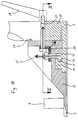
- the saw blade can be pivotable about a pivot axis to change the inclination of the saw blade with respect to the main plane of the table plate in the first and in the second position thereof, said pivot axis running parallel to the longitudinal direction of said through slot, the central axis of the pivot axis preferably lying in the longitudinal centre plane of the through slot.
- the saw blade When the centre axis of the pivot axis is located at half-height between the side of the section of the support element comprising the through slot facing away from the table plate and the second side of the table plate located opposite to said section, the saw blade is displaced not only in the first but also in the second position of the table plate in the same way with regard to the through slot in the support element and the opening in the table plate, so that the width of the through slot and the width of the opening can be minimal.
- the saw blade in the first position of the table plate may be brought into a lowered cutting position, in which it extends into the through slot but lies with its lower periphery above the table plate, to thus achieve a combined chop-cut and pull- or rip-cut function without the cutting width being limited or impaired by the presence of the table plate.
- a lowered cutting position in which it extends into the through slot but lies with its lower periphery above the table plate, to thus achieve a combined chop-cut and pull- or rip-cut function without the cutting width being limited or impaired by the presence of the table plate.
- operating instances can arise when the user may wish to separate workpieces of relatively smaller width and possibly quickly carry out a large number of chop-cuts, without needing the pull- or rip-cut function.
- the saw blade can, in at least its centre position, be lowerable beyond the lowered cutting position, say by correspondingly adjusting the stop arrangement, so that the saw blade can be guided through the through slot and also through at least a portion of the opening in the table plate, i.e. the circular saw arrangement then works as the initially described known circular saw arrangement, as a chop-cut saw.
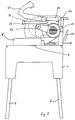
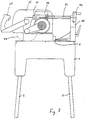
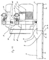
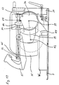
- the circular saw arrangement represented in Figures 1 to 22 has a frame 1 which has four legs 2, and into the top end of which a table plate 3 is inserted rotatable about an axis 5.
- the table plate 3 is defined in its position relative to the frame 1 in the position as per Figures 1 to 5, in which its first side faces upwardly, by means of fixing devices, e.g. the socket pins 4 diagrammatically indicated in Figures 2 and 20, which extend through the frame 1 and into the table plate 3.
- the table plate 3 is essentially rectangular in shape and has recesses at its corners, into which areas of the frame 1 extend, through which pins 4 are guided.
- a fence 6 is mounted to support a workpiece W to be worked, which fence extends at a distance from the rotation axis 5 of the table plate 3 and parallel to the latter.
- the fence 6 has a recess 7 which is limited at one side by an inclined edge 8 ( Figure 1).
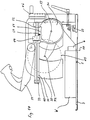
- a support element 15 is mounted rotatable about a rotation axis 14 ( Figures 6 and 11) lying perpendicular to the main plane of the table plate, said support element being in the form of a plate and overlaying areas of the first side of the table plate 3.
- the rotation axis 14 lies in the centre of the recess 7 of the fence 6 and in the plane of the stop face for the workpiece W formed by the fence 6.
- a roughly circular part of the support element 15 is arranged about this rotation axis 14, an elongate section 16 projecting from said circular part.
- a through-passage slot 17 extending in the longitudinal direction of this section is present reaching directly to the rotation axis 14 and is open at its opposite outer end.
- a recess 11 is formed on the first side of the table plate 3, so that the outer edge of the area of the support element 15 facing away from the elongate section 16 of the support element 15 is relatively closely surrounded by the delimitation wall of the recess 11, whilst, at the side of the fence 6 facing the elongate section 16, the recess extends towards the side edges of the table plate 3 which run perpendicular to the rotation axis 5.
- the thus-formed lateral delimitation walls 12 and 13 of the recess 11 terminate at a distance from the edge of the table plate 3 running parallel to the fence 6.
- the side walls 12 and 13 of the recess 11 of the table plate 3 are formed corresponding to the side walls of the elongate section 16 of the support element 15 and form stops, by means of which the rotation of the support element 15 about the rotation axis 14 out of the centre position as per Figure 6 is limited.
- the upper surfaces of the non-recessed parts of the table plate 3 on the left side of the fence 6 in Figures 6 and 8 lie in the same plane as the upper surface of the support element 15 so that the table plate 3 and the support element 15 form supporting sections for a workpiece W, which is laid against the workpiece positioning face of the fence 6 for treatment.
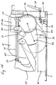
- a slot-like opening 10 is located in the area of the recess 11 of the table plate 3, designed as an insert unit 9 fitted into the table plate 3 and having a longitudinal axis extending through the rotation axis 14 and perpendicular to the workpiece positioning face of the fence 6.
- the slot-like opening 10 is covered by the through-passage slot 17 in the support element 15 or the through-passage slot 17 and the slot-like opening 10 are arranged flush in the centre position.
- the support element 15 is plate-like and has a level lower and a level upper face, the level lower face resting on the level upper face of the table plate 3 in the area of the recess 11.
- the thickness of the support element 15 is chosen to be as small as possible whilst being just strong enough.
- the thickness of the table plate 3 in the area of the slot-like opening 10 should likewise be as small as possible and this thickness preferably equals the thickness of the support element 15 in the section containing the through-passage slot 17. The reason for this will be explained later.
- connection part 22 Secured on the support element 15, say be being welded on, in the area opposite the elongate section 16, at a clearly lesser distance from the rotation axis 14 than the outer end of the through-passage slot 17, is a connection part 22 which on its lower side has a curved duct 23 indicated in Figure 9 with dashes, into which a curved guide rib section 20 forming part of the table plate 3 extends.
- screw bolts 25 Inserted through two bores provided in the connection part 22 and extending from above into the duct 23, are screw bolts 25 which have a lower, angled section 26 extending behind a projecting area 21 of the guide-rib section 20.
- the upper ends of the screw bolts 25 extend through one leg of an angular clamp 24 and are connected to this by means of nuts.
- the other leg of the angular clamp 24 lies adjacent to a perpendicular wall of the connection part 22, and extending through the latter and said wall is a clamping bolt 27 which lies with its head against the surface of the leg of the angular clamp 24 facing away from the perpendicular wall of the connection part 22.
- the clamping bolt 27 extends on the side of the perpendicular wall of the connection part 22 facing away from the angular clamp 24, through a holding part 30 directed perpendicularly upwards. It has a threaded section extending beyond this holding part and engaging by screwing with a clamping lever 28.
- a circular arc-shaped guide groove is formed, indicated in Figure 11 by dashes and with the centre of its circle lying on the rotation axis 56, likewise indicated in Figure 11.
- a guide projection 29, formed at the perpendicular wall of the connection part 22, projects into this guide groove; during sawing with the saw blade aligned perpendicular to the main plane of the table 3, said guide projection lies at the right-hand end, in Figure 11, of the guide groove.
- the clamping lever 28 is once more rotated so that the clamping bolt 27 once more applies a load to the angular clamp 24 supporting itself with the cutting area of the legs in a rise in the connection part 22, the leg of the angular clamp 24 engaging with the clamping bolt 27, perpendicular in Figure 10, is moved in the direction of the perpendicular wall of the connection part 22 and so tilted to the extent of the rise at the connection part 22.
- the other leg of the angular clamp 24 raises the screw bolt 25 in the direction of the arrow by abutment against its nut and clamps the angled section 26 of the screw bolt 25 by abutment against the projecting area 21 of the guide-rib section 20 forming part of the table plate 3. In this way the position of the holding part 30 and support element 15 relative to the first side of the table plate 3 is defined.
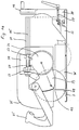
- a guide means is present in the shape of two guide rods 31, 32, running at a distance from, and parallel to, each other, having a circular cross-section and connected at their free end by a transverse element 33.
- the guide rods 31 and 32 run parallel to the main plane of the table plate 3 and thus also parallel to the support surfaces, formed by the first side of the table plate 3 in cooperation with the support element 15, for a workpiece W to be treated.
- the two guide rods 31 and 32 extend, parallel to the longitudinal direction of the through-passage slot 17, in the support element 15 and project over the fence 6 in the direction of the free end on the elongate section 16 of the support element 15.
- a spindle 45 is arranged which has a hexagonal cross-section.
- the spindle 45 is mounted with its outer end rotatable in the transverse element 33 and extends with its inner end through the holding part 30, a hand wheel 46 being mounted on its inner end section projecting from the holding part 30.
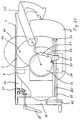
- a slide 34 is arranged, movable in the longitudinal direction of the guide means, on which a holding ring 38 ( Figure 13) is mounted.
- This holding ring coaxially encompasses an electric motor 36 so that the electric motor 36 is rotatable in the holding ring 38 about the longitudinal axis 37 of its armature shaft and thus relative to the slide 34.
- On one end of the armature shaft of the electric motor 36 sits, non-rotatably, a toothed wheel, over which an endless toothed belt 41 is guided.
- the housing section of the electric motor 36 which accommodates the toothed wheel 40, is extended perpendicular to the axis 37 of the armature shaft of the electric motor 36 and accommodates at its outer end a shaft, rotatable about a rotation axis 42, to which shaft the circular saw blade 44 is non-rotatably secured and which shaft supports, non-rotatably, a toothed wheel 43 which engages with the endless toothed belt 41.
- the toothed belt 41 is thus driven by its toothed wheel 40, and thus, via the engagement of the toothed belt 41 with the toothed wheel 43, the saw blade 44 is rotated about the axis 42.
- a protective hood 35 which encloses and protects the upper part of the saw blade 44.
- a hand grip 55 is mounted in the way recognizable in Figures 14 to 17.
- the user can thus move the saw unit containing the electric motor 36 and the saw blade 44 out of the position as per Figure 14 or Figure 3 against the force of a spring, not shown, by moving the hand grip 55 downwards.
- This movement leads to a downward movement of the housing part 39 and thus to a rotational movement of the electric motor 36 about the axis 37 of its armature shaft and also to a downward movement of the saw blade 44 into the position as per Figure 15 or Figure 4.
- the user can carry out pure chop-cuts by performing the previously mentioned lowering of the saw blade 44 by means of pivoting about the axis 37 of the electric motor 36 and thus moving the saw blade 44 through the through-passage slot 17 in the support element 15 and the slot-like opening 10 in the area of the recess 11 of the table plate 3, in order to separate a workpiece, as the saw blade position in Figure 16 shown by dashes indicates.
- the circular saw arrangement represented is not used to carry out pure chop-cuts but a large cut width is to be achieved with it by combining chop-cut saw function with rip-saw function.
- a limiting stop arrangement is present which essentially determines the position of the saw blade 44 during use.
- the limiting stop arrangement contains a stop 50, which is part of a stop element 49 that engages by screwing with the outer thread 48 of an adjusting bush 47 ( Figure 27).
- the adjusting bush 47 is mounted axially non-movable, but rotatable in the slide 34 and sits non-rotatable and axially slidable on the spindle 45 which has a hexagonal cross-section and extends between the guide rods 31 and 32.
- the spindle 45 is rotated about its longitudinal axis by the user by actuation of the hand wheel 46, the screw engagement of adjusting bush 47 rotating of itself together with the spindle 44 and of stop element 49 causes an axial displacement of the stop element 49 along the adjusting bush 47.
- the stop element 49 can be moved for example into the position as per Figures 14 and 16, and in this position, as Figures 14 and 16 show, it can be moved together with the slide 34 along the guide rods 31, 32.
- the limiting stop arrangement has a recess 51 ( Figure 11), which, at its right-hand end in Figures 14 to 16, forms a stop face 52. Further, offset clockwise in the distance from the stop face 52 in Figures 14 to 16, a stop recess 53 is formed whose function will be described later.
- the cutting position is determined by the furthest left position of the stop element 49, i.e. by an end position of the stop element 49.
- the saw blade 44 extends into the through-passage slot 17 in the support element 15, but does not project over or beyond the underside of the support element 15, i.e. the saw blade 44 is always above the plane formed by the upper surface of the recess 11 of the table plate 3. Therefore, the saw blade 44 does not cut into this table plate even if the support element 15 is rotated out of the centre position as per Figure 16 into a mitre position, say as per Figure 8.
- the workpiece W is initially cut into or through by means of a chop-cut by lowering the saw blade 44 from the position as per Figure 14 into the position as per Figure 15, in which the stop face 52 in the housing of the electric motor 36 abuts against the stop 50, so that no further lowering is possible, but the cutting position of the saw blade 44 is reached in which the lowest point of the saw blade 44 lies above the table plate 3.
- the user can move the saw blade 44 into the position as per Figure 16, while maintaining this lowered position, by pulling on the hand grip 55 and through the resultant displacement movement of the slide 34 along the guide rods 31 and 32 in the form of a rip cut, in order thus to completely separate the workpiece W, the lower part of the saw blade 44 always extending into the through-passage slot 17 in the support element 15.
- the saw blade 44 can be brought, by rotation of the support element 15 and of the holding part 30 connected to it about rotation axis 14, into a mitre-cut position in which it is no longer aligned perpendicular to the workpiece positioning face of the fence 6. Operation with a large cut width is also possible in such a mitre-cut position since, although the saw blade 44 extends, in the lowered cutting position as per Figures 15 and 16, into the through-passage slot 17 of the support element 15, it is always above the table plate 3.
- the saw blade 44 can be brought, by rotation of the support element 30 in the manner described above about the axis 56, into an inclined position relative to the main plane of the table plate 3 in order to make corresponding cut paths.
- the edge areas of the recess 7 in the fence 6 do not come into contact with the saw blade, the limiting edge 8 slopes, as shown in Figure 11. Accordingly, the adjacent wall of the through-passage slot 17 is also inclined.
- the axis 56 about which the saw blade 44 is rotated into an inclined position lies at half height between the upper surface of the elongate section 16 of the support element 15 and the second side, i.e. the lower side in Figure 11, of the table plate 3. The reason for this will be explained later.
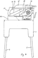
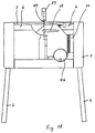
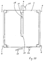
- the table plate 3 is pivotable about the axis 5. If, therefore, the socket pins 4 are withdrawn in the position as per Figures 1 to 5, the table plate 3 can be rotated by 180 degrees, so that the second side of the table plate 3 is directed upwards, while the first side, and thus the support element 15 secured thereto, the guide means connected to the latter and the saw unit with electric motor 36 and saw blade 44 attached to the guide means are on the underside and thus within the frame 1, as shown in Figures 18 and 19. In this position, the socket pins 4 are re-inserted ( Figure 20) in order to fix the table plate relative to the frame 1.
- the support element 15 must be in the centre position as per Figure 6, so that the through-passage slot 17 is flush with the slot-shaped opening 10 present in the table plate 3. If, therefore, the stop element 49 is pivoted, in the manner indicated in the upper representation in Figure 11, from the area of the stop face 52, the user can raise the saw blade 44, by raising the hand grip 55, through the through-passage slot 17 and the slot-shaped opening 10, so that a section of the saw blade 44 projects over the second side, now lying on top, of the table plate 3.
- This raising movement is accompanied by a corresponding pivoting of the electric motor 36 about its axis 37 until the stop recess 53 formed in the housing wall of the motor 36 is in the area of the stop 50. If the stop element 49 is then pivoted back and the stop 50 thus made to engage with the stop recess 53, the stop 50 supports the electric motor 36 and thus the saw blade 44 in a position projecting over the second side of the table plate 3.
- a riving knife 58 and a protective cover 57 Such a riving knife can be inserted for fitting from above through a section of slot-shaped opening 10 and through-passage slot 17 not filled by the saw blade 44 and secured to the protective cover 35 in a manner that is not shown.
- the protective cover 57 can be attached at the upper end of the riving knife 58.
- Fences can also be attached to the second side of the table plate 3 to guide the workpiece to be machined.
- the axis 56 is arranged centrally relative to the total thickness of table plate 3 and support element 15, is advantageous in that the displacement movements of the saw blade 44 relative to through-passage slot 17 and slot-shaped opening 10 are, in the case of movement into an inclined position, the same in the position as per Figures 1 to 17 and in the position as per Figures 18 to 20, i.e. the widths of through-passage slot 17 and of slot-shaped opening 10 can be minimal.
Landscapes
- Engineering & Computer Science (AREA)
- Mechanical Engineering (AREA)
- Life Sciences & Earth Sciences (AREA)
- Wood Science & Technology (AREA)
- Forests & Forestry (AREA)
- Sawing (AREA)
Claims (29)
- Kreissägeanordnung mit einem Rahmen (1), an dem eine Tischplatte (3) gehaltert ist, die zwischen einer ersten Stellung, in der ihre erste Seite nach oben weist, und einer zweiten Stellung verschwenkbar ist, in der ihre zweite Seite nach oben weist, wobei die Tischplatte (3) sowohl in ihrer ersten als auch in ihrer zweiten Stellung unverlagerbar mit dem Rahmen (1) verbindbar ist, ferner mit einem an der Tischhplatte (3) um eine bezüglich der Tischplattenhauptebene senkrechte Drehachse (14) drehbar angeordnetem Trägerelement (15), das zusammen mit der ersten Seite der Tischplatte (3) Werkstückabstützabschnitte bildet, die in der gleichen Ebene liegen, und das eine ein angetriebenes Sägeblatt (44) enthaltende Sägeeinheit trägt, wobei das Sägeblatt (44) sich in der ersten Stellung der Tischplatte (3) aus einer angehobenen Stellung nach unten bewegen läßt, um ein Werkstück (W) zu schneiden, und aus einer Mittelstellung in eine Gehrungsstellung bewegt werden kann und wobei sich die Sägeeinheit in der zweiten Stellung der Tischplatte (3) unterhalb der Tischplatte (3) befindet und das Sägeblatt (44) sich mit einem Abschnitt durch einen Durchtrittsschlitz (17) im Trägerelement (15) und nach oben über die zweite Seite der Tischplatte (3) erstreckt, dadurch gekennzeichnet, daß sich das Trägerelement (15) an der ersten Seite der Tischplatte (3) befindet und sich über einen Teil von dieser erstreckt, daß sich das Sägeblatt (44) in einer Schneidstellung oberhalb des vom Trägerelement (15) überdeckten Teils der Tischplatte (3) befindet und zumindest in dieser Stellung in Richtung der Längserstreckung des Durchtrittsschlitzes (17) bewegbar ist, und daß in der Tischplatte (3) eine Öffnung (10) vorhanden ist, die in der Mittelstellung des Sägeblattes (44) von zumindest einem Teil des Durchtrittsschlitzes (17) überdeckt wird und durch die und den Durchtrittsschlitz (17) sich das Sägeblatt (44) in der zweiten Stellung der Tischplatte (3) erstreckt.
- Kreissägeanordnung nach Anspruch 1, dadurch gekennzeichnet, daß an der ersten Seite der Tischplatte (3) eine Anschlaganordnung (6) vorgesehen ist, die eine Werkstückanlagefläche zum Positionieren des zu schneidenden Werkstücks (W) bildet.
- Kreissägeanordnung nach Anspruch 2, dadurch gekennzeichnet, daß die Anschlaganordnung (6) im sägeblattnahen Bereich eine Aussparung (7) für den Durchtritt eines Teils des Sägeblattes (44) aufweist.
- Kreissägeanordnung nach Anspruch 3, dadurch gekennzeichnet, daß sich die Drehachse (14) des Trägerelementes (15) im Bereich der Aussparung (7) der Anschlaganordnung (6) befindet.
- Kreissägeanordnung nach Anspruch 4, dadurch gekennzeichnet, daß die Drehachse (14) des Trägerelementes (15) in der Ebene der Anlagefläche der Anschlaganordnung (6) liegt.
- Kreissägeanordnung nach einem der Ansprüche 2 bis 4, dadurch gekennzeichnet, daß die Sägeeinheit an der der Werkstückanlagefläche der Anschlaganordnung (6) abgewandten Seite mit dem Trägerelement (15) verbunden ist.
- Kreissägeanordnung nach Anspruch 6, dadurch gekennzeichnet, daß der Befestigungsbereich für die Sägeeinheit am Trägerelement (15) einen geringeren Abstand von der Drehachse (14) des Trägerelementes (15) hat als das äußere Ende des Durchtrittsschlitzes (17).
- Kreissägeanordnung nach einem der Ansprüche 1 bis 7, dadurch gekennzeichnet, daß die Tischplatte (3) an ihrer ersten Seite eine zumindest den den Durchtrittsschlitz (17) des Trägerelementes (15) aufweisenden Abschnitt des Trägerelementes (15) aufnehmende Vertiefung (11) aufweist.
- Kreissägeanordnung nach Anspruch 8, dadurch gekennzeichnet, daß die Tiefe der Vertiefung (11) gleich der Höhe des aufgenommenen Abschnittes des Trägerelementes (15) ist.
- Kreissägeanordnung nach Anspruch 8 oder 9, dadurch gekennzeichnet, daß Seitenwandabschnitte (12, 13) der Vertiefung (11) als Anschläge zur Begrenzung der Verlagerung des Trägerelementes (15) aus der Mittelstellung dienen.
- Kreissägeanordnung nach einem der Ansprüche 1 bis 10, dadurch gekennzeichnet, daß der Durchtrittsschlitz (17) in einem mit seiner Längserstreckung in Richtung des Durchtrittsschlitzes (17) verlaufenden, länglichen Abschnitt (16) des Trägerelementes (15) ausgebildet ist.
- Kreissägeanordnung nach einem der Ansprüche 1 bis 11, dadurch gekennzeichnet, daß das Sägeblatt (44) in der ersten Stellung und in der zweiten Stellung der Tischplatte (3) zur Veränderung seiner Neigung bezüglich der Tischplattenhauptebene um eine Schwenkachse (56) verschwenkbar ist, die parallel zur Längserstreckung des Durchtrittsschlitzes (17) verläuft.
- Kreissägeanordnung nach Anspruch 12, dadurch gekennzeichnet, daß die Schwenkachse (56) in der Längsmittelebene des Durchtrittsschlitzes (17) liegt.
- Kreissägeanordnung nach Anspruch 12 oder 13, dadurch gekennzeichnet, daß die Schwenkachse (56) auf halber Höhe zwischen der der Tischplatte (3) abgewandten Seite des den Durchtrittsschlitz (17) aufweisenden Teils des Trägerelementes (15) und der diesem Teil gegenüberliegenden zweiten Seite der Tischplatte (3) liegt.
- Kreissägeanordnung nach einem der Ansprüche 1 bis 14, dadurch gekennzeichnet, daß das Sägeblatt (44) zumindest in seiner Mittelstellung zur Durchführung von Trennschnitten über die abgesenkte Schneidstellung hinaus absenkbar ist.
- Kreissägeanordnung mit- einem Rahmen (1),- einer am Rahmen (1) befestigten Tischplatte (3), die zwischen einer ersten Stellung, in der ihre erste Seite nach oben weist, und einer zweiten Stellung verschwenkbar ist, in der ihre zweite Seite nach oben weist,- Festlegemitteln (4) zum unverlagerbaren Verbinden der Tischplatte (3) mit dem Rahmen (1) in der ersten und in der zweiten Stellung,- einem Trägerelement (15), das drehbar an der Tischplatte (3) befestigt ist, so daß es zumindest in der ersten Stellung der Tischplatte (3) um eine senkrecht zur Tischplattenhauptebene verlaufene Drehachse (14) gedreht werden kann, und- einer am Trägerelement (15) befestigten Sägeeinheit, die das angetriebene Sägeblatt (44) enthält, wobei sich das Sägeblatt (44) in der ersten Stellung der Tischplatte (3) aus einer Mittelstellung in eine Gehrungsstellung verlagern läßt und zum Durchschneiden eines Werkstücks (W) aus einer angehobenen Stellung in das Werkstück und dann mit seinem unteren Umfangsbereich in den Durchtrittsschlitz (17) des Trägerelementes (15) abgesenkt werden kann, und wobei das Sägeblatt (44) in der zweiten Stellung der Tischplatte (3) in einer Sägestellung gehalten werden kann, in der es sich in seiner Mittelstellung befindet und mit einem Abschnitt durch einen Durchtrittsschlitz (17) im Trägerelement (15) hindurch über die zweite Seite der Tischplatte (3) nach oben vorsteht,
dadurch gekennzeichnet,- daß das Trägerelement (15) an der ersten Seite der Tischplatte (3) vorgesehen ist und sich über einen Teil dieser ersten Seite erstreckt,- daß eine Begrenzungsanschlageinrichtung (49, 50, 51, 52) vorgesehen ist, die die Absenkbewegung des Sägeblattes (44) aus der angehobenen Stellung in eine abgesenkte Schneidstellung begrenzt, in der sich das Sägeblatt (44) in den Durchtrittsschlitz (17) erstreckt und sich der untere Punkt des Umfangs des Sägeblattes (44) oberhalb des vom Trägerelement (15) überdeckten Bereichs der Tischplatte (3) befindet,- daß das Sägeblatt (44) zumindest in einer abgesenkten Stellung in Längsrichtung des Durchtrittsschlitzes (17) bewegbar ist und- daß in der Tischplatte (3) eine Öffnung (10) vorhanden ist, die in der Mittelstellung des Sägeblattes (44) von zumindest einem Teil des Durchtrittsschlitzes (17) des Trägerelementes (15) überdeckt wird, wobei sich in der zweiten Stellung der Tischplatte (3) das in der Sägestellung befindliche Sägeblatt (44) durch den Durchtrittsschlitz (17) im Trägerelement (15) und durch die Öffnung (10) in der Tischplatte (3) erstreckt. - Kreissägeanordnung nach Anspruch 16, dadurch gekennzeichnet, daß der Abstand des Befestigungsbereichs für die Sägeeinheit am Trägerelement (15) von der Drehachse (14) des Trägerelementes (15) geringer ist als der Abstand des äußeren Endes des Durchtrittschlitzes (17) von dieser.
- Kreissägeanordnung nach Anspruch 16 oder 17, dadurch gekennzeichnet, daß auf der ersten Seite der Tischplatte (3) eine Vertiefung (11) zur Aufnahme des den Druchtrittsschlitz (17) aufweisenden Abschnitts des Trägerelementes (15) vorgesehen ist.
- Kreissägeanordnung nach Anspruch 18, dadurch gekennzeichnet, daß die Tiefe der Vertiefung (11) gleich der Höhe des von ihr aufgenommenen Teils des Trägerelementes (15) ist.
- Kreissägeanordnung nach Anspruch 18 oder 19, dadurch gekennzeichnet, daß die Vertiefung (11) Seitenwandabschnitte (12, 13) aufweist, die Anschläge für das Trägerelement (15) bilden, durch die der Bereich der Gehrungsstellungen für das Sägeblatt (44) begrenzt wird.
- Kreissägeanordung nach einem der Ansprüche 18 bis 20, dadurch gekennzeichnet, daß die Materialdicke der Tischplatte (3) im Bereich der Vertiefung (11) zumindest in etwa gleich der Höhe des den Durchtrittsschlitz (17) enthaltenden Teils des Trägerelementes (15) ist.
- Kreissägeanordnung nach Anspruch 21, dadurch gekennzeichnet, daß die Halterung (22, 30) zur Befestigung der Sägeeinheit am Trägerelement (15) unterteilt ist, so daß das Sägeblatt (44) sowohl bei in der ersten Stellung befindlicher Tischplatte (3) als auch bei in der zweiten Stellung der Tischplatte (3) in der Sägestellung befindlichem Sägeblatt (44) um eine Schwenkachse (56), die parallel zur Längserstreckung des Durchtrittsschlitzes (17) verläuft, in eine geneigte Stellung bezüglich der Hauptebene der Tischplatte (3) verlagert werden kann.
- Kreissägeanordnung nach Anspruch 22, dadurch gekennzeichnet, daß die Schwenkachse (56) auf halber Höhe des Abstandes von der der Tischplatte (3) abgewandten Seite des den Durchtrittsschlitz (17) enthaltenden Teils des Trägerelementes (15) und der diesem Teil gegenüberliegenden zweiten Seite der Tischplatte (3) liegt.
- Kreissägeanordnung nach Anspruch 22 oder 23, dadurch gekennzeichnet, daß die Schwenkachse (56) in der Längsmittelebene des Durchtrittsschlitzes (17) liegt.
- Kreissägeanordnung nach einem der Ansprüche 16 bis 24, dadurch gekennzeichnet, daß das Trägerelement (15) einen länglichen Abschnitt (16) aufweist, dessen Längserstreckung in Richtung der Längserstreckung des Durchtrittschlitzes (17) verläuft und das zumindest den äußeren Teil des Durchtrittschlitzes (17) aufweist.
- Kreissägeanordnung nach Anspruch 25, dadurch gekennzeichnet, daß der längliche Abschnitt (16) des Trägerelementes (15) von einem runden Abschnitt ausgeht, in dessen Mitte sich die Drehachse (14) befindet.
- Kreissägeanordnung nach einem der Ansprüche 16 bis 26, gekennzeichnet durch eine Anschlaganordnung (6), die an der ersten Seite der Tischplatte (3) befestigt ist und sich zwischen dem Bereich der Befestigung der Sägeeinheit am Trägerelement (15) und dem von dieser Befestigung am weitesten entfernten, äußeren Ende des Durchtrittsschlitzes (17) im Trägerelement (15) befindet, wobei sich in der Mittelstellung des Sägeblatts (44) eine von der Anschlaganordnung (6) gebildete Anlagefläche parallel zur Drehachse (42) des Sägeblattes (44) erstreckt und im sägeblattnahen Bereich eine Aussparung (7) aufweist.
- Kreissägeanordnung nach einem der Ansprüche 16 bis 27, dadurch gekennzeichnet, daß die Begrenzungsanschlagseinrichtung (49, 50, 51, 52) einen in Richtung der Bewegung des Sägeblattes (44) in Längsrichtung des Durchtrittsschlitzes (17) verstellbaren Anschlag (50) aufweist, der mit einer beim Absenken des Sägeblattes (44) eine entsprechende Verlagerungsbewegung ausführenden Anschlagfläche (52) zusammenwirkt, die die Absenkbewegung des Sägeblattes (44) durch Eingriff mit dem Anschlag (50) begrenzt.
- Kreissägeanordnung nach Anspruch 28, dadurch gekennzeichnet, daß der Anschlag (50) bei in der zweiten Stellung befindlicher Tischplatte (3) das Sägeblatt (44) durch Eingriff mit einer Anschlagvertiefung (53) in seiner Sägestellung hält.
Applications Claiming Priority (2)
| Application Number | Priority Date | Filing Date | Title |
|---|---|---|---|
| DE4106635A DE4106635C1 (de) | 1991-02-28 | 1991-02-28 | |
| DE4106635 | 1991-02-28 |
Publications (2)
| Publication Number | Publication Date |
|---|---|
| EP0502350A1 EP0502350A1 (de) | 1992-09-09 |
| EP0502350B1 true EP0502350B1 (de) | 1997-06-11 |
Family
ID=6426289
Family Applications (1)
| Application Number | Title | Priority Date | Filing Date |
|---|---|---|---|
| EP92102548A Expired - Lifetime EP0502350B1 (de) | 1991-02-28 | 1992-02-15 | Kreissäge-Einrichtung |
Country Status (6)
| Country | Link |
|---|---|
| US (1) | US5189937A (de) |
| EP (1) | EP0502350B1 (de) |
| JP (1) | JP3566313B2 (de) |
| AU (1) | AU640307B2 (de) |
| CA (1) | CA2061590A1 (de) |
| DE (1) | DE4106635C1 (de) |
Families Citing this family (27)
| Publication number | Priority date | Publication date | Assignee | Title |
|---|---|---|---|---|
| DE4345175A1 (de) * | 1993-04-08 | 1994-12-15 | Otto Bergler | Kapp- Gehrungs- und Tischsäge |
| WO1994023878A1 (de) * | 1993-04-08 | 1994-10-27 | Black & Decker Gmbh | Kreissägeanordnung |
| US5425294A (en) * | 1993-06-03 | 1995-06-20 | Hitachi Koki Haramachi Co., Ltd. | Desk-top cutting machine with tiltable saw |
| GB9314165D0 (en) * | 1993-07-08 | 1993-08-18 | Black & Decker Inc | Chop/table saw with parallelogram arrangement |
| GB9314163D0 (en) * | 1993-07-08 | 1993-08-18 | Black & Decker Inc | Chop/table saw arrangement |
| DE4323640A1 (de) * | 1993-07-15 | 1995-01-19 | Otto Bergler | Tisch- und Gehrungssäge mit kombiniertem Tauch- und Radialsägeaggregat |
| US5595124A (en) * | 1994-06-08 | 1997-01-21 | Delta International Machinery Corp. | Restraining mechanism |
| WO1996000638A1 (en) * | 1994-06-29 | 1996-01-11 | Trevor Tisdall | Saw bench |
| GB9526368D0 (en) | 1995-12-22 | 1996-02-21 | Black & Decker Inc | A chop/table saw arrangement |
| GB9526374D0 (en) | 1995-12-22 | 1996-02-21 | Black & Decker Inc | A chop/slide saw |
| DE29603774U1 (de) * | 1996-03-01 | 1997-07-03 | Wolfcraft GmbH, 56746 Kempenich | Vorrichtung zur Aufnahme eines motorgetriebenen Werkzeuges |
| US5778747A (en) * | 1996-11-21 | 1998-07-14 | Rexon Industrial Corp., Ltd. | Power saw having an ergonomically-designed handle and safety switch |
| JP2005279933A (ja) * | 2004-03-26 | 2005-10-13 | Hitachi Koki Co Ltd | 卓上切断機 |
| US7802505B2 (en) * | 2004-04-15 | 2010-09-28 | Milwaukee Electric Tool Corporation | Dust collection assembly for a power tool |
| DE602005007119D1 (de) * | 2004-07-07 | 2008-07-10 | Black & Decker Inc | Tischverriegelungsvorrichtung für Sägen |
| DK1614493T3 (da) * | 2004-07-08 | 2008-02-25 | Black & Decker Inc | Geringssav med et roterbart bord |
| JP2006044070A (ja) * | 2004-08-04 | 2006-02-16 | Makita Corp | フリップオーバーソー |
| JP4650296B2 (ja) * | 2006-02-22 | 2011-03-16 | 日立工機株式会社 | 卓上切断機 |
| GB0606846D0 (en) * | 2006-04-05 | 2006-05-17 | Black & Decker Inc | A Flip Over Saw |
| US7752951B2 (en) * | 2006-09-18 | 2010-07-13 | Normand Ouellette | Convertible circular saw apparatus usable as either a miter saw or a table saw |
| CN101244470B (zh) * | 2007-02-12 | 2010-04-07 | 王骥 | 便于搬运的复合锯 |
| US20080236347A1 (en) * | 2007-03-26 | 2008-10-02 | Kenneth Jack Spencer | Swinging circular saw with lateral movement |
| CN101722332B (zh) * | 2008-10-24 | 2012-03-28 | 苏州宝时得电动工具有限公司 | 斜断锯 |
| JP5666094B2 (ja) * | 2009-01-30 | 2015-02-12 | 株式会社マキタ | 卓上切断機 |
| US9403224B1 (en) * | 2011-06-30 | 2016-08-02 | Carlos Silva | Combined chop saw and work table and associated use thereof |
| US8539870B2 (en) | 2011-10-15 | 2013-09-24 | RBWL Licensing Holdings, LLC | Multifunctional saw apparatus and method |
| US10549364B2 (en) * | 2018-02-19 | 2020-02-04 | Robert Bosch Tool Corporation | Table saw having a dual power train assembly |
Family Cites Families (8)
| Publication number | Priority date | Publication date | Assignee | Title |
|---|---|---|---|---|
| US2851068A (en) * | 1957-06-05 | 1958-09-09 | Goodlet Gilbert | Combination swing and table saw with invertible table |
| US3465793A (en) * | 1966-08-17 | 1969-09-09 | Peter Zuk | Convertible saw |
| US3570564A (en) * | 1968-01-03 | 1971-03-16 | Lutz Kg Maschf Eugen | Convertible circular bench saw and mitering saw |
| US4152961A (en) * | 1978-01-18 | 1979-05-08 | The Singer Company | Radial saw |
| DE3106098A1 (de) * | 1981-02-19 | 1982-09-02 | Eugen Lutz GmbH u. Co Maschinenfabrik, 7130 Mühlacker | Kombinierte tisch- und gehrungssaege |
| US4465114A (en) * | 1982-08-27 | 1984-08-14 | Schumacher Robert C | Woodworking bench |
| DE3347920C2 (de) * | 1983-08-16 | 1986-10-23 | Eugen Lutz GmbH u. Co Maschinenfabrik, 7130 Mühlacker | Sägeeinrichtung |
| DE3329496C2 (de) * | 1983-08-16 | 1986-02-06 | Eugen Lutz GmbH u. Co Maschinenfabrik, 7130 Mühlacker | Sägeeinrichtung |
-
1991
- 1991-02-28 DE DE4106635A patent/DE4106635C1/de not_active Expired - Lifetime
-
1992
- 1992-02-15 EP EP92102548A patent/EP0502350B1/de not_active Expired - Lifetime
- 1992-02-20 CA CA002061590A patent/CA2061590A1/en not_active Abandoned
- 1992-02-24 US US07/840,791 patent/US5189937A/en not_active Expired - Lifetime
- 1992-02-27 AU AU11250/92A patent/AU640307B2/en not_active Ceased
- 1992-02-28 JP JP04313592A patent/JP3566313B2/ja not_active Expired - Fee Related
Also Published As
| Publication number | Publication date |
|---|---|
| DE4106635C1 (de) | 1992-07-23 |
| US5189937A (en) | 1993-03-02 |
| AU640307B2 (en) | 1993-08-19 |
| EP0502350A1 (de) | 1992-09-09 |
| AU1125092A (en) | 1992-09-03 |
| JPH05185318A (ja) | 1993-07-27 |
| CA2061590A1 (en) | 1992-08-29 |
| JP3566313B2 (ja) | 2004-09-15 |
Similar Documents
| Publication | Publication Date | Title |
|---|---|---|
| EP0502350B1 (de) | Kreissäge-Einrichtung | |
| US5239906A (en) | Circular saw arrangement | |
| EP0830912B1 (de) | Tischsäge | |
| CA2713686C (en) | Power tool cutting apparatus | |
| US5040444A (en) | Saw blade position setting apparatus | |
| US6418830B1 (en) | Adjustable fence for a compound miter saw | |
| US5297463A (en) | Adjustable fence for compound miter saw | |
| US5317944A (en) | Adjustable protecting guard apparatus for a blade of a table saw | |
| US5239756A (en) | Hand circular saw, particularly plunge saw | |
| JP3110454B2 (ja) | 木工フライス盤用保護およびガイド装置 | |
| US4614140A (en) | Safety device for rocking arm saw | |
| US20070039441A1 (en) | Multi-function power saw | |
| EP2259889B1 (de) | Kappsägemaschine mit verbesserter schutzvorrichtung | |
| GB2273078A (en) | Adjustable riving knife | |
| EP0949048B1 (de) | Gehrungssäge mit winkeleinstellbarem Anschlag | |
| EP2017046B1 (de) | Tragbare Hobelmaschine | |
| US5345984A (en) | Pin router apparatus | |
| EP0622145A1 (de) | Eine tragbare Kreissäge vom Gleitverbund-Typ | |
| EP1116539B1 (de) | Quersäge | |
| US4679605A (en) | Fence machining device | |
| JPH09300306A (ja) | 削り加工機 | |
| WO1994023877A1 (de) | Kapp-, gehrungs- und tischsäge |
Legal Events
| Date | Code | Title | Description |
|---|---|---|---|
| PUAI | Public reference made under article 153(3) epc to a published international application that has entered the european phase |
Free format text: ORIGINAL CODE: 0009012 |
|
| AK | Designated contracting states |
Kind code of ref document: A1 Designated state(s): CH DE ES FR GB IT LI NL SE |
|
| 17P | Request for examination filed |
Effective date: 19930304 |
|
| 17Q | First examination report despatched |
Effective date: 19940506 |
|
| GRAG | Despatch of communication of intention to grant |
Free format text: ORIGINAL CODE: EPIDOS AGRA |
|
| GRAH | Despatch of communication of intention to grant a patent |
Free format text: ORIGINAL CODE: EPIDOS IGRA |
|
| RBV | Designated contracting states (corrected) |
Designated state(s): CH ES FR GB IT LI NL SE |
|
| GRAH | Despatch of communication of intention to grant a patent |
Free format text: ORIGINAL CODE: EPIDOS IGRA |
|
| REG | Reference to a national code |
Ref country code: DE Ref legal event code: 8566 |
|
| GRAA | (expected) grant |
Free format text: ORIGINAL CODE: 0009210 |
|
| AK | Designated contracting states |
Kind code of ref document: B1 Designated state(s): CH ES FR GB IT LI NL SE |
|
| PG25 | Lapsed in a contracting state [announced via postgrant information from national office to epo] |
Ref country code: CH Effective date: 19970611 Ref country code: LI Effective date: 19970611 Ref country code: NL Free format text: LAPSE BECAUSE OF FAILURE TO SUBMIT A TRANSLATION OF THE DESCRIPTION OR TO PAY THE FEE WITHIN THE PRESCRIBED TIME-LIMIT Effective date: 19970611 Ref country code: ES Free format text: THE PATENT HAS BEEN ANNULLED BY A DECISION OF A NATIONAL AUTHORITY Effective date: 19970611 |
|
| REG | Reference to a national code |
Ref country code: CH Ref legal event code: EP |
|
| ET | Fr: translation filed | ||
| PG25 | Lapsed in a contracting state [announced via postgrant information from national office to epo] |
Ref country code: SE Effective date: 19970911 |
|
| NLV1 | Nl: lapsed or annulled due to failure to fulfill the requirements of art. 29p and 29m of the patents act | ||
| REG | Reference to a national code |
Ref country code: CH Ref legal event code: PL |
|
| PLBE | No opposition filed within time limit |
Free format text: ORIGINAL CODE: 0009261 |
|
| STAA | Information on the status of an ep patent application or granted ep patent |
Free format text: STATUS: NO OPPOSITION FILED WITHIN TIME LIMIT |
|
| 26N | No opposition filed | ||
| REG | Reference to a national code |
Ref country code: GB Ref legal event code: IF02 |
|
| PGFP | Annual fee paid to national office [announced via postgrant information from national office to epo] |
Ref country code: GB Payment date: 20080227 Year of fee payment: 17 Ref country code: IT Payment date: 20080228 Year of fee payment: 17 |
|
| PGFP | Annual fee paid to national office [announced via postgrant information from national office to epo] |
Ref country code: FR Payment date: 20080218 Year of fee payment: 17 |
|
| GBPC | Gb: european patent ceased through non-payment of renewal fee |
Effective date: 20090215 |
|
| REG | Reference to a national code |
Ref country code: FR Ref legal event code: ST Effective date: 20091030 |
|
| PG25 | Lapsed in a contracting state [announced via postgrant information from national office to epo] |
Ref country code: GB Free format text: LAPSE BECAUSE OF NON-PAYMENT OF DUE FEES Effective date: 20090215 Ref country code: FR Free format text: LAPSE BECAUSE OF NON-PAYMENT OF DUE FEES Effective date: 20090302 |
|
| PG25 | Lapsed in a contracting state [announced via postgrant information from national office to epo] |
Ref country code: IT Free format text: LAPSE BECAUSE OF NON-PAYMENT OF DUE FEES Effective date: 20090215 |