EP0502149B1 - Construction et procede correspondant de production - Google Patents
Construction et procede correspondant de production Download PDFInfo
- Publication number
- EP0502149B1 EP0502149B1 EP91915950A EP91915950A EP0502149B1 EP 0502149 B1 EP0502149 B1 EP 0502149B1 EP 91915950 A EP91915950 A EP 91915950A EP 91915950 A EP91915950 A EP 91915950A EP 0502149 B1 EP0502149 B1 EP 0502149B1
- Authority
- EP
- European Patent Office
- Prior art keywords
- fore
- anchoring
- elements
- structure according
- flat material
- Prior art date
- Legal status (The legal status is an assumption and is not a legal conclusion. Google has not performed a legal analysis and makes no representation as to the accuracy of the status listed.)
- Expired - Lifetime
Links
Images


Classifications
-
- E—FIXED CONSTRUCTIONS
- E02—HYDRAULIC ENGINEERING; FOUNDATIONS; SOIL SHIFTING
- E02D—FOUNDATIONS; EXCAVATIONS; EMBANKMENTS; UNDERGROUND OR UNDERWATER STRUCTURES
- E02D29/00—Independent underground or underwater structures; Retaining walls
- E02D29/02—Retaining or protecting walls
- E02D29/0225—Retaining or protecting walls comprising retention means in the backfill
- E02D29/0241—Retaining or protecting walls comprising retention means in the backfill the retention means being reinforced earth elements
Definitions
- the invention relates to a structure according to the Claims 1 and 11.
- the invention further relates to an associated Production method.
- connection is known to be by means of flexible flat material webs achieved in such a way that this with the And anchors connected to the stem or its components then extend into the bulk fill where they are in turn anchored by static friction and / or gearing.
- this is supposed to be a passage of the flat material webs through recesses in the components and thus a complex Operation can be avoided.
- a simple and Construction of the components and anchors which can be produced cost-effectively sought
- EP-A is also a tie anchor with a band-shaped Flat material and with cone-like, protruding upwards Abutment elements on the concrete parts of the stem are known.
- There loops formed at the ends of the tape must go vertically over the Abutment pins are slipped, which is a twist of the Drawstrings in their horizontal cross-sectional position inside the Bulk filling conditionally, as it already is because of the necessary Vertical compaction of the bulk material is unavoidable. Thereby there is an uneven tension distribution in the strip cross-section with reduced strength.
- a first object of the invention is to create a structure in which the aforementioned disadvantages are overcome are.
- the task also extends to a procedure with which the bulk material filling behind chessboard-like Stems as they are preferred for structures of the present type applied, quickly and trouble-free, i.e. especially without Pressing out the bulk material through the gaps in the checkerboard arrangement, can be compressed.
- a further one The object of the invention is to create a structure that with respect Stability and internal bond strength, especially the bond strength between the stem and the one behind it Filling material, technical progress achieved.
- a modification of this invention task to a Reduction of manufacturing costs directed both Component costs as well as the construction costs of the building.
- the invention is also applicable to a manufacturing process directed
- the task solution according to the invention is in two variants determined by the features of claims 1 and 11.
- These Solution variants are based on a common inventive idea connected, namely an increase in internal bond strength between stem and mass structure avoiding a substantial risk of damage to the flat material web by pressing between colliding concrete parts.
- this idea is with the help of up or realized below free abutments, on the the flexible flat material without pressing between concrete parts into the bulk material filling the training according to claim 5 can be a significant protection of the flat material by means of anchoring connection elements can be achieved, at most in small areas of the Web width of the flat material over this on abutment elements act.
- the solution according to claim 11 enables extensive The flat material is kept free of lateral forces by the Concrete parts with the help of intermediate support elements.
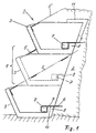
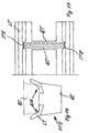
- a first embodiment of the invention is based on the in Fig.1 shown schematically in a vertical cross-section Building explained.
- the building a space lattice construction Slope construction, consists of a stem 1 and a fill material 2, which is arranged essentially behind the stem
- the stem includes a variety of frame or trough-like components 3, which overlook the front of the Building in chessboard-like distribution next to and on top of each other are arranged. This results in the Wall front between the building elements also like a chessboard distributed gaps 4.
- the bulk material extends into the Cavities of the components 3 and in the gaps 4 of the wall front, around here a multitude of regularly distributed embankments 5 form.
- the porch shows for a variety of Components each have at least one of a flat material web 6 wholly or partially entwined and with the stem 1 in Power transmission connection standing solid armature 7.
- the Flat material webs extend from the porch into the Bulk material filling and are in this by weight pressing and compression anchored positively or non-positively. Thereby forms the stem, which is not stable or even stable with the filling material, which is also not stable on its own a stable unit.
- the anchors reach behind in the area of the rear of the stem formed, essentially transversely to the direction of tension of the flat material web freely projecting abutment 8 there is a positive connection between anchor and Component.
- the flat material webs then extend to the loop of the anchor with at least partially adjacent Roundtrip 9 and 10 over the abutment away to fill the bulk material. If necessary, also comes Version with abutment protruding from top to bottom in Consideration.
- the flat material webs run between Anchors and abutments, so that there is a desired tension the lanes results. Basically, there is only one partial wrap around the anchor or missing or only partial path guidance between anchor and abutment into consideration. With the advantage of simple shape and manufacturability the abutments in the example on the back of the components arranged and as strip-shaped approaches with free upwards protruding longitudinal edge.
- the bulk material filling is used in the construction of the building on the back of the stem according to the layers
- the stem is inserted and compacted in layers.
- the gaps between the horizontal neighboring components of a layer by at least one each Support bracket 11 is bridged, at least at its end portions has an angular profile and with this Profile in the horizontal and vertical directions on each supports adjacent components and in turn that in the bulk material in question against displacement supports to the front of the building.
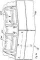
- FIG reproduced perspective representation It is a matter of a space lattice structure, namely an embankment retaining wall, with a stem VB, which as a space lattice made of solid support elements FTE is built, and with a mass structure MT, the pourable or solidified filling material contains FMA and with the Stem is in positive and / or non-positive connection. It can possibly with advantage several stems and several mass structures through a suitable positive or non-positive connection be united in an overall structure.
- At least part of the support elements FTE are intermediate support elements ZTF or ZTS are provided, which are preferably horizontal and extend along the wall level E-E and with neighboring ones Sections of space lattice support elements are connected.
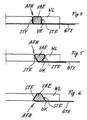
- intermediate support elements in the embodiments according to FIGS. 2 and 3 ZTF, which with positive locking connections FR adjacent sections of the same space lattice support element are connected.
- Intermediate support elements ZTS cohesively, in particular in one piece, with adjacent sections of the same space lattice support element connected.
- Such intermediate load-bearing elements can be subjected to stresses and soil conditions with a front area and / or a rear area Area of a space lattice support element or two Adjacent space grid support elements.
- Corresponding is also in the figures mentioned for below or area of a space lattice support element indicated.
- a rearward arrangement of the intermediate support element enables preferably an additional support or anchoring function between the relevant main support element and the filling material of the mass structure by embedding an intermediate support element or several of them in the pourable or solidifiable Filling material.
- An arrangement in the front and above all this is also the case in the upper area of the main support element preferred for an additional holder of plantable Fill material in the stem into consideration.
- An arrangement in the bottom and especially in the rear area of the main support element offers advantages regarding an additional anchoring function by means of flexible anchoring elements, in particular in the form of GTX geotextile, which on the one hand Loop around or between several support elements on the other hand with the filling material of the mass structure and / or are non-positively connected.
- Figures 4 to 6 show special versions of a force and even positive connection of the stem or its Support elements with the filling material of the mass structure by flexible, preferably flat tension anchoring element GTX or more of the same.
- This is for at least one Space lattice support element at least one at least partially elongated, essentially transverse to the anchoring pull direction extending from at least one such anchoring element, preferably a geotextile, at least partially wrapped anchor connection element VAE intended.
- the space lattice support element itself in operative connection with the anchoring connection element Abutment WL with at least one, preferably at an angle Support surface STF extending transversely to the anchoring tensile direction and with at least one protruding downward, too at an angle, preferably transverse to the anchoring pull direction extending deflection edge UK for the flexible anchoring element intended.
- the flexible anchoring element extends below this deflection edge into the filling material of the Mass structure. Such an arrangement favors you straight course of the anchoring element in the filling material beyond the deflection edge and thereby enables a tight Anchoring.
- the emergence of the Anchorage connection element prevents tilting moments.
- the abutment is for the here e.g. rod-shaped anchoring connection element designed so that at least one of the anchoring connection element Sectionally adapted shape, in particular groove or slit-shaped recording AFN with at least two each other oppositely arranged, also at least partially at an angle, preferably across the anchoring pull direction extending support surfaces STF for the anchoring connection element results.
- 5 and 6 is the bar and Receiving cross-section trapezoidal or wedge-shaped, whereby the possibility of a secure position in a simple way Jamming of the connection element on the support element results.
- this working method provides for a shift by shift Construction of the front space grille and the mass structure essential advantage that only one leveling for each shift must be made and all work essentially play on one level.
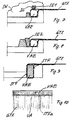
- FIG. 7 a rod or peg-shaped securing element SE1 in one form-fitting opening DS in the side walls SW of the Space lattice support element used.
- This security element supports the beam-shaped anchoring connection element from above and thus prevents the latter from being lifted under the Effect of the tensile forces of the geotextile. The same will happen with the Version according to Fig.
- the space lattice support element at least one with interruptions or paragraphs UA Support surface STFa on only a predetermined number of Sections, preferably only at both end sections of the Anchoring connection element attacks and otherwise with Distance runs from the anchoring connection element. So results there is a perfect separation of functions between the geotextile connection on the one hand and the positive connection between Connection element and support element on the other hand.
- 11 to 13 is also for the positive connection of train anchoring elements with Space lattice support elements, preferably a beam-like anchoring connection element provided, however in connection with various positive locking devices for securing the position of the Connecting element.
- 11 is the position securing device as screw connection LVS with on the connection element attacking angle bracket formed, as shown in Fig.12 as simple flat beam LVB, which lies on the connection element and due to its own weight and the load from the filling material a weight protection against lifting and tipping the Connection element forms.
- FIG. 13 is similar to that of Figure 7, but here is one over the entire width of the box-like space lattice support element extending and through openings OE in both side walls inserted bar intended as a security element, the one slot or groove-shaped receptacle with two support surfaces can be dispensed with makes.
- Fig. 14 again shows a space lattice structure with stem VB, the is designed as a space lattice with solid support elements, and with a mass structure MT, the pourable or solidified FMA contains filler material and with the stem in shape and / or There is a non-positive connection, the stem being a plurality of arranged in a grid pattern in width and height, has chewing or frame-like supporting elements FTE.
- the peculiarity here is that in the area of a Vertical edge FK which runs parallel or at an acute angle Front surface of the space lattice structure at least part of the this edge adjacent support elements at least in the installed state approximately mutually parallel side boundary edges SBK having. This gives the filler some protection against washing out and a satisfactory aesthetic effect of the Facade.
- Fig. 15 shows a concrete structure with extensive, side and stacked front elements.
- the front surface of the Are at least approximately in the direction of the fall, an overlying, parallel or acute angle to Horizontal deepening or subsequent joint VT Water drainage channel was formed.
- the gutters have a wider, upper and a narrower, lower section as well as a transition section arranged in between with a partially pyramidal or partially conical surface.
- Such Facade design avoids an irregular spread of running rainwater with annoying contamination of the Visible surface and also allows an aesthetically satisfactory Facade structure.
- Figures 16 and 17 show a partial section of a Space lattice structure with box-like or frame-like supporting elements FTE that have at least one longitudinal member LT and at least one the latter molded or attached cross member QT and / or Have bottom section BA.
- FTE box-like or frame-like supporting elements
- LT longitudinal member
- QT cross member
- / or Have bottom section BA In the area between the side members and Cross members or bottom section are recesses open at the top ASN for the engagement of support elements STE of an adjacent one Component formed. This enables a simple form-fitting position securing of the one above the other Support elements against each other.
- Fig. 18 shows two adjacent components for a space lattice structure, with at least one front element FW and at least two mutually spaced side elements SW. If necessary, at least one rear element be provided.
- the front element is included provide at least one lateral boundary, preferably with two opposite side boundaries, where at least one page boundary in the floor plan above each adjacent side element protrudes freely.
- the maximum height of the Front element is less than the maximum side element height dimensioned. It is also important that the Floor element with at least one lateral boundary, preferably with two opposite side boundaries, in the floor plan over the adjacent side element protrudes freely.
- Fig. 19 and 20 show box-like components in a grid-like Assembly within a space lattice structure. Every component is with a front wall upright in cross section and also upright transverse or side walls and with provided a rear wall and a floor element. Is essential here u.a. a front wall from with respect to the transverse or side wall lower maximum height and - in the embodiment according to Fig. 19 - a rearward sloping front edge of the transverse or side wall.
- This design enables a comparatively large access opening for the plantable filling of the stem without impairment the support between the superimposed components, i.e. without reducing the bond strength of the stem.
- front sections FAB at least a part of the adjacent support elements FTE by the colliding profile contours form-fitting bridging elements KLE are connected. With that a Wash-out of the filling material can be prevented safely.
Landscapes
- Engineering & Computer Science (AREA)
- Structural Engineering (AREA)
- General Life Sciences & Earth Sciences (AREA)
- Mining & Mineral Resources (AREA)
- Paleontology (AREA)
- Civil Engineering (AREA)
- General Engineering & Computer Science (AREA)
- Environmental & Geological Engineering (AREA)
- Life Sciences & Earth Sciences (AREA)
- Retaining Walls (AREA)
- Pit Excavations, Shoring, Fill Or Stabilisation Of Slopes (AREA)
- Bridges Or Land Bridges (AREA)
- Moulding By Coating Moulds (AREA)
- Diaphragms For Electromechanical Transducers (AREA)
- Sewage (AREA)
- Conveying And Assembling Of Building Elements In Situ (AREA)
- Piles And Underground Anchors (AREA)
- Forging (AREA)
- Joining Of Building Structures In Genera (AREA)
Claims (25)
- Construction, notamment mur, caractérisée par la combinaison des caractéristiques suivantes:a) il est prévu au moins un avant-corps (1) réalisé partiellement d'une manière rigide, constitué d'éléments de support (3) disposés les uns au-dessus des autres, et au voisinage du côté arrière de celui-ci un remplissage de matières en vrac (2);b) l'avant-corps et le remplissage de matières en vrac sont en liaison de traction par concordance des formes ou par force par au moins une bande de matériau plat molle et flexible (6), de préférence une pluralité de telles bandes;c) l'avant-corps présente au moins un ancre de corps solide (7) entouré par une bande de matériau plat au moins partiellement et en liaison de transmission de force avec l'avant-corps, s 'étendant sensiblement parallèlement au plan de mur;d) la bande de matériau plat s'étend depuis l'avant-corps dans le remplissage de matières en vrac et est ancrée dans celui-ci par concordance des formes ou par force;e) l'ancre de corps solide passe derrière au moins une butée (8) formée au voisinage du côté arrière d'un élément de support (3) de l'avant-corps, qui est réalisée sensiblement transversalement à la direction de traction de la bande de matériau plat, en faisant saillie librement vers le haut ou vers le bas;f) la bande de matériau plat est guidée sans compression entre les faces dures d'éléments de support disposés les uns au-dessus des autres, avec une déviation par la butée dans le remplissage de matières en vrac au côté arrière de l'avant-corps.
- Construction selon la revendication 1, caractérisée en ce que la bande de matériau plat (6), à la suite de l'enroulement de l'ancre, s'étend avec les brins aller et retour, au moins partiellement en application, au-delà de la butée (8) au remplissage de matières en vrac (2).
- Construction selon la revendication 1 ou 2, caractérisée en ce que la bande de matériau plat (6) est disposée au moins partiellement entre l'ancre (7) et la butée (8).
- Construction selon l'une des revendications précédentes, caractérisée en ce que l'avant-corps (1), d'une manière connue, est réalisé comme grille spatiale constituée d'éléments de construction (3) disposés les uns au-dessus des autres et/ou les uns à côté des autres de préférence on forme d'auge, et en ce qu'il est prévu au moins une butée (8) qui est disposée au côté arrière d'un élément de construction et constitue une arête longitudinale faisant saillie librement vers le haut.
- Construction selon l'une des revendications précédentes, caractérisée en ce qu'au moins une ancre de corps solide est prévue comme élément de raccordement d'ancrage (VAE) en forme de poutre, et an ce que l'élément de support présente au moins une face d'appui (STFa) s'appliquant à l'élément de raccordement d'ancrage qui, an évitant un risque d'endommagement important de la bande de matériau plat par compression entre des faces dures se rencontrant, présente un nombre prédéfini d'interruptions (UA) espacées les unes des autres, dans lesquelles la face d'appui (STFa) s'étend à une distance de l'élément de raccordement d'ancrage (VAE).
- Construction selon l'une des revendications précédentes, caractérisée on ce qu'il est prévu pour la liaison par concordance des formes d'au moins une bande de matériau plat avec au moins un élément de support, un élément de raccordement d'ancrage en forme de poutre (VAE) ainsi qu'au moins un dispositif assurant la position (LVS) pouvant être assemblé avec l'élément de support et s'appliquant a l'élément de raccordement d'ancrage.
- Construction selon la revendication 6, caractérisée en ce que le dispositif assurant la position (LVS) présente au moins un élément d'appui de sécurité (SE1, SE2), on liaison par concordance des formes avec l'élément de raccordement d'ancrage en forme de poutre (VAE) et insérable avec au moins une face d'appui (STF) de l'élément de support dans celui-ci.
- Construction selon la revendication 7, caractérisée en ce qu'il est prévu au moins un élément d'appui de sécurité (SE1,SE2) également on forme de poutre, insérable parallèlement à l'élément de raccordement d'ancrage dans l'élément de support.
- Construction selon l'une des revendications 5 à 8, caractérisée on ce qu'il est prévu au moins un logement on forme de rainure ou de tente (AFN) d'une section transversale trapézoïdale et au moins un élément de raccordement d'ancrage en forme de poutre, dont la forme est adaptée d'une manière correspondante.
- Construction selon l'une des revendications 5 à 9, caractérisée en ce qu'il est prévu au moins un élément de raccordement d'ancrage en forme de poutre, et en ce que l'élément de support présente au moins une face d'appui qui s'applique seulement à un nombre prédéterminé de tronçons, de préférence seulement aux deux tronçons d'extrémité de l'élément de raccordement d'ancrage et qui s'étend sinon à une certaine distance de l'élément de raccordement d'ancrage.
- Construction, notamment mur, caractérisée par la combinaison des caractéristiques suivantes:a) il est prévu un avant-corps (VB) réalisé au moins partiellement d'une manière rigide, constitué d'éléments de support (FTE) on forme de caisson ou de cadre, disposés les uns au-dessus des autres à la manière d'un échiquier et les uns à côté des autres selon un écart mutuel, et au voisinage du côté arrière de celui-ci un remplissage de matières on vrac (FMA);b) l'avant-corps et le remplissage de matières on vrac sont on liaison de traction par concordance des formes ou par force par au moins une bande de matériau plat molle et flexible (GTX), de préférence une multitude de telles bandes;c) l'avant-corps présente au moins une ancre de corps solide entourée au moins partiellement par une bande de matériau plat et on liaison de transmission de force avec l'avant-corps, qui est réalisée comme élément de support intermédiaire (ZTF) reliant des éléments de support (FTE) disposés à une distance les uns à côté des autres et qui s'étend sensiblement parallèlement au plan du mur;d) la bande de matériau plat s'étend depuis l'a-vaut-corps (VB) dans le remplissage de matières en vrac et est ancrée dans celui-ci par concordance des formes ou par force;e) l'ancre de corps solide panse derrière au moins une butée réalisée au voisinage du côté arrière d'un élément de support (FTE) de l'avant-corps, qui est réalisée sensiblement transversalement à la direction de traction de la bande de matériau plat en faisant saillie vers le haut ou vers le bas;f) la bande de matériau plat est guidée sans compression entre des faces dures d'éléments de support disposés les uns au-dessus des autres au voisinage de l'écart entre des éléments de support (FTE) disposés respectivement les uns à côté des autres, avec une déviation sur l'élément de support intermédiaire (ZTF) dans le remplissage de matières an vrac au côté arrière de l'avant-corps.
- Construction selon la revendication 11, caractérisée an ce qu'au moins un élément de support intermédiaire est relié à une zone avant d'un élément de support.
- Construction selon la revendication 11, caractérisée an ce qu'au moins un élément de support intermédiaire est relié à une zone située on bas d'un élément de support.
- Construction selon l'une des revendications 1 à 13 avec des éléments de construction en forme de caisson ou de cadre et avec au moins un support longitudinal (LT) et avec au moins un support transversal (QT) et/ou tronçon de fond (BA) rapporté ou rapporté par formage à celui-ci, caractérisée en ce que sont prévus au voisinage entre le support longitudinal et le support transversal respectivement le tronçon de fond des évidements orientés vers le haut (ASN) pour la réception d'éléments d'appui (STE) d'un élément de construction avoisinant.
- Construction selon l'une des revendications 1 à 13, avec des éléments de construction en forme de caisson ou de cadre, qui présentent au moins un élément frontal (FW) et au moins deux éléments latéraux (SW) mutuellement espacés ainsi que le cas échéant au moins un élément arrière, caractérisée an ce qu'il est prévu au moins un élément de fond (BE) insérable dans l'espace intérieur de l'élément de construction et apte à être assemblé par concordance des formes avec l'élément frontal (FW) respectivement les éléments latéraux (SW).
- Construction selon l'une des revendications 1 à 13 avec des éléments de construction en forme de caisson ou de cadre, qui présentent au moins un élément frontal (FW) et au moins deux éléments latéraux (SW) mutuellement espacés ainsi qu'au moins un élément arrière et au moins un élément de fond, caractérisée en ce que l'élément frontal est relié à au moins une délimitation latérale, de préférence à deux délimitations latérales opposées l'une à l'autre et fait librement saillie dans la direction horizontale et/ou la direction verticale sur l'élément latéral respectivement avoisinant.
- Construction selon l'une des revendications 1 à 13, avec des éléments de construction an forme de caisson ou de cadre, qui présente au moins un élément frontal (FW) et au moins deux éléments latéraux (SW) mutuellement espacés ainsi que le cas échéant au moins un élément arrière, caractérisée en ce qu'un élément de fond fait saillie librement avec au moins une délimitation latérale, de préférence avec deux délimitations latérales opposées l'une à l'autre, en plan, sur l'élément latéral respectivement avoisinant.
- Construction selon la revendication 17, caractérisée par des éléments de construction en forme de caisson ou de cadre avec au moins un tronçon de fond faisant saillie librement vers le côté qui est disposé à une distance de l'élément frontal, de préférence dans la zone arrière d'un élément latéral.
- Construction selon l'une des revendications 1 à 13, avec des éléments de construction en forme de caisson ou de châssis, qui présente au moins deux, de préférence au moins trois tronçons de paroi disposés les uns par rapport aux autres selon un angle, de préférence au moins approximativement à angle droit, caractérisée on ce qu'il est prévu dans un angle rentrant, entre des tronçons de paroi avoisinants, au moins un élément de renforcement relié de préférence en une pièce par liaison de matière, à ces deux tronçons de paroi,.
- Construction selon l'une des revendications 1 à 13, avec des éléments de construction en forme de caisson ou de cadre qui présentent au moins deux, de préférence au moins trois tronçons de paroi disposés les uns relativement aux autres selon un angle, de préférence au moins approximativement à angle droit, caractérisée en ce qu'il est ménagé dans au moins un tronçon de paroi au moins une ouverture pour l'insertion d'un élément de support ou de retenue, de préférence en forme de tige.
- Construction selon l'une des revendications 1 à 13, avec des éléments de construction en forme de caisson ou de cadre, qui présentent au moins une paroi frontale debout en section transversale et au moins une paroi transversale ou latérale également debout ainsi que le cas échéant au moins une paroi arrière et au moins un élément de fond, caractérisée par une paroi frontale d'une hauteur maximale plus petite par rapport à la paroi transversale ou latérale et une arête avant inclinée vers l'arrière de la paroi transversale ou latéral.
- Construction selon l'une des revendications 1 à 13, avec une multitude d'éléments de support, qui sont réalisés pour un assemblage avec des contours profilés au moins partiellement coïncidants et alignée, caractérisée en ce que pour les joints entre les tronçons de contour coïncidants sont prévus des éléments de pontage dont la forme est au moins partiellement adaptée.
- Procédé de fabrication d'une construction selon l'une des revendications 1 à 13, avec au moins un avant-corps qui est réalisé au moins partiellement en tant que grille spatiale avec des éléments de support de corps solide et avec au moins une charpente de masse qui contient du matériau en vrac coulant ou solidifié et est an liaison par concordance des formes et/ou par force avec l'avant-corps par au moins une bande de matériau plat flexible, où l'avant corps présente une multitude d'éléments de support en forme de caisson ou de cadre, répartis en forme de grille dans la direction an largeur et an hauteur, avec des tronçons frontaux de préférence plans, et où est prévu pour au mcmi un élément de support de grille spatiale au moins un élément de raccordement d' ancrage oblong, s 'étendant sensiblement transversalement à la direction de traction d'ancrage, entouré par au moins une bande de matériau plat flexible et où il est prévu à l'élément de support de grille spatiale au moins une butée en liaison active avec l'élément de raccordement d'ancrage, caractérisé par les étapes suivantes:a) une première surface d'appui, le cas échéant avec des éléments de fondation ou de support insérés, en matériau de remplissage coulant ou apte à se solidifier, est nivellée;b) lors d'une orientation dans une position prédéterminée, respectivement des éléments de raccordement d'ancrage entourés par au moins une bande de matériau plate flexible ou bien des éléments de support de grille spatiale équipés de tels éléments d'ancrage sont appliqués sur la face d'appui;c) les bandes de matériau plat flexibles sont déposées sur la face d'appui en étant étirées dans la direction de traction d'ancrage prévue;d) le cas échéant, après une fixation additionnelle des bandes de matériau plat flexibles dans le matériau de remplissage se trouvant derrière l'élément de support de grille spatiale, du matériau de remplissage est appliqué sur la face d'appui et les bandes de matériau plat flexibles déposées sur celle-ci et de préférence compacté et, de préférence à la hauteur de l'arête supérieure des éléments de support de grille spatiale mis en place précédemment, une nouvelle face d'appui ou une face d'extrémité est nivellée.
- Procédé selon la revendication 23, caractérisé par les caractéristiques suivantes:a) il est utilisé une butée avec au moins une face d'appui s'étendant selon un angle, de préférence transversalement à la direction de traction d'ancrage et au moins une arête de déviation de matériau plat s'étendant également selon un angle, de préférence transversalement à la direction de traction d'ancrage, où au moins une bande de matériau plat flexible, après cette arête de déviation, s'étend dans le matériau de remplissage de la charpente de masse;b) après la dépose des bandes de matériau plat flexibles sur la surface d'appui, des éléments de support de grille spatiale qui présentent au moins une butée et au moins une arête de déviation orientée vers le bas, sont placés selon une orientation prédéterminée et en étirant l'élément d'ancrage flexible de telle sorte sur les éléments de raccordement d'ancrage associés que les butées passent derrière les éléments de raccordement d'ancrage dans la direction de traction d'ancrage et les supportent contrairement à cette direction.
- Procédé selon la revendication 23 ou 24, dans lequel un avant-corps est élevé par couches à partir d'une pluralité d'éléments de construction en forme de cadre ou d'auge qui sont disposés, en regardant l'avant de la charpente, selon une répartition en forme d'échiquier les uns à côté des autres et les uns au-dessus des autres, et dans lequel, au côté arrière de l'avant-corps, un remplissage de matières en vrac est inséré et compacté par couches, conformément à l'élévation par couches de l'avant-corps, caractérisé en ce que pendant l'introduction et/ou le compactage respectivement d'une couche de matières en vrac, les brèches entre les éléments de construction horizontalement avoisinants d'une couche sont recouvertes par respectivement au moins un support de soutènement qui présente au moins à ses tronçons d'extrémité un profilé angulaire et qui s'appuie avec ce profilé dans la direction horizontale et verticale aux éléments de construction respectivement avoisinants et qui soutient la matière en vrac se trouvant dans la brèche concernée contre un déplacement vers l'avant de la charpente.
Applications Claiming Priority (6)
| Application Number | Priority Date | Filing Date | Title |
|---|---|---|---|
| CH2987/90 | 1990-09-16 | ||
| CH298790 | 1990-09-16 | ||
| CH298790A CH682579A5 (de) | 1990-09-16 | 1990-09-16 | Tragwerk, insbesondere Mauer, und Verfahren zu seiner Herstellung. |
| DE19914104247 DE4104247A1 (de) | 1991-02-12 | 1991-02-12 | Raumgitterbauwerk mit zugehoerigem bauteil sowie bauteilsatz |
| DE4104247 | 1991-02-12 | ||
| PCT/EP1991/001762 WO1992005318A1 (fr) | 1990-09-16 | 1991-09-16 | Construction et procede correspondant de production, ainsi qu'elements et jeux d'elements de construction associes |
Publications (2)
| Publication Number | Publication Date |
|---|---|
| EP0502149A1 EP0502149A1 (fr) | 1992-09-09 |
| EP0502149B1 true EP0502149B1 (fr) | 2000-12-06 |
Family
ID=25691896
Family Applications (1)
| Application Number | Title | Priority Date | Filing Date |
|---|---|---|---|
| EP91915950A Expired - Lifetime EP0502149B1 (fr) | 1990-09-16 | 1991-09-16 | Construction et procede correspondant de production |
Country Status (9)
| Country | Link |
|---|---|
| US (1) | US5419092A (fr) |
| EP (1) | EP0502149B1 (fr) |
| JP (1) | JP3260366B2 (fr) |
| AT (1) | ATE197973T1 (fr) |
| AU (2) | AU8490091A (fr) |
| DE (1) | DE59109204D1 (fr) |
| ES (1) | ES2155435T3 (fr) |
| PT (1) | PT100038A (fr) |
| WO (1) | WO1992005318A1 (fr) |
Families Citing this family (28)
| Publication number | Priority date | Publication date | Assignee | Title |
|---|---|---|---|---|
| DE4329370A1 (de) * | 1993-09-01 | 1995-03-02 | Jaecklin Felix Paul | Element für Bauwerke, insbesondere für begrünbare Stütz- oder Schallschutzbauten, mit Bauteilsatz und Herstellungsverfahren |
| DE19800011A1 (de) * | 1998-01-02 | 1999-07-08 | Jaecklin Felix Paul | Zellenbauwerk, insbesondere Hang-Stützmauer oder Raumteilungsmauer |
| FR2773372B1 (fr) * | 1998-01-07 | 2000-03-24 | Freyssinet Int Stup | Systeme d'attache d'une bande d'armature a une paroi d'un ouvrage de soutenement renforce et procede de fabrication de la paroi |
| US6368024B2 (en) | 1998-09-29 | 2002-04-09 | Certainteed Corporation | Geotextile fabric |
| US6315499B1 (en) | 1999-04-01 | 2001-11-13 | Saint Cobain Technical Fabrics Canada, Ltd. | Geotextile fabric |
| US6827527B2 (en) * | 1999-12-20 | 2004-12-07 | The New Castle Group, Inc. | Wall components and method |
| WO2001049484A1 (fr) * | 2000-01-05 | 2001-07-12 | Saint-Gobain Technical Fabrics Of America, Inc. | Panneaux lisses renforces a base de ciment et leurs procedes de fabrication |
| US6457911B1 (en) | 2000-10-25 | 2002-10-01 | Geostar Corporation | Blocks and connector for mechanically-stabilized earth retaining wall having soil-reinforcing sheets |
| US6447211B1 (en) | 2000-10-25 | 2002-09-10 | Geostar Corp. | Blocks and connector for mechanically-stabilized earth retaining wall having soil-reinforcing sheets and method for constructing same |
| US6443662B1 (en) | 2000-10-25 | 2002-09-03 | Geostar Corporation | Connector for engaging soil-reinforcing grid to an earth retaining wall and method for same |
| US6443663B1 (en) | 2000-10-25 | 2002-09-03 | Geostar Corp. | Self-locking clamp for engaging soil-reinforcing sheet in earth retaining wall and method |
| US6467357B1 (en) | 2000-10-25 | 2002-10-22 | Geostar Corp. | Clamping apparatus and method for testing strength characteristics of sheets |
| US6761509B2 (en) * | 2002-07-26 | 2004-07-13 | Jan Erik Jansson | Concrete module for retaining wall and improved retaining wall |
| US6679656B1 (en) * | 2002-12-13 | 2004-01-20 | Redi-Rock International, Llc | Connection for geogrid to concrete block earth retaining walls |
| US6884004B1 (en) | 2003-01-13 | 2005-04-26 | Geostar Corporation | Tensile reinforcement-to retaining wall mechanical connection and method |
| US7049251B2 (en) * | 2003-01-21 | 2006-05-23 | Saint-Gobain Technical Fabrics Canada Ltd | Facing material with controlled porosity for construction boards |
| US6874293B2 (en) * | 2003-03-17 | 2005-04-05 | Redi-Rock International, Llc | Protruding planter block for retaining wall |
| USD509909S1 (en) | 2004-05-25 | 2005-09-20 | Custom Precast & Masonry Inc. | Retaining wall and block face |
| US7524144B2 (en) * | 2004-06-22 | 2009-04-28 | Allan Block Corporation | Retaining wall |
| US7124754B2 (en) * | 2004-08-06 | 2006-10-24 | Custom Precast & Masonry, Inc. | Method and device for creating a decorative block feature |
| US7445407B2 (en) * | 2005-11-14 | 2008-11-04 | Earth Reinforcement Technologies, Llc | Modular block connecting techniques |
| ITMO20060129A1 (it) * | 2006-04-21 | 2007-10-22 | Geotech Lizenz A G | Elemento da costruzione per la realizzazione di muri con riempimento di materiale riporto, particolarmente terra o simili |
| US7544014B1 (en) * | 2007-01-15 | 2009-06-09 | Redi-Rock International Llc | Retaining wall anchor system |
| DE102007036965B4 (de) * | 2007-08-04 | 2011-11-10 | Andreas Herold | Bauwerk zur Aufbewahrung von Urnen |
| AU2009281786A1 (en) * | 2008-08-15 | 2010-02-18 | Smart Slope, Llc | Retaining wall system |
| DE102009011119B4 (de) * | 2009-03-03 | 2013-12-19 | Huesker Synthetic Gmbh | Verfahren zur Stabilisierung eines Damms oder einer Halde auf weichem Grund und Damm oder Halde nach diesem Verfahren hergestellt |
| KR102632477B1 (ko) * | 2022-06-09 | 2024-02-02 | 한국건설기술연구원 | 보강토옹벽 |
| AT527304B1 (de) * | 2023-09-28 | 2025-01-15 | Leitner Martin | Ankerelement für einen Stützmauer-Ziegel |
Family Cites Families (14)
| Publication number | Priority date | Publication date | Assignee | Title |
|---|---|---|---|---|
| FR23012E (fr) * | 1920-04-29 | 1921-09-20 | Charles Rabut | Parement-coffrage pour ouvrages en béton |
| DE3019675A1 (de) * | 1980-05-23 | 1981-12-03 | Herwig 7031 Hildrizhausen Neumann | Riegelbalken zur bildung eines raumgitters bei einem bauelementsystem zur erstellung bepflanzbarer stuetzmauern |
| DE3121681A1 (de) | 1980-06-04 | 1982-02-11 | Peter Ing. 8621 Thörl Steiermark Rausch | Gitterfoermige wand aus fertigteilen |
| DE3130131C2 (de) * | 1980-11-04 | 1995-01-05 | Roger L Toffolon | Betonbauteil zur Verwendung beim Bau von Mauern und dergleichen |
| FR2569742B2 (fr) * | 1980-12-12 | 1986-09-12 | Ninio Esther | Element prefabrique modulaire pour la confection de murs de soutenement |
| EP0067551B1 (fr) * | 1981-06-11 | 1985-09-04 | West Yorkshire Metropolitan County Council | Ouvrages en terre armée et unités de parement pour ces ouvrages |
| US4512685A (en) * | 1981-09-08 | 1985-04-23 | Ameron, Inc. | Mortarless retaining-wall system and components thereof |
| AT386434B (de) * | 1983-01-24 | 1988-08-25 | Rausch Peter | Raumgitterwandsysteme |
| DE3532641A1 (de) * | 1985-09-12 | 1987-03-19 | Geotech Lizenz Ag | Mauer mit einem massentragwerk, zugehoeriges bauelement und verfahren zur herstellung der mauer |
| GB2199063B (en) | 1986-12-18 | 1990-09-26 | Mccauley Corp Ltd | Retaining wall system |
| US4920712A (en) * | 1989-01-31 | 1990-05-01 | Stonewall Landscape Systems, Inc. | Concrete retaining wall block, retaining wall and method of construction therefore |
| DE3913335A1 (de) * | 1989-04-22 | 1990-10-25 | Rolf Hoelzer | Mauer |
| US5044834A (en) * | 1990-07-26 | 1991-09-03 | Graystone Block Co., Inc. | Retaining wall construction and blocks therefor |
| US5257880A (en) * | 1990-07-26 | 1993-11-02 | Graystone Block Co. | Retaining wall construction and blocks therefor |
-
1991
- 1991-09-16 US US07/856,210 patent/US5419092A/en not_active Expired - Fee Related
- 1991-09-16 WO PCT/EP1991/001762 patent/WO1992005318A1/fr not_active Ceased
- 1991-09-16 EP EP91915950A patent/EP0502149B1/fr not_active Expired - Lifetime
- 1991-09-16 AT AT91915950T patent/ATE197973T1/de active
- 1991-09-16 AU AU84900/91A patent/AU8490091A/en not_active Abandoned
- 1991-09-16 JP JP51489691A patent/JP3260366B2/ja not_active Expired - Fee Related
- 1991-09-16 DE DE59109204T patent/DE59109204D1/de not_active Expired - Fee Related
- 1991-09-16 ES ES91915950T patent/ES2155435T3/es not_active Expired - Lifetime
-
1992
- 1992-01-17 PT PT100038A patent/PT100038A/pt not_active Application Discontinuation
-
1995
- 1995-02-28 AU AU13533/95A patent/AU689527B2/en not_active Ceased
Also Published As
| Publication number | Publication date |
|---|---|
| JPH05503749A (ja) | 1993-06-17 |
| JP3260366B2 (ja) | 2002-02-25 |
| ES2155435T3 (es) | 2001-05-16 |
| EP0502149A1 (fr) | 1992-09-09 |
| AU8490091A (en) | 1992-04-15 |
| DE59109204D1 (de) | 2001-01-11 |
| PT100038A (pt) | 1994-10-31 |
| WO1992005318A1 (fr) | 1992-04-02 |
| ATE197973T1 (de) | 2000-12-15 |
| AU689527B2 (en) | 1998-04-02 |
| AU1353395A (en) | 1995-06-01 |
| US5419092A (en) | 1995-05-30 |
Similar Documents
| Publication | Publication Date | Title |
|---|---|---|
| EP0502149B1 (fr) | Construction et procede correspondant de production | |
| DE2731228C2 (de) | Formstein aus Beton für die Herstellung einer Stützmauer sowie aus derartigen Formsteinen hergestellte Stützmauer | |
| DE69724609T2 (de) | Böschungsmauer aus modularen blöcken | |
| EP0197000A1 (fr) | Elément pour réaliser des pentes raides à planter | |
| EP0234175B1 (fr) | Ensemble de construction pour la réalisation de murs | |
| DE2519232A1 (de) | Bauelementsystem zur erstellung bepflanzbarer mauern | |
| DE60022335T2 (de) | Stützmauer mit ineinandergreifenden elementen | |
| DE3530049A1 (de) | Vorgefertigter hangstein aus beton | |
| EP0872607B1 (fr) | Elément de construction, mur massif fabriqué avec cet élément et sa méthode de construction | |
| EP0774026B1 (fr) | Dispositif de maintien pour parement d'une paroi raide, pouvant etre recouvert de verdure, et son procede de mise en place | |
| EP0031154A1 (fr) | Système d'éléments de construction pour l'établissement de murailles pouvant être couvertes de plantes | |
| DE2844629A1 (de) | Vorgefertigtes bauelement fuer mauern | |
| DE69403349T2 (de) | Blockmatratze zum Schutz von Hängen, Böschungen und dergleichen | |
| EP0469008B1 (fr) | Mur | |
| CH674998A5 (en) | Device for prevention of avalanches - consists of pyramidal structure suspended at end of cable to support snow mass | |
| EP0024500B1 (fr) | Elément de construction en béton | |
| DE2513268C3 (de) | Lärmschutzwand oder -wall, insbesondere für Autobahnen | |
| DE4032966A1 (de) | Verfahren zur herstellung einer boeschungsbefestigung | |
| DE4104247A1 (de) | Raumgitterbauwerk mit zugehoerigem bauteil sowie bauteilsatz | |
| EP1293606B1 (fr) | Dispositif de coffrage journalier | |
| DE2826324A1 (de) | Stuetzwand, bestehend aus einem aus beton-fertigteilen zusammengesetzten raumgitter, dessen hohlraeume mit schuettgut verfuellt sind | |
| AT398994B (de) | Bepflanzbares stützbauwerk und verfahren zu dessen herstellung | |
| DE29823733U1 (de) | Gitterkonstruktion zum Hinterfüllen mit Schüttmaterial | |
| DE19643084A1 (de) | Zellenbauwerk mit Erd- oder Gesteinsfüllung und Verfahren zu dessen Herstellung | |
| DE3406248C2 (fr) |
Legal Events
| Date | Code | Title | Description |
|---|---|---|---|
| PUAI | Public reference made under article 153(3) epc to a published international application that has entered the european phase |
Free format text: ORIGINAL CODE: 0009012 |
|
| AK | Designated contracting states |
Kind code of ref document: A1 Designated state(s): AT BE CH DE DK ES FR GB GR IT LI LU NL SE |
|
| 17P | Request for examination filed |
Effective date: 19921001 |
|
| RBV | Designated contracting states (corrected) |
Designated state(s): AT BE CH DE DK ES FR GB GR IT LI NL SE |
|
| 17Q | First examination report despatched |
Effective date: 19940704 |
|
| RTI1 | Title (correction) |
Free format text: CONSTRUCTION AND PROCESS FOR PRODUCING THE SAME |
|
| GRAG | Despatch of communication of intention to grant |
Free format text: ORIGINAL CODE: EPIDOS AGRA |
|
| GRAG | Despatch of communication of intention to grant |
Free format text: ORIGINAL CODE: EPIDOS AGRA |
|
| GRAH | Despatch of communication of intention to grant a patent |
Free format text: ORIGINAL CODE: EPIDOS IGRA |
|
| GRAH | Despatch of communication of intention to grant a patent |
Free format text: ORIGINAL CODE: EPIDOS IGRA |
|
| GRAA | (expected) grant |
Free format text: ORIGINAL CODE: 0009210 |
|
| AK | Designated contracting states |
Kind code of ref document: B1 Designated state(s): AT BE CH DE DK ES FR GB GR IT LI NL SE |
|
| PG25 | Lapsed in a contracting state [announced via postgrant information from national office to epo] |
Ref country code: GB Free format text: LAPSE BECAUSE OF FAILURE TO SUBMIT A TRANSLATION OF THE DESCRIPTION OR TO PAY THE FEE WITHIN THE PRESCRIBED TIME-LIMIT Effective date: 20001206 Ref country code: SE Free format text: THE PATENT HAS BEEN ANNULLED BY A DECISION OF A NATIONAL AUTHORITY Effective date: 20001206 Ref country code: NL Free format text: LAPSE BECAUSE OF FAILURE TO SUBMIT A TRANSLATION OF THE DESCRIPTION OR TO PAY THE FEE WITHIN THE PRESCRIBED TIME-LIMIT Effective date: 20001206 Ref country code: GR Free format text: LAPSE BECAUSE OF NON-PAYMENT OF DUE FEES Effective date: 20001206 |
|
| REF | Corresponds to: |
Ref document number: 197973 Country of ref document: AT Date of ref document: 20001215 Kind code of ref document: T |
|
| REG | Reference to a national code |
Ref country code: CH Ref legal event code: EP |
|
| REF | Corresponds to: |
Ref document number: 59109204 Country of ref document: DE Date of ref document: 20010111 |
|
| ITF | It: translation for a ep patent filed | ||
| PG25 | Lapsed in a contracting state [announced via postgrant information from national office to epo] |
Ref country code: DK Free format text: LAPSE BECAUSE OF FAILURE TO SUBMIT A TRANSLATION OF THE DESCRIPTION OR TO PAY THE FEE WITHIN THE PRESCRIBED TIME-LIMIT Effective date: 20010306 |
|
| ET | Fr: translation filed | ||
| NLV1 | Nl: lapsed or annulled due to failure to fulfill the requirements of art. 29p and 29m of the patents act | ||
| REG | Reference to a national code |
Ref country code: CH Ref legal event code: NV Representative=s name: PATENTANWALT O.K. FIEDLER |
|
| REG | Reference to a national code |
Ref country code: ES Ref legal event code: FG2A Ref document number: 2155435 Country of ref document: ES Kind code of ref document: T3 |
|
| GBV | Gb: ep patent (uk) treated as always having been void in accordance with gb section 77(7)/1977 [no translation filed] |
Effective date: 20001206 |
|
| PG25 | Lapsed in a contracting state [announced via postgrant information from national office to epo] |
Ref country code: AT Free format text: LAPSE BECAUSE OF NON-PAYMENT OF DUE FEES Effective date: 20010916 |
|
| PLBE | No opposition filed within time limit |
Free format text: ORIGINAL CODE: 0009261 |
|
| STAA | Information on the status of an ep patent application or granted ep patent |
Free format text: STATUS: NO OPPOSITION FILED WITHIN TIME LIMIT |
|
| 26N | No opposition filed | ||
| REG | Reference to a national code |
Ref country code: CH Ref legal event code: PL |
|
| REG | Reference to a national code |
Ref country code: CH Ref legal event code: AEN Free format text: DAS PATENT IST AUFGRUND DES WEITERBEHANDLUNGSANTRAGS VOM 30.06.2003 REAKTIVIERT WORDEN |
|
| PGFP | Annual fee paid to national office [announced via postgrant information from national office to epo] |
Ref country code: DE Payment date: 20040330 Year of fee payment: 13 |
|
| PGFP | Annual fee paid to national office [announced via postgrant information from national office to epo] |
Ref country code: FR Payment date: 20040929 Year of fee payment: 14 |
|
| PG25 | Lapsed in a contracting state [announced via postgrant information from national office to epo] |
Ref country code: DE Free format text: LAPSE BECAUSE OF NON-PAYMENT OF DUE FEES Effective date: 20050401 |
|
| PG25 | Lapsed in a contracting state [announced via postgrant information from national office to epo] |
Ref country code: FR Free format text: LAPSE BECAUSE OF NON-PAYMENT OF DUE FEES Effective date: 20060531 |
|
| REG | Reference to a national code |
Ref country code: FR Ref legal event code: ST Effective date: 20060531 |
|
| PGFP | Annual fee paid to national office [announced via postgrant information from national office to epo] |
Ref country code: IT Payment date: 20060930 Year of fee payment: 16 |
|
| PGFP | Annual fee paid to national office [announced via postgrant information from national office to epo] |
Ref country code: ES Payment date: 20070130 Year of fee payment: 16 |
|
| PGFP | Annual fee paid to national office [announced via postgrant information from national office to epo] |
Ref country code: BE Payment date: 20070413 Year of fee payment: 16 |
|
| BERE | Be: lapsed |
Owner name: *JACKLIN FELIX PAUL Effective date: 20070930 |
|
| PG25 | Lapsed in a contracting state [announced via postgrant information from national office to epo] |
Ref country code: BE Free format text: LAPSE BECAUSE OF NON-PAYMENT OF DUE FEES Effective date: 20070930 |
|
| REG | Reference to a national code |
Ref country code: CH Ref legal event code: PUE Owner name: GEOTECH LIZENZ AG Free format text: JAECKLIN, FELIX PAUL#GEISSBERGSTRASSE 46#CH-5400 ENNETBADEN (CH) -TRANSFER TO- GEOTECH LIZENZ AG#STRADA DI GANDRIA 33#6976 CASTAGNOLA (CH) |
|
| PGFP | Annual fee paid to national office [announced via postgrant information from national office to epo] |
Ref country code: CH Payment date: 20080910 Year of fee payment: 18 |
|
| REG | Reference to a national code |
Ref country code: ES Ref legal event code: FD2A Effective date: 20070917 |
|
| PG25 | Lapsed in a contracting state [announced via postgrant information from national office to epo] |
Ref country code: ES Free format text: LAPSE BECAUSE OF NON-PAYMENT OF DUE FEES Effective date: 20070917 |
|
| PG25 | Lapsed in a contracting state [announced via postgrant information from national office to epo] |
Ref country code: IT Free format text: LAPSE BECAUSE OF NON-PAYMENT OF DUE FEES Effective date: 20070916 |
|
| REG | Reference to a national code |
Ref country code: CH Ref legal event code: PL |
|
| PG25 | Lapsed in a contracting state [announced via postgrant information from national office to epo] |
Ref country code: LI Free format text: LAPSE BECAUSE OF NON-PAYMENT OF DUE FEES Effective date: 20090930 Ref country code: CH Free format text: LAPSE BECAUSE OF NON-PAYMENT OF DUE FEES Effective date: 20090930 |