EP0501979B1 - Sensor zur erfassung der beschleunigung und der neigung eines beweglichen gegenstandes, insbesondere eines kraftfahrzeuges - Google Patents
Sensor zur erfassung der beschleunigung und der neigung eines beweglichen gegenstandes, insbesondere eines kraftfahrzeuges Download PDFInfo
- Publication number
- EP0501979B1 EP0501979B1 EP90916231A EP90916231A EP0501979B1 EP 0501979 B1 EP0501979 B1 EP 0501979B1 EP 90916231 A EP90916231 A EP 90916231A EP 90916231 A EP90916231 A EP 90916231A EP 0501979 B1 EP0501979 B1 EP 0501979B1
- Authority
- EP
- European Patent Office
- Prior art keywords
- housing
- electrical circuit
- sensor according
- cover plate
- liquid
- Prior art date
- Legal status (The legal status is an assumption and is not a legal conclusion. Google has not performed a legal analysis and makes no representation as to the accuracy of the status listed.)
- Expired - Lifetime
Links
- 230000001133 acceleration Effects 0.000 title claims abstract description 12
- 239000007788 liquid Substances 0.000 claims abstract description 18
- 230000001419 dependent effect Effects 0.000 claims abstract description 3
- 239000012528 membrane Substances 0.000 claims description 8
- 238000000034 method Methods 0.000 claims description 8
- 238000011156 evaluation Methods 0.000 claims description 6
- 229910010293 ceramic material Inorganic materials 0.000 claims description 2
- 239000002241 glass-ceramic Substances 0.000 claims description 2
- 239000010410 layer Substances 0.000 description 9
- IJGRMHOSHXDMSA-UHFFFAOYSA-N Atomic nitrogen Chemical compound N#N IJGRMHOSHXDMSA-UHFFFAOYSA-N 0.000 description 6
- 238000005516 engineering process Methods 0.000 description 6
- 239000007789 gas Substances 0.000 description 5
- 239000011521 glass Substances 0.000 description 5
- OKTJSMMVPCPJKN-UHFFFAOYSA-N Carbon Chemical compound [C] OKTJSMMVPCPJKN-UHFFFAOYSA-N 0.000 description 4
- 229910052799 carbon Inorganic materials 0.000 description 4
- 230000003287 optical effect Effects 0.000 description 4
- BASFCYQUMIYNBI-UHFFFAOYSA-N platinum Chemical compound [Pt] BASFCYQUMIYNBI-UHFFFAOYSA-N 0.000 description 4
- 239000011241 protective layer Substances 0.000 description 4
- 229910052757 nitrogen Inorganic materials 0.000 description 3
- 241000238633 Odonata Species 0.000 description 2
- 239000003245 coal Substances 0.000 description 2
- 239000004020 conductor Substances 0.000 description 2
- 238000004519 manufacturing process Methods 0.000 description 2
- 229910052697 platinum Inorganic materials 0.000 description 2
- 238000005299 abrasion Methods 0.000 description 1
- 239000000919 ceramic Substances 0.000 description 1
- 239000000470 constituent Substances 0.000 description 1
- 238000005260 corrosion Methods 0.000 description 1
- 230000007797 corrosion Effects 0.000 description 1
- 230000008878 coupling Effects 0.000 description 1
- 238000010168 coupling process Methods 0.000 description 1
- 238000005859 coupling reaction Methods 0.000 description 1
- 238000013016 damping Methods 0.000 description 1
- 238000010586 diagram Methods 0.000 description 1
- 230000017525 heat dissipation Effects 0.000 description 1
- 239000000463 material Substances 0.000 description 1
- 238000005259 measurement Methods 0.000 description 1
- NJPPVKZQTLUDBO-UHFFFAOYSA-N novaluron Chemical compound C1=C(Cl)C(OC(F)(F)C(OC(F)(F)F)F)=CC=C1NC(=O)NC(=O)C1=C(F)C=CC=C1F NJPPVKZQTLUDBO-UHFFFAOYSA-N 0.000 description 1
- 230000035945 sensitivity Effects 0.000 description 1
- 239000007787 solid Substances 0.000 description 1
- 230000001960 triggered effect Effects 0.000 description 1
Images
Classifications
-
- G—PHYSICS
- G01—MEASURING; TESTING
- G01C—MEASURING DISTANCES, LEVELS OR BEARINGS; SURVEYING; NAVIGATION; GYROSCOPIC INSTRUMENTS; PHOTOGRAMMETRY OR VIDEOGRAMMETRY
- G01C9/00—Measuring inclination, e.g. by clinometers, by levels
- G01C9/18—Measuring inclination, e.g. by clinometers, by levels by using liquids
- G01C9/24—Measuring inclination, e.g. by clinometers, by levels by using liquids in closed containers partially filled with liquid so as to leave a gas bubble
- G01C9/36—Measuring inclination, e.g. by clinometers, by levels by using liquids in closed containers partially filled with liquid so as to leave a gas bubble of the spherical type, i.e. for indicating the level in all directions
-
- G—PHYSICS
- G01—MEASURING; TESTING
- G01C—MEASURING DISTANCES, LEVELS OR BEARINGS; SURVEYING; NAVIGATION; GYROSCOPIC INSTRUMENTS; PHOTOGRAMMETRY OR VIDEOGRAMMETRY
- G01C9/00—Measuring inclination, e.g. by clinometers, by levels
- G01C9/02—Details
- G01C9/06—Electric or photoelectric indication or reading means
-
- G—PHYSICS
- G01—MEASURING; TESTING
- G01P—MEASURING LINEAR OR ANGULAR SPEED, ACCELERATION, DECELERATION, OR SHOCK; INDICATING PRESENCE, ABSENCE, OR DIRECTION, OF MOVEMENT
- G01P15/00—Measuring acceleration; Measuring deceleration; Measuring shock, i.e. sudden change of acceleration
- G01P15/006—Measuring acceleration; Measuring deceleration; Measuring shock, i.e. sudden change of acceleration by making use of fluid seismic masses
- G01P15/008—Measuring acceleration; Measuring deceleration; Measuring shock, i.e. sudden change of acceleration by making use of fluid seismic masses by using thermal pick-up
-
- G—PHYSICS
- G01—MEASURING; TESTING
- G01P—MEASURING LINEAR OR ANGULAR SPEED, ACCELERATION, DECELERATION, OR SHOCK; INDICATING PRESENCE, ABSENCE, OR DIRECTION, OF MOVEMENT
- G01P15/00—Measuring acceleration; Measuring deceleration; Measuring shock, i.e. sudden change of acceleration
- G01P15/02—Measuring acceleration; Measuring deceleration; Measuring shock, i.e. sudden change of acceleration by making use of inertia forces using solid seismic masses
- G01P15/08—Measuring acceleration; Measuring deceleration; Measuring shock, i.e. sudden change of acceleration by making use of inertia forces using solid seismic masses with conversion into electric or magnetic values
- G01P15/12—Measuring acceleration; Measuring deceleration; Measuring shock, i.e. sudden change of acceleration by making use of inertia forces using solid seismic masses with conversion into electric or magnetic values by alteration of electrical resistance
Definitions
- the invention relates to a sensor according to the preamble of claim 1.
- a sensor is already known from WO-A-87/05569, in which an optical method based on refraction or reflection is used to detect the acceleration and the inclination of a motor vehicle.
- a light beam emanating from a transmitter is refracted or reflected at the liquid / gas bubble interface and strikes a receiver when the gas bubble contained in the housing is in its initial position. If, on the other hand, the gas bubble is deflected from its starting position as a result of acceleration or inclination of the motor vehicle, the light beam at the liquid / gas bubble interface is refracted or reflected in another direction and no longer strikes the receiver, so that a signal from the optical device is triggered.
- This sensor has the disadvantage that the means (transmitter, receiver, etc.) to be provided for realizing the optical method require a relatively high outlay on mechanical, optical and electrical parts.
- US-A-3 114 209 describes a tilt sensor with a housing enclosing a liquid and an air bubble.
- This sensor has a resistance wire, which is partly in the gas bubble and partly in the liquid. By tilting the sensor element, the air bubble is displaced such that the proportion of the resistance wire that is immersed in the liquid is changed.
- the associated change in the heat dissipation of the resistance wire causes a change in resistance, the measurement of which allows a statement about the inclination of the sensor.
- the sensor according to the invention with the features of claim 1 has the advantage that it is very inexpensive to manufacture and can be used over a very wide temperature range. Further advantages result from the dependent claims 2 to 10.
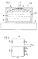
- FIG. 1 the structure of an embodiment of a thermal acceleration and tilt sensor according to the invention is shown schematically.
- a movable object 10 for example a motor vehicle
- the acceleration and inclination of which are detected a dragonfly 11 is attached.
- It comprises a housing 12, which consists of a lower housing part 13 and a cover plate 14.
- the cover plate 14 is attached to the lower housing part 13 so that the housing 12 is completely sealed.
- the housing 12 encloses a rotationally symmetrical cavity 15 which tapers conically towards the cover plate 14.
- the upper part of the cavity 15 has the shape of a truncated cone, the angle of repose of the truncated cone preferably being 21 °.
- a liquid 16 and an air bubble 17 are contained in the cavity 15 enclosed by the housing 12, the liquid 16 and the air bubble 17 jointly completely filling the cavity 15.
- the air bubble 17 lies against the cover plate 14 and extends concentrically around the axis A of the rotationally symmetrical cavity 15.
- the cover plate 14 is designed as a hybrid plate and equipped with electronic components on one side.
- an electrical circuit element RS designed as an ohmic resistance element is applied to the surface side of the cover plate 14 facing the lower housing part 13.
- the electrical circuit element RS formed as an ohmic resistance element is part of a Wheatstone bridge circuit with the resistors RS, RT1, RT2, D1, D2 and D3, which forms the evaluation circuit of the sensor according to FIG.
- a constant DC reference voltage U K is applied to a first bridge diagonal of the Wheatstone bridge circuit.
- the output signal U D of the sensor is taken from the other, second bridge diagonal.
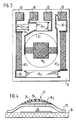
- FIG. 3 shows the cover plate 14 designed as a hybrid plate in a top view of the surface side on which the electrical one Circuit element RS is applied.
- the circuit element RS and the resistors RT1, RT2, D1, D2 and D3 of the evaluation circuit are made in thick-film technology.
- the resistors RT1, RT2, D3 can be used as sensing resistors for the ambient temperature.
- the resistor D3 is used to set the temperature coefficient of the series connection of the resistors RT1, D3, RT2.
- the conductor tracks are designated 19, the connection pads for the external connection of the Wheatstone bridge circuit with 20.
- FIG. 4 shows how the electrically heatable, temperature-sensitive electrical circuit element RS can be constructed in an advantageous manner on the hybrid plate 14 using bubble technology.
- a bladder 21 is arched on the hybrid plate 14 and is made of ceramic material, preferably glass ceramic.
- the resistance element RS designed as a sheet resistor is accommodated in the bladder 21.
- the bladder 21 contains a membrane 23 produced using thick-film technology, on which the resistance element RS is arranged, an intermediate layer 24 consisting of glass being located between the membrane 23 and the resistance element RS.
- the resistance element RS is covered with a good heat-conducting protective layer 25 made of glass.
- the process begins with a platform 26 made of thick film paste being printed on the hybrid plate 14 at the point where the bladder 21 is to be attached and then dried and burned in air.
- a layer of carbon paste is then printed on the pedestal 26, which is then dried and burned in nitrogen.
- the coal paste is burned in nitrogen, essentially only the volatile constituents escape, but the coal remains as solid Receive component.
- a layer consisting of a ceramic thick-film paste is printed on the carbon layer and on an edge region surrounding it, and the system is then fired in nitrogen and then in air.
- the carbon layer burns out completely and the layer applied to the carbon layer bulges out into a membrane.
- the membrane is still too porous and too thin at this stage of the process, it is subsequently reinforced and compacted by incorporating glass.
- the membrane 23 shown in FIG. 4 is produced in this way.
- a glass layer 24 is now printed on the membrane 23. which serves as a base for the resistance element RS to be applied thereon and designed as a sheet resistance and is intended to improve the adhesion and the homogeneity of this resistance element.
- the glass layer 24 can also be omitted.
- a platinum-containing paste is used to produce the resistance element RS.
- the protective layer 25 is then applied.
- the protective layer 25 protects the resistance element RS and the conductor tracks (not shown in FIG. 4) from dirt and corrosion.
- the protective layer 25 is designed so that a good thermal coupling of the temperature of the two media 16 and 17 to the temperature of the resistance element RS is ensured.
- the mode of operation of the sensor according to FIGS. 1 to 4 is as follows:
- the temperature-sensitive electrical circuit element RS heats up to a certain temperature due to the constant reference direct voltage U K applied to the first bridge diagonal of the Wheatstone bridge circuit, at which the temperature-sensitive electrical circuit element RS assumes a certain resistance value. If the sensor is accelerated and / or inclined, then it moves the air bubble 17 to the edge of the housing 12 and the temperature-sensitive electrical circuit element RS is flowed around by the liquid 16. As a result, the temperature of the temperature-sensitive electrical circuit element RS drops and thus also its ohmic resistance value.
- the output signal U D which indicates the acceleration and / or the inclination of the sensor or the moving object, changes on the second bridge diagonal of the Wheatstone bridge circuit.
- the particular advantage of the sensor according to the invention is that there is no abrasion during continuous shaking and only a low hysteresis and that the sensor can be produced inexpensively using hybrid technology.
- the senor can measure omnidirectionally due to the rotationally symmetrical structure of the level and that the liquid does not necessarily have to be transparent.
- the sensor is insensitive to vertical acceleration. Its sensitivity and tendency to respond can be varied over a wide range by the shape of the upper inside of the housing.
- the damping or time behavior of the sensor can be adjusted by the type of liquid and the flow cross-section (distance from floor to lid).
- the platinum resistors RS, RT1 and RT2 have a temperature coefficient TK of 3400 ppm / K
- the thick film resistors D1, D2 and D3 have a temperature coefficient TK of 50 ppm / K.
Landscapes
- Physics & Mathematics (AREA)
- General Physics & Mathematics (AREA)
- Engineering & Computer Science (AREA)
- Radar, Positioning & Navigation (AREA)
- Remote Sensing (AREA)
- Pressure Sensors (AREA)
- Testing Or Calibration Of Command Recording Devices (AREA)
Abstract
Description
- Die Erfindung betrifft einen Sensor nach der Gattung des Anspruchs 1.
- Aus der WO-A-87/05569 ist bereits ein Sensor bekannt, bei dem zur Erfassung der Beschleunigung und der Neigung eines Kraftfahrzeuges ein auf der Brechung oder Reflexion beruhendes optisches Verfahren verwendet wird. Bei diesem Verfahren wird ein von einem Sender ausgehender Lichtstrahl an der Trennfläche Flüssigkeit/Gasblase gebrochen oder reflektiert und trifft auf einen Empfänger, wenn die in dem Gehäuse enthaltene Gasblase sich in ihrer Ausgangslage befindet. Wird die Gasblase dagegen infolge einer Beschleunigung oder einer Neigung des Kraftfahrzeuges von ihrer Ausgangslage ausgelenkt, so wird der Lichtstrahl an der Trennfläche Flüssigkeit/Gasblase in eine andere Richtung gebrochen oder reflektiert und trifft nicht mehr auf den Empfänger, so daß von der optischen Einrichtung ein Signal ausgelöst wird.
- Dieser Sensor hat den Nachteil, daß die zur Realisierung des optischen Verfahrens bereitzustellenden Mittel (Sender, Empfänger usw.) einen relativ hohen Aufwand an mechanischen, optischen und elektrischen Teilen erfordern.
- In US-A- 3 114 209 wird ein Neigungssensor mit einem Gehäuse, das eine Flüssigkeit und eine Luftblase umschließt, beschrieben. Dieser Sensor weist einen Widerstandsdraht auf, der teilweise in der Gasblase und teilweise in der Flüssigkeit gelegen ist. Durch Neigung des Sensorelementes wird die Luftblase derart verschoben, daß der Anteil des Widerstandsdrahtes, der in die Flüssigkeit eintaucht, verändert wird. Die damit verbundene Änderung der Wärmeabführung des Widerstandsdrahtes bewirkt eine Widerstandsänderung, deren Messung eine Aussage über die Neigung des Sensors erlaubt.
- Der erfindungsgemäße Sensor mit den Merkmalen des Anspruchs 1 hat demgegenüber den Vorteil, daß er sehr kostengünstig herzustellen und über einen sehr weiten Temperaturbereich einsetzbar ist. Weitere Vorteile ergeben sich aus den abhängigen Ansprüchen 2 bis 10.
- Anhand der Zeichnung wird die Erfindung näher erläutert.
- Es zeigen:
- Figur 1 einen Querschnitt durch ein Ausführungsbeispiel eines erfindungsgemäßen Sensors mit einer Libelle, schematisch,
- Figur 2 das elektrische Schaltbild einer möglichen Auswerteschaltung des Sensors nach Figur 1,
- Figur 3 die als Hybridplatte ausgebildete Deckelplatte des Gehäuses der Libelle nach Figur 1 mit den darauf befindlichen Schaltungselementen der Auswerteschaltung in der Draufsicht,
- Figur 4 ein in Blasentechnik ausgebildetes elektrisch aufheizbares, temperaturempfindliches elektrisches Schaltungselement im Schnitt senkrecht zu der Oberfläche der als Hybridplatte ausgebildeten Deckelplatte.
- In Figur 1 ist schematisch der Aufbau eines Ausführungsbeispiels eines erfindungsgemäßen thermischen Beschleunigungs- und Neigungssensors dargestellt. An einem beweglichen Gegenstand 10, beispielsweise einem Kraftfahrzeug, dessen Beschleunigung und Neigung erfaßt werden soll, ist eine Libelle 11 befestigt. Sie umfaßt ein Gehäuse 12, das aus einem Gehäuseunterteil 13 und einer Deckelplatte 14 besteht. Die Deckelplatte 14 ist an dem Gehäuseunterteil 13 so befestigt, daß das Gehäuse 12 vollständig dicht ist. Das Gehäuse 12 umschließt einen rotationssymmetrisch ausgebildeten Hohlraum 15, der sich gegen die Deckelplatte 14 hin konisch verjüngt. Der obere Teil des Hohlraums 15 hat dabei die Form eines Kegelstumpfs, wobei der Böschungswinkel des Kegelstumpfs vorzugsweise 21° beträgt. In dem von dem Gehäuse 12 umschlossenen Hohlraum 15 ist eine Flüssigkeit 16 und eine Luftblase 17 enthalten, wobei die Flüssigkeit 16 und die Luftblase 17 den Hohlraum 15 gemeinsam vollständig ausfüllen. In ihrer in Figur 1 dargestellten Ausgangslage liegt die Luftblase 17 an der Deckelplatte 14 an und erstreckt sich konzentrisch um die Achse A des rotationssymmetrisch ausgebildeten Hohlraums 15.
- Die Deckelplatte 14 ist als Hybridplatte ausgebildet und einseitig mit elektronischen Bauelementen bestückt.
- Wie aus der Schnittdarstellung der Figur 1 ersichtlich, ist auf die dem Gehäuseunterteil 13 zugekehrte Oberflächenseite der Deckelplatte 14 ein als ohmsches Widerstandselement ausgebildetes elektrisches Schaltungselement RS aufgebracht.
- Wie aus Figur 2 erkennbar, ist das als ohmsches Widerstandselement ausgebildete elektrische Schaltungselement RS Bestandteil einer Wheatstoneschen Brückenschaltung mit den Widerständen RS, RT₁, RT₂, D₁, D₂ und D₃, die die Auswerteschaltung des Sensors nach Figur 1 bildet. An einer ersten Brückendiagonalen der Wheatstoneschen Brückenschaltung liegt eine konstante Referenzgleichspannung UK an. An der anderen, zweiten Brückendiagonalen wird das Ausgangssignal UD des Sensors abgenommen.
- Figur 3 zeigt die als Hybridplatte ausgebildete Deckelplatte 14 in der Draufsicht auf diejenige Oberflächenseite, auf die das elektrische Schaltungselement RS aufgebracht ist. Das Schaltungselement RS und die Widerstände RT₁, RT₂, D₁, D₂ und D₃ der Auswerteschaltung sind in Dickschichttechnik hergestellt. Die Widerstände RT₁, RT₂, D₃ können als Fühlwiderstände für die Umgebungstemperatur verwendet werden. Der Widerstand D₃ wird dabei dazu benutzt, den Temperaturkoeffizienten der Reihenschaltung der Widerstände RT₁, D₃, RT₂ einzustellen. Die Leiterbahnen sind mit 19, die Anschlußflecken für den äußeren Anschluß der Wheatstoneschen Brückenschaltung mit 20 bezeichnet.
- In Figur 4 ist dargestellt, wie das elektrisch aufheizbare temperaturempfindliche elektrische Schaltungselement RS in vorteilhafter Weise auf der Hybridplatte 14 in Blasentechnik aufgebaut werden kann. Auf der Hybridplatte 14 ist eine Blase 21 aufgewölbt, die aus keramischem Werkstoff, vorzugsweise aus Glaskeramik besteht. In der Blase 21 ist das als Schichtwiderstand ausgebildete Widerstandselement RS untergebracht. Die Blase 21 enthält eine in Dickschichttechnik hergestellte Membran 23, auf der das Widerstandselement RS angeordnet ist, wobei zwischen der Membran 23 und dem Widerstandselement RS sich eine aus Glas bestehende Zwischenschicht 24 befindet. Das Widerstandselement RS ist mit einer gut wärmeleitenden, aus Glas bestehenden Schutzschicht 25 abgedeckt.
- Bei der Herstellung des in Blasentechnik ausgebildeten Widerstandselements RS wird wie folgt verfahren:
- Der Prozeß beginnt damit, daß auf die Hybridplatte 14 an der Stelle, an der die Blase 21 angebracht werden soll, ein aus Dickschichtpaste bestehendes Podest 26 aufgedruckt und anschließend getrocknet und in Luft gebrannt wird. Hierauf wird auf das Podest 26 eine in der Zeichnung nicht dargestellte Schicht aus Kohlepaste gedruckt, die anschließend getrocknet und in Stickstoff gebrannt wird. Beim Brennen der Kohlepaste in Stickstoff entweichen im wesentlichen nur die flüchtigen Bestandteile, die Kohle bleibt jedoch als fester Bestandteil erhalten. Dann wird auf die Kohleschicht und auf einen sie umgebenden Randbereich eine aus einer keramischen Dickschichtpaste bestehende Schicht aufgedruckt und das System anschließend in Stickstoff und hierauf in Luft gebrannt. Beim Brennen des Systems in Luft brennt die Kohleschicht vollständig aus und die auf die Kohleschicht aufgebrachte Schicht wird zu einer Memban aufgewölbt. Da in diesem Verfahrensstand die Membran noch zu porös und zu dünn ist, wird sie anschließend durch Einlagerung von Glas verstärkt und verdichtet. Auf diese Weise entsteht die in Figur 4 dargestellte Membran 23.
- Auf die Membran 23 wird nun eine Glasschicht 24 aufgedruckt. die als Unterlage für das darauf aufzubringende, als Schichtwiderstand ausgebildete Widerstandselement RS dient und die Haftung und die Homogenität dieses Widerstandselements verbessern soll. Bei geeigneter Wahl des Materials für die Membran 23 kann jedoch die Glasschicht 24 auch entfallen.
- Zur Herstellung des Widerstandselements RS wird eine platinhaltige Paste verwendet. Anschließend wird die Schutzschicht 25 aufgetragen. Die Schutzschicht 25 schützt das Widerstandselement RS und die in Figur 4 nicht dargestellten Leiterbahnen vor Verschmutzung und Korrosion. Die Schutzschicht 25 wird so ausgeführt, daß eine gute thermische Ankopplung der Temperatur der beiden Medien 16 und 17 an die Temperatur des Widerstandselements RS gewährleistet ist.
- Die Wirkungsweise des Sensors nach den Figuren 1 bis 4 ist folgende:
- Das temperaturempfindliche elektrische Schaltungselement RS erwärmt sich infolge der an die erste Brückendiagonale der Wheatstoneschen Brückenschaltung angelegten konstanten Referenzgleichspannung UK auf eine bestimmte Temperatur, bei der das temperaturempfindliche elektrische Schaltungselement RS einen bestimmten Widerstandswert annimmt. Wird der Sensor beschleunigt und/oder geneigt, dann wandert die Luftblase 17 zum Rand des Gehäuses 12 und das temperaturempfindliche elektrische Schaltungselement RS wird von der Flüssigkeit 16 umströmt. Dadurch sinkt die Temperatur des temperaturempfindlichen elektrischen Schaltungselementes RS und damit auch dessen ohmscher Widerstandswert. An der zweiten Brückendiagonalen der Wheatstoneschen Brückenschaltung verändert sich das Ausgangssignal UD, das die Beschleunigung und/oder die Neigung des Sensors bzw. des beweglichen Gegenstandes anzeigt.
- Der besondere Vorteil des erfindungsgemäßen Sensors besteht darin, daß kein Abrieb beim Dauerschütteln und nur eine geringe Hysterese auftritt und daß der Sensor kostengünstig in Hybridtechnologie herzustellen ist.
- Vorteilhaft ist des weiteren, daß der Sensor infolge des rotationssymmetrischen Aufbaus der Libelle omnidirektional messen kann und daß die Flüssigkeit nicht notwendigerweise transparent sein muß. Der Sensor ist unempfindlich gegen senkrechte Beschleunigung. Seine Empfindlichkeit bzw. Ansprechneigung ist durch die Formgebung der oberen Gehäuseinnenseite in weiten Bereichen veränderbar. Das Dämpfungs- bzw. Zeitverhalten des Sensors ist durch die Art der Flüssigkeit und den Strömungsquerschnitt (Abstand Boden - Deckel) einstellbar.
- Die aus Platin bestehenden Widerstände RS, RT₁ und RT₂ haben einen Temperaturkoeffizienten TK von 3400 ppm/K, die Dickschichtwiderstände D₁, D₂ und D₃ einen Temperaturkoeffizienten TK von 50 ppm/K.
Claims (10)
- Sensor zur Erfassung der Beschleunigung und der Neigung eines beweglichen Gegenstandes (10), insbesondere eines Kraftfahrzeuges, mit Hilfe einer an dem Gegenstand (10) befestigten Libelle (11), die ein Gehäuse (12), eine in dem Gehäuse (12) befindliche Flüssigkeit (16) und eine in dem Gehäuse (12) befindliche Gasblase (17) umfaßt, wobei die Flüssigkeit (16) und die Gasblase (17) den von dem Gehäuse (12) umschlossenen Hohlraum (15) gemeinsam derart vollständig ausfüllen, daß die Gasblase (17) von der Flüssigkeit (16) nicht vollständig umschlossen wird, sondern an der Innenseite des Gehäuses (12) anliegt, so daß die Trennfläche Flüssigkeit/Gasblase auf die Innenseite des Gehäuses (12) stößt, und wobei die Gasblase (17) sich in dem Gehäuse (12) in einer Ausgangslage befindet, wenn die Beschleunigung und die Neigung der Libelle (11) gleich Null sind oder sich in ihrer Wirkung gegenseitig aufheben, wobei ferner der Sensor ein elektrisch aufheizbares, temperaturempfindliches elektrisches Schaltungselement (RS) aufweist und das elektrische Schaltungselement (RS) Bestandteil einer Auswerteschaltung ist, die ein von der Beschleunigung und der Neigung der Libelle (11) abhängiges Ausgangssignal (UD) abgibt, dadurch gekennzeichnet, daß an der Innenseite des Gehäuses (12) innerhalb desjenigen Bereichs, über den sich die Gasblase (17) in der genannten Ausgangslage erstreckt, das elektrische Schaltungselement (RS) angebracht ist, daß das Gehäuse (12) aus einem Gehäuseunterteil (13) und einer Deckelplatte (14) besteht, daß das elektrische Schaltungselement (RS) an der dem Gehäuseunterteil (13) zugewandten Oberflächenseite der Deckelplatte (14) angebracht ist, und daß das Schaltungselement (RS) auf der als Hybridplatte ausgebildeten Deckelplatte (14) durch Dickschichttechnik erzeugt wurde.
- Sensor nach Anspruch 1, dadurch gekennzeichnet, daß das elektrische Schaltungselement (RS) durch einen durch das elektrische Schaltungselement (RS) fließenden elektrischen Strom aufheizbar ist.
- Sensor nach einem der Ansprüche 1 oder 2, dadurch gekennzeichnet, daß das elektrische Schaltungselement (RS) ein ohmsches Widerstandselement ist.
- Sensor nach Anspruch 3, dadurch gekennzeichnet, daß das ohmsche Widerstandselement (RS) ein Schichtwiderstandselement ist.
- Sensor nach Anspruch 4, dadurch gekennzeichnet, daß das Schichtwiderstandselement (RS) in einer aus keramischem Werkstoff, insbesondere aus Glaskeramik bestehenden Blase (21) untergebracht ist, die an der Innenseite des Gehäuses (12), vorzugsweise an der dem Gehäuseunterteil (13) zugewandten Oberflächenseite der Deckelplatte (14) aufgewölbt ist.
- Sensor nach Anspruch 5, dadurch gekennzeichnet, daß die Blase (21) eine in Dickschichttechnik hergestellte Membran (23) enthält, auf der das Schichtwiderstandselement (RS) angeordnet ist.
- Sensor nach mindestens einem der Ansprüche 1 bis 6, dadurch gekennzeichnet, daß auf die als Hybridplatte ausgebildete Deckelplatte (14) weitere elektrische Schaltungselemente (RT₁, RT₂, D₁, D₂, D₃) aufgebracht sind, die Bestandteil der Auswerteschaltung sind.
- Sensor nach Anspruch 7, dadurch gekennzeichnet, daß die weiteren elektrischen Schaltungselemente (RT₁, RT₂, D₁, D₂, D₃) an der dem Gehäuseunterteil (13) zugewandten Oberflächenseite der Deckelplatte (14) angebracht sind.
- Sensor nach einem der Ansprüche 1 bis 8, dadurch gekennzeichnet, daß der von dem Gehäuse (12) umschlossene Hohlraum (15) mindestens in der Nähe der Ausgangslage der Gasblase (17) die Form eines Kegelstumpfs hat.
- Sensor nach Anspruch 9, dadurch gekennzeichnet, daß der Böschungswinkel des Kegelstumpfs 21° beträgt.
Applications Claiming Priority (3)
| Application Number | Priority Date | Filing Date | Title |
|---|---|---|---|
| DE3939410 | 1989-11-29 | ||
| DE3939410A DE3939410A1 (de) | 1989-11-29 | 1989-11-29 | Sensor |
| PCT/DE1990/000862 WO1991008492A1 (de) | 1989-11-29 | 1990-11-13 | Sensor zur erfassung der beschleunigung und der neigung eines beweglichen gegenstandes, insbesondere eines kraftfahrzeuges |
Publications (2)
| Publication Number | Publication Date |
|---|---|
| EP0501979A1 EP0501979A1 (de) | 1992-09-09 |
| EP0501979B1 true EP0501979B1 (de) | 1994-09-14 |
Family
ID=6394390
Family Applications (1)
| Application Number | Title | Priority Date | Filing Date |
|---|---|---|---|
| EP90916231A Expired - Lifetime EP0501979B1 (de) | 1989-11-29 | 1990-11-13 | Sensor zur erfassung der beschleunigung und der neigung eines beweglichen gegenstandes, insbesondere eines kraftfahrzeuges |
Country Status (5)
| Country | Link |
|---|---|
| US (1) | US5351539A (de) |
| EP (1) | EP0501979B1 (de) |
| JP (1) | JPH05501606A (de) |
| DE (2) | DE3939410A1 (de) |
| WO (1) | WO1991008492A1 (de) |
Families Citing this family (29)
| Publication number | Priority date | Publication date | Assignee | Title |
|---|---|---|---|---|
| DE4016032C2 (de) * | 1990-05-18 | 2000-08-03 | Bosch Gmbh Robert | Sensor |
| GB2296569A (en) * | 1994-12-23 | 1996-07-03 | Monitoring Sys Ltd | Electronic spirit level |
| JP3527590B2 (ja) * | 1996-07-25 | 2004-05-17 | ペンタックス株式会社 | 傾斜センサ、マスク及び天板ホルダ |
| JPH10318747A (ja) * | 1997-05-16 | 1998-12-04 | Asahi Optical Co Ltd | 傾斜センサ |
| US6421622B1 (en) | 1998-06-05 | 2002-07-16 | Crossbow Technology, Inc. | Dynamic attitude measurement sensor and method |
| US6647352B1 (en) | 1998-06-05 | 2003-11-11 | Crossbow Technology | Dynamic attitude measurement method and apparatus |
| US7216055B1 (en) | 1998-06-05 | 2007-05-08 | Crossbow Technology, Inc. | Dynamic attitude measurement method and apparatus |
| US6034594A (en) * | 1998-10-20 | 2000-03-07 | Gray; William R. | Motorcycle warning device |
| US20040215387A1 (en) | 2002-02-14 | 2004-10-28 | Matsushita Electric Industrial Co., Ltd. | Method for transmitting location information on a digital map, apparatus for implementing the method, and traffic information provision/reception system |
| JP3481168B2 (ja) | 1999-08-27 | 2003-12-22 | 松下電器産業株式会社 | デジタル地図の位置情報伝達方法 |
| DE19951195C2 (de) * | 1999-10-22 | 2001-09-27 | Dietrich Braeuer | Einrichtung zur Erfassung der Richtungsänderung bei Zweiradfahrzeugen |
| JP5041638B2 (ja) | 2000-12-08 | 2012-10-03 | パナソニック株式会社 | デジタル地図の位置情報伝達方法とそれに使用する装置 |
| JP4663136B2 (ja) | 2001-01-29 | 2011-03-30 | パナソニック株式会社 | デジタル地図の位置情報伝達方法と装置 |
| JP4230132B2 (ja) | 2001-05-01 | 2009-02-25 | パナソニック株式会社 | デジタル地図の形状ベクトルの符号化方法と位置情報伝達方法とそれを実施する装置 |
| US6851317B2 (en) * | 2002-03-19 | 2005-02-08 | Michael Naumov | Device for measuring horizontal acceleration |
| JP2005178420A (ja) | 2003-12-16 | 2005-07-07 | Honda Motor Co Ltd | 不整地走行用鞍乗り型車両 |
| ES2326984T3 (es) * | 2005-02-23 | 2009-10-22 | Honda Motor Co., Ltd. | Vehiculo todoterreno de tipo de monta en sillin. |
| CN2802441Y (zh) * | 2005-06-17 | 2006-08-02 | 南京德朔实业有限公司 | 便携式倾角测量装置 |
| IL186077A (en) * | 2007-09-19 | 2010-12-30 | Michael Naumov | Method for determining true meridian and device for its implementation |
| US20100251956A1 (en) * | 2009-02-27 | 2010-10-07 | Steven Robert Hilliard | Manual inclinometer systems and methods for preventing motor vehicle crashes |
| EP2420503A1 (de) | 2010-07-27 | 2012-02-22 | Universität Innsbruck | Verfahren zur Herstellung von 14-oxy-substituierten morphinan-6-onen |
| EP2718731B1 (de) | 2011-06-10 | 2021-07-07 | Shockwatch, Inc. | Aufprallindikator |
| US9190229B2 (en) | 2012-05-08 | 2015-11-17 | Shockwatch, Inc. | Impact switch |
| WO2018237324A1 (en) | 2017-06-23 | 2018-12-27 | Shockwatch, Inc. | IMPACT INDICATOR |
| US11046454B2 (en) | 2017-08-01 | 2021-06-29 | Shockwatch, Inc. | Unmanned aerial vehicle impact monitoring system |
| DE102017008208B4 (de) * | 2017-08-31 | 2019-03-21 | Audi Ag | Anordnung zur Ausrichtung von Gegenständen innerhalb eines vorgegebenen Toleranzwinkels |
| US11041770B2 (en) | 2017-10-26 | 2021-06-22 | Shockwatch, Inc. | Impact indicator |
| US11112425B2 (en) | 2019-09-30 | 2021-09-07 | Shockwatch, Inc. | Impact indicator |
| WO2021237150A1 (en) | 2020-05-21 | 2021-11-25 | Shockwatch, Inc. | Impact indicator |
Family Cites Families (7)
| Publication number | Priority date | Publication date | Assignee | Title |
|---|---|---|---|---|
| US3114209A (en) * | 1963-12-17 | Level sensor | ||
| DE2913018A1 (de) * | 1979-03-31 | 1980-10-16 | Bosch Gmbh Robert | Alarmanlage, insbesondere fuer kraftfahrzeuge |
| DE2961608D1 (en) * | 1978-11-02 | 1982-02-11 | Bosch Gmbh Robert | Alarm device, particularly for automotive vehicles |
| IT1179644B (it) * | 1984-05-07 | 1987-09-16 | Marelli Autronica | Dispositivo sensore elettrico di inclinazione e procedimento per la sua fabbricazione |
| DE3609841A1 (de) * | 1986-03-22 | 1987-09-24 | Bosch Gmbh Robert | Sensor zum selbsttaetigen ausloesen von insassenschutzvorrichtungen in fahrzeugen |
| US4771271A (en) * | 1987-03-11 | 1988-09-13 | Ford Motor Company | Silicon based low level liquid sensor having a fast response time |
| DE3829195A1 (de) * | 1988-08-29 | 1990-03-08 | Bosch Gmbh Robert | Temperaturfuehler |
-
1989
- 1989-11-29 DE DE3939410A patent/DE3939410A1/de not_active Withdrawn
-
1990
- 1990-11-13 EP EP90916231A patent/EP0501979B1/de not_active Expired - Lifetime
- 1990-11-13 JP JP2515116A patent/JPH05501606A/ja active Pending
- 1990-11-13 DE DE59007164T patent/DE59007164D1/de not_active Expired - Fee Related
- 1990-11-13 WO PCT/DE1990/000862 patent/WO1991008492A1/de not_active Ceased
- 1990-11-13 US US07/839,757 patent/US5351539A/en not_active Expired - Fee Related
Also Published As
| Publication number | Publication date |
|---|---|
| JPH05501606A (ja) | 1993-03-25 |
| EP0501979A1 (de) | 1992-09-09 |
| DE3939410A1 (de) | 1991-06-06 |
| DE59007164D1 (de) | 1994-10-20 |
| US5351539A (en) | 1994-10-04 |
| WO1991008492A1 (de) | 1991-06-13 |
Similar Documents
| Publication | Publication Date | Title |
|---|---|---|
| WO1991008492A1 (de) | Sensor zur erfassung der beschleunigung und der neigung eines beweglichen gegenstandes, insbesondere eines kraftfahrzeuges | |
| DE3545630C2 (de) | ||
| DE10035263C2 (de) | Optische Vorrichtung | |
| EP0242353B1 (de) | Elektrischer druckgeber mit leckanzeigevorrichtung | |
| DE3781472T2 (de) | Beschleunigungsmesser. | |
| DE3829194A1 (de) | Einrichtung zur messung einer stroemenden luftmenge | |
| DE4102805A1 (de) | Kapazitiver beschleunigungssensor | |
| DE3625842A1 (de) | Druckmesszelle | |
| DE3814950A1 (de) | Beschleunigungsaufnehmer | |
| GB1591157A (en) | Sensing device for liquids | |
| DE4320494C1 (de) | Neigungssensor für ein Fahrzeug | |
| WO1987005569A1 (fr) | Detecteur pour la liberation automatique de dispositifs de protection de passagers dans des vehicules | |
| DE3222591A1 (de) | Messfuehler | |
| EP0221016B1 (de) | Neigungsmessinstrument | |
| DE4016032C2 (de) | Sensor | |
| EP0626061B1 (de) | Messgerät | |
| DE3726146A1 (de) | Vorrichtung zur bestimmung der auf ein fahrzeug wirkenden kraefte | |
| EP0402522B1 (de) | Beschleunigungssensor | |
| DE19752439A1 (de) | Mikromechanischer Neigungssensor, insbesondere für Kraftfahrzeuge | |
| DE10101352B4 (de) | Neigungssensoranordnung | |
| DE19741067A1 (de) | Anordnung zur Erfassung des Füllstandes in einem Flüssigkeitsbehälter | |
| DE4029385C1 (en) | Measuring molten metal level - by calculating difference between reference pressure of container and measured pressure using computer | |
| DE19701704B4 (de) | Vorrichtung zur Angabe des Niveaus einer Fahrzeugachse | |
| DE19510351C1 (de) | Meßanordnung zur Bestimmung der Fließgrenze einer Substanz | |
| DE3404916A1 (de) | Druckgeber |
Legal Events
| Date | Code | Title | Description |
|---|---|---|---|
| PUAI | Public reference made under article 153(3) epc to a published international application that has entered the european phase |
Free format text: ORIGINAL CODE: 0009012 |
|
| 17P | Request for examination filed |
Effective date: 19920411 |
|
| AK | Designated contracting states |
Kind code of ref document: A1 Designated state(s): DE FR GB SE |
|
| 17Q | First examination report despatched |
Effective date: 19931202 |
|
| GRAA | (expected) grant |
Free format text: ORIGINAL CODE: 0009210 |
|
| AK | Designated contracting states |
Kind code of ref document: B1 Designated state(s): DE FR GB SE |
|
| ET | Fr: translation filed | ||
| REF | Corresponds to: |
Ref document number: 59007164 Country of ref document: DE Date of ref document: 19941020 |
|
| GBT | Gb: translation of ep patent filed (gb section 77(6)(a)/1977) |
Effective date: 19941118 |
|
| EAL | Se: european patent in force in sweden |
Ref document number: 90916231.5 |
|
| PLBE | No opposition filed within time limit |
Free format text: ORIGINAL CODE: 0009261 |
|
| STAA | Information on the status of an ep patent application or granted ep patent |
Free format text: STATUS: NO OPPOSITION FILED WITHIN TIME LIMIT |
|
| 26N | No opposition filed | ||
| REG | Reference to a national code |
Ref country code: FR Ref legal event code: D6 |
|
| REG | Reference to a national code |
Ref country code: GB Ref legal event code: 746 Effective date: 19951207 |
|
| PGFP | Annual fee paid to national office [announced via postgrant information from national office to epo] |
Ref country code: GB Payment date: 19981028 Year of fee payment: 9 |
|
| PGFP | Annual fee paid to national office [announced via postgrant information from national office to epo] |
Ref country code: FR Payment date: 19981119 Year of fee payment: 9 |
|
| PGFP | Annual fee paid to national office [announced via postgrant information from national office to epo] |
Ref country code: SE Payment date: 19981124 Year of fee payment: 9 |
|
| PGFP | Annual fee paid to national office [announced via postgrant information from national office to epo] |
Ref country code: DE Payment date: 19990126 Year of fee payment: 9 |
|
| PG25 | Lapsed in a contracting state [announced via postgrant information from national office to epo] |
Ref country code: GB Free format text: LAPSE BECAUSE OF NON-PAYMENT OF DUE FEES Effective date: 19991113 |
|
| PG25 | Lapsed in a contracting state [announced via postgrant information from national office to epo] |
Ref country code: SE Free format text: LAPSE BECAUSE OF NON-PAYMENT OF DUE FEES Effective date: 19991114 |
|
| GBPC | Gb: european patent ceased through non-payment of renewal fee |
Effective date: 19991113 |
|
| EUG | Se: european patent has lapsed |
Ref document number: 90916231.5 |
|
| PG25 | Lapsed in a contracting state [announced via postgrant information from national office to epo] |
Ref country code: FR Free format text: LAPSE BECAUSE OF NON-PAYMENT OF DUE FEES Effective date: 20000731 |
|
| PG25 | Lapsed in a contracting state [announced via postgrant information from national office to epo] |
Ref country code: DE Free format text: LAPSE BECAUSE OF NON-PAYMENT OF DUE FEES Effective date: 20000901 |
|
| REG | Reference to a national code |
Ref country code: FR Ref legal event code: ST |