EP0499809B1 - Chaîne porteuse pour lignes de transport d'énergie - Google Patents
Chaîne porteuse pour lignes de transport d'énergie Download PDFInfo
- Publication number
- EP0499809B1 EP0499809B1 EP92100962A EP92100962A EP0499809B1 EP 0499809 B1 EP0499809 B1 EP 0499809B1 EP 92100962 A EP92100962 A EP 92100962A EP 92100962 A EP92100962 A EP 92100962A EP 0499809 B1 EP0499809 B1 EP 0499809B1
- Authority
- EP
- European Patent Office
- Prior art keywords
- chain
- mounting means
- pins
- guide chain
- chain according
- Prior art date
- Legal status (The legal status is an assumption and is not a legal conclusion. Google has not performed a legal analysis and makes no representation as to the accuracy of the status listed.)
- Expired - Lifetime
Links
Images

Classifications
-
- H—ELECTRICITY
- H02—GENERATION; CONVERSION OR DISTRIBUTION OF ELECTRIC POWER
- H02G—INSTALLATION OF ELECTRIC CABLES OR LINES, OR OF COMBINED OPTICAL AND ELECTRIC CABLES OR LINES
- H02G11/00—Arrangements of electric cables or lines between relatively-movable parts
- H02G11/006—Arrangements of electric cables or lines between relatively-movable parts using extensible carrier for the cable, e.g. self-coiling spring
-
- F—MECHANICAL ENGINEERING; LIGHTING; HEATING; WEAPONS; BLASTING
- F16—ENGINEERING ELEMENTS AND UNITS; GENERAL MEASURES FOR PRODUCING AND MAINTAINING EFFECTIVE FUNCTIONING OF MACHINES OR INSTALLATIONS; THERMAL INSULATION IN GENERAL
- F16G—BELTS, CABLES, OR ROPES, PREDOMINANTLY USED FOR DRIVING PURPOSES; CHAINS; FITTINGS PREDOMINANTLY USED THEREFOR
- F16G13/00—Chains
- F16G13/12—Hauling- or hoisting-chains so called ornamental chains
- F16G13/16—Hauling- or hoisting-chains so called ornamental chains with arrangements for holding electric cables, hoses, or the like
-
- Y—GENERAL TAGGING OF NEW TECHNOLOGICAL DEVELOPMENTS; GENERAL TAGGING OF CROSS-SECTIONAL TECHNOLOGIES SPANNING OVER SEVERAL SECTIONS OF THE IPC; TECHNICAL SUBJECTS COVERED BY FORMER USPC CROSS-REFERENCE ART COLLECTIONS [XRACs] AND DIGESTS
- Y10—TECHNICAL SUBJECTS COVERED BY FORMER USPC
- Y10S—TECHNICAL SUBJECTS COVERED BY FORMER USPC CROSS-REFERENCE ART COLLECTIONS [XRACs] AND DIGESTS
- Y10S59/00—Chain, staple, and horseshoe making
- Y10S59/90—Plastic
Definitions
- the invention relates to an energy guide chain for guiding energy conductors, in particular cables or hoses from a fixed connection to a movable consumer, consisting of a plurality of chain links which consist of two chain links arranged at a distance from one another and parallel to one another and two crossbars connecting the chain links to one another, which at least one cross member is pivotally attached to a link plate about a hinge axis.
- a generic energy chain is known for example from DE-PS 33 18 365.
- This known energy chain consists of a one-piece and dimensionally stable, U-shaped receiving part, the legs of which form outer plates with stops to limit the mutual pivoting angle.
- the outer straps are connected on one side with a cross-piece that is integrally formed, while another cross-piece consists of a separate striker that connects the free ends of the outer straps to one another.
- This striker is articulated with a detachable hinge on an outer plate and lockable with an elastic hook on the other outer plate.
- the hinge consists of an articulated axis exposed in the free edge of an outer plate with a circular cross section flattened perpendicular to the outer plates and rounded narrow sides, and of an undercut formed into the end of the striker provided, cut, part-circular recess. This configuration enables the striker to be non-positively and positively clamped to the hinge axis after it has been slipped onto the hinge axis and pivoted in the direction of the opposite outer link plate.
- This previously known energy chain has proven itself for the management of power lines.
- the energy chain can be easily opened by pivoting the striker so that the energy channel is easily accessible from one side.
- a generic energy chain which consists of a number of articulated chain links, which are designed as injection molded parts made of elastic plastic, each with two side plates and two crossbars. Of these crossbars, at least the upper crossbar is provided on its end faces with latching bodies which can be detachably inserted into corresponding latching body receptacles in the side straps.
- this known energy chain at least part of a swivel joint is arranged in one piece on a crossbar, so that the interior of the individual chain links is accessible only by pivoting this crossbar around the pivot point. Accordingly, the chain links can only be opened if there is sufficient space to pivot the crossbar.
- the invention has for its object to provide a generic energy chain that can be opened at least on both sides, ie on both link plates and allows unhindered access to the energy supply channel, without having to remove the brackets from the link plates Need to become.
- swivel joints arranged on both link plates consist of a pin arranged in the longitudinal direction of the link plates and forming the hinge axis and of a holder which is detachably inserted on the pin, that the holder have an undercut U-shaped recess and that the Traverse is attached to both brackets, the crossbar can be screwed into both brackets.
- the chain links of an energy guiding chain designed according to this technical teaching have the advantage that they can be opened in a simple manner by loosening a holder holding the crossbar from the pin forming the hinge axis and pivoting the crossbar together with the holder around the pin of the second link plate. This type of opening is required if there is sufficient space available to allow the crossbeam to pivot about the pin arranged in the link plate.
- the chain links of an energy chain are opened for maintenance, to supplement or to remove energy conductors.
- the energy supply chain designed according to the invention provides two options for this. On the one hand, the energy supply chain can be opened in the manner described above by pivoting the crossbar.
- the design of the energy supply chain according to the invention has the advantage that the energy supply chain can be offered in the form of a modular system with different traverses. A Subsequent retrofitting of the energy chain with different traverses is possible without replacing or changing the costly to produce swivel joints, which consist of pins integrated in the link plates and brackets attached to these pins.
- the pins are arranged in V-shaped recesses in the link plates, so that the link plates have no parts projecting beyond the outer contour of the energy guide chain due to the integration of the pins.
- the brackets are V-shaped and have a spring clip on the underside with which they can be attached to the pin. This configuration has the advantage that the brackets completely fill the V-shaped recesses in the link plates, so that no contamination can enter the closed energy supply duct. In particular, the entry of metal chips or the like is prevented. Furthermore, it is advantageous in this further development according to the invention that the holders can be simply plugged onto or removed from the pins by means of the spring clips.
- the brackets and the spring clips are preferably made of a plastic that has sufficient elasticity so that the spring clips can still be firmly attached to the pins even after the energy chain has been opened several times and prevents the individual chain links from opening unintentionally.
- the brackets can be pivoted through an angle of more than 90 ° around the pins to the outside of the link plates. With this configuration, the traverse can be pivoted so far that the energy supply channel can be opened wide.
- two pins are arranged on opposite surfaces of recesses in the link plates, the holders having two undercut recesses that fit onto the pins.
- This configuration enables the use of different brackets which are V-shaped or U-shaped depending on the application.
- Another advantage of this embodiment is that the pivoting range of each bracket around the two pins is large.
- this embodiment can also be used with smaller energy chains.
- the brackets have an approach which engages in a corresponding step in the recess of the link plate.
- the traverse can then be attached to the opposite brackets.
- brackets facing the chain link are designed as a circular arc section.
- the brackets of a further embodiment can be pivoted about an angle between 90 ° and 240 °, preferably 180 °, about the pin.
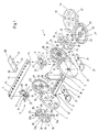
- a chain link 1 consists of two chain links 2 and 3 which are arranged at a distance from one another and parallel to one another and which are connected to one another by cross members 4 and 5.
- the cross-member 4 has a flattened cross-section over its entire length with rounded narrow sides and can be inserted into cut recesses 6 provided with undercuts in the narrow sides of the link plates 2 and 3 and connected to the link plates 2, 3 in a positive and non-positive manner by rotating them about their longitudinal axis.
- the crossmember 5 also has a flattened cross section along its entire length with rounded narrow sides and can be inserted in swivel joints 7 arranged pivotably on the narrow sides of the link plates 2 and 3.
- the swivel joints 7 consist of a pin 8 arranged in one of the link plates 2, 3 and a holder 9 which is pivotably mounted thereon and has a substantially U-shaped recess 10.
- a pin 11 is arranged in this recess 10, in which the crossmember 5 is non-positively and positively connected to the holder 9 by rotation about its longitudinal axis.
- the holder 9 also has on its underside a spring clip 12 with which the holder 9 is inserted onto the pin 8 extending in a recess 13 and in the longitudinal direction of the link plate 2, 3.
- the crossbeams 4 and 5 have a flattened cross-section with rounded narrow sides over their entire length.
- a groove 14 extending in the longitudinal direction of the crossmember 4, 5 is arranged in one side of the crossmembers 4 and 5.
- the cross members 4 and 5 have a multiplicity of bores 15.
- the pins 11 engage in the two outer bores 15 of the cross member 5 when the cross member 5 is screwed into the holder 9, so that the cross member 5 is held immovably transversely to the longitudinal direction of the chain link 1.
- the cross members 4 and 5 can optionally be attached to the link plates 2, 3 in such a way that the grooves 14 are arranged inwards or outwards.
- a separating web 16 is arranged, which is provided at the upper and lower ends with U-shaped holders 17, in which pins 18 are fastened for engagement in the bores 15 of the crossbeams 4, 5.
- the length of the pins 18 corresponds to the depth of the groove 14. In this way, the separating web 16 can be displaced in the longitudinal direction of the cross members 4, 5 when the cross members 4, 5 are fastened with inwardly directed grooves 14. If the grooves 14 of the crossbeams 4, 5 are turned outwards, the pins 18 of the separating web 16 engage in the bores 15 of the crossbeams 4, 5, so that the dividing web 16 cannot be displaced in the longitudinal direction of the crossbeams 4, 5. It is also possible to use a plurality of separating webs 16 between the cross members 4, 5 of a chain link 1.
- skids 19 are releasably attached, which slide on each other when the upper run of an energy chain is supported on the lower run.
- the length of the skids 19 is dimensioned such that the distances between the skids 19 of adjacent link plates 2, 2a are bridged.
- the skids are directly on the lower narrow side of the link plates 2, 3 and indirectly attached to the upper narrow sides of the link plates 2, 3, namely to the holder 9 of the swivel joint 7.
- Each skid 19 is plate-shaped and has on its surface facing away from the narrow sides of the link plates 2, 3 two bevels 20 arranged in the longitudinal direction. On the underside of the skids 19, four locking elements 21 are arranged, which in corresponding recesses 22 on the link plates 2, 3 and are insertable on the brackets 9.
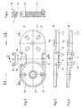
- the mutual swivel angle of adjacent chain links is limited by stop cams 23 and 24 and a stop insert 25.
- the stop cams 24 of the link plate 2 are arranged in a recess 26 of the link plate 2 and aligned in the longitudinal direction of the link plate 2.
- the stop cams 23 at one end of the link plate 2a are arranged in corresponding recesses 26, 27 at 90 ° in comparison to the stop cams 24 at the other end of the same link plate 2a. Accordingly, the connecting line between the stop cams 23 is perpendicular to the longitudinal axis of the chain link 2a, while the other two stop cams 24 lie on the longitudinal axis of the link plate 2a.
- the link plates 2, 3 have an edge 28 encompassing the recess 26, the outer diameter of which is slightly smaller than the inner diameter of the circular recess 27 into which the edge 28 engages.
- the stop inserts 25 have a central bore 32 through which corresponding pins 33 arranged in the recesses 26, 27 engage.
- the link plates 2, 2a of adjacent chain links are connected to one another by means of connecting elements 34, the stop inserts 25 being arranged in the recess 26 or 27 of the link plates 2, 2a in such a way that the slots 29 encompass the stop cam 24, which extends in the radial direction Has recess 26 extending slot 35.
- the stop insert 25 is held non-rotatably in the link plate 2.
- the stop cams 23 are guided in the chain link 2a in the diametrically opposite recesses 30 of the stop insert 25.
- the mutual swivel angle between the chain link 1 and an adjacent chain link shown only by the chain link 2a is limited by the stop surfaces 31a and 31b. Due to the right-angled arrangement of the abutment surfaces 31a to the slots 29 and the formation of the recess 30, the adjacent chain links can only be pivoted in one direction by an angle corresponding to the angle of the recess 30 from an extended position. In order to change the pivoting direction of the chain links relative to one another, it is only necessary to insert the stop inserts 25 into the recesses 26, 27 rotated by 180 ° about one of their axes X or Y.
- the plastic stop inserts 25 have molded-in markings 36, which can be recognized through corresponding openings 37 in the link plates 2, 3, 2a.
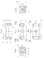
- two pins 39 are arranged on opposite surfaces 38 of the V-shaped recesses 13.
- Brackets 40 are inserted into the V-shaped recesses 13 so as to be pivotable, the brackets 40 each having two undercut recesses 41 that fit onto the pins 39.
- the holder 40 is V-shaped on its side facing the energy guide channel, so that it completely fills the V-shaped recess 13.
- the holder 40 is U-shaped on its side facing the outside of the link plate 2, 2a, 3, so that a gap is arranged between the holder 40 and the V-shaped recess 13.
- the holder 40 has an attachment 42 which engages in a corresponding step 43 in the recess 13. This step serves as a stop surface.
- the holder 40 is shown in detail in FIGS. 7 to 9. It can be seen that part of the underside 44 of the holder 40 facing the chain link 2, 3 is designed as a circular arc section. This circular arc section lies at the end of the holder 40 opposite the attachment 42.
- the recess 41 with an undercut 45 can be seen in FIG. 11.
- the undercuts 45 in the recesses 41 hold the bracket 40 on the pin 39, so that accidental opening of the chain link 1 is avoided.
- An easy opening of the chain link is achieved in that the holder 40 consists of a permanently elastic plastic.
- the elasticity of the holder 40 required when opening and closing the chain link 1 is improved in that slots 46 run parallel to the recesses 41. These slots 46 allow the undercut 45 to escape when the holder 40 is plugged on and when it is pulled off or off the pin 39.
- the holder 40 has an undercut U-shaped recess 10 into which the cross member 5 can be screwed.
- the pin 11 is arranged, which engages in the corresponding bore 15 in the cross member.
- extensions 47 extending in the longitudinal direction of the crossmember are arranged on both sides of the recess 10.
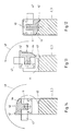
- FIG. 12 shows the link plate 2, 3 with the holder 40 inserted. In this position of the holder 40 shown, the shoulder 42 engages in the step 43.
- the chain link 1 is closed with the cross member 5, not shown in FIG. 13, the pivoting direction of the holder 40 is shown by an arrow 48 at an angle of 90 °.
- an arrow 49 in FIG. 14 shows the pivoting direction of the holder 40, which is now pivoted by 180 ° with respect to the position shown in FIG. 12.
Claims (10)
- Chaîne de guidage d'énergie pour guider des conducteurs d'énergie, en particulier des câbles ou des tuyaux flexibles, d'un raccord fixe à un organe utilisateur mobile, ladite chaîne étant formée d'une pluralité de maillons (1) qui sont constitués de deux flasques (2, 3), disposés à distance l'un de l'autre et parallèlement entre eux, et de deux traverses (4, 5) qui relient les flasques entre eux, au moins une traverse (5) étant fixée à un flasque (2, 3) avec possibilité de pivotement autour d'un axe d'articulation, caractérisée en ce que des articulations tournantes (7) disposées sur les deux flasques (2, 3) sont constituées d'un tourillon (8), qui est disposé dans le sens longitudinal des flasques (2, 3) et qui forme l'axe d'articulation, et d'un support (9) qui est emboîté de manière amovible sur le tourillon (8), en ce que les supports (9) comportent un évidement en U (10) pourvu de décrochements, et en ce que la traverse (5) est fixée à deux supports (9), la traverse (5) pouvant être encastrée par rotation dans les deux supports (9).
- Chaîne de guidage d'énergie selon la revendication 1, caractérisée en ce que les tourillons (8) sont disposés dans des évidements en V (13) des flasques (2, 3).
- Chaîne de guidage d'énergie selon la revendication 1, caractérisée en ce que les supports (9) présentent la forme d'un V et comportent, sur leur face inférieure, un crampon élastique (12) qui permet de les emboîter sur les tourillons (8).
- Chaîne de guidage d'énergie selon la revendication 1, caractérisée en ce que les supports (9) peuvent pivoter selon un angle supérieur à 90° autour des tourillons (8) vers la face extérieure des flasques (2, 3).
- Chaîne de guidage d'énergie selon la revendication 1, caractérisée en ce que deux tourillons (39) sont disposés sur des surfaces en vis-à-vis (38) d'évidements en V (13) des flasques (2, 3), et en ce que les supports (40) comportent deux évidements en décrochement (41) qui s'adaptent sur les tourillons (39).
- Chaîne de guidage d'énergie selon la revendication 5, caractérisée en ce que les supports (40) présentent la forme d'un U.
- Chaîne de guidage d'énergie selon la revendication 6, caractérisée en ce que les supports (40) comportent une pièce rapportée (42) qui s'engage dans un étage correspondant (43) de l'évidement (13).
- Chaîne de guidage d'énergie selon la revendication 5, caractérisée en ce que les faces inférieures (44) des supports (40) tournées vers le flasque (2, 3) ont la forme d'un segment d'arc de cercle.
- Chaîne de guidage d'énergie selon la revendication 1, caractérisée en ce que, dans les évidements (10), est disposée une broche (11) qui s'engage dans un perçage correspondant (15) de la traverse (5).
- Chaîne de guidage d'énergie selon la revendication 5, caractérisée en ce que les supports (40) peuvent pivoter autour des tourillons (8) selon un angle compris entre 90° et 240°, de préférence de 180°.
Applications Claiming Priority (2)
| Application Number | Priority Date | Filing Date | Title |
|---|---|---|---|
| DE4105653A DE4105653A1 (de) | 1991-02-22 | 1991-02-22 | Energiefuehrungskette |
| DE4105653 | 1991-02-22 |
Publications (2)
| Publication Number | Publication Date |
|---|---|
| EP0499809A1 EP0499809A1 (fr) | 1992-08-26 |
| EP0499809B1 true EP0499809B1 (fr) | 1994-12-07 |
Family
ID=6425707
Family Applications (1)
| Application Number | Title | Priority Date | Filing Date |
|---|---|---|---|
| EP92100962A Expired - Lifetime EP0499809B1 (fr) | 1991-02-22 | 1992-01-22 | Chaîne porteuse pour lignes de transport d'énergie |
Country Status (7)
| Country | Link |
|---|---|
| US (1) | US5157913A (fr) |
| EP (1) | EP0499809B1 (fr) |
| JP (1) | JP3010539B2 (fr) |
| KR (1) | KR950007522B1 (fr) |
| AT (1) | ATE115246T1 (fr) |
| DE (2) | DE4105653A1 (fr) |
| ES (1) | ES2066496T3 (fr) |
Cited By (1)
| Publication number | Priority date | Publication date | Assignee | Title |
|---|---|---|---|---|
| DE19820651B4 (de) * | 1998-05-08 | 2007-04-12 | Kabelschlepp Gmbh | Leitungsführungsanordnung mit einer zugentlastenden Befestigung wenigstens einer in der Leitungsführungsanordnung geführten Leitung |
Families Citing this family (25)
| Publication number | Priority date | Publication date | Assignee | Title |
|---|---|---|---|---|
| US5240209A (en) * | 1992-11-17 | 1993-08-31 | Telect, Inc. | Telecommunication multiple cable carrier |
| DE4313075C2 (de) * | 1993-04-21 | 1996-07-25 | Igus Gmbh | Energieführungskette |
| DE4413303C1 (de) * | 1994-04-18 | 1995-05-24 | Kabelschlepp Gmbh | Traverse für eine Energieführungskette |
| DE19523105A1 (de) * | 1995-06-26 | 1997-01-02 | Murrplastik Gmbh | Schließbügel für Kettenglieder einer Energieführungskette |
| DE19645403A1 (de) * | 1996-11-04 | 1998-05-07 | Kabelschlepp Gmbh | Kettenglied und Energieführungskette mit verrastbarer Traverse |
| DE29619833U1 (de) * | 1996-11-14 | 1998-03-19 | Kabelschlepp Gmbh | Befestigungsanordnung mit einem Kettenglied und einer Befestigungseinheit für Leitungen |
| DE19648967A1 (de) * | 1996-11-26 | 1998-06-04 | Kabelschlepp Gmbh | Bausatz für ein an mehrere Anwendungsfälle anpaßbares Kettenglied |
| DE19701706C1 (de) * | 1997-01-21 | 1998-09-03 | Igus Gmbh | Energiezuführungskette |
| DE19839575A1 (de) * | 1998-08-31 | 2000-03-09 | Kabelschlepp Gmbh | Energieführungskette zum Führen von Leitungen mit räumlich beweglichen Kettengliedern |
| DE19957021A1 (de) * | 1999-11-26 | 2001-05-31 | Kabelschlepp Gmbh | Energieführungseinheit |
| US6848369B1 (en) | 2000-05-02 | 2005-02-01 | Haworth, Inc. | Workstation and power and telecommunication arrangement therefor |
| US6448498B1 (en) | 2000-05-02 | 2002-09-10 | Haworth, Inc. | Flexible raceway arrangement for cabling |
| DE10339168A1 (de) | 2003-08-21 | 2005-04-28 | Kabelschlepp Gmbh | Kettenlasche für eine Energieführungskette sowie Energieführungskette |
| DE10346653A1 (de) | 2003-10-08 | 2005-06-09 | Kabelschlepp Gmbh | Kettenlasche, Kettenglied und Energieführungskette, sowie Zwischenstück für eine Energieführungskette, mit torsionsgekoppelten Verriegelungsmitteln zum Verbinden von Quersteg und Kettenlasche |
| DE102004022512A1 (de) * | 2004-05-05 | 2005-12-01 | Kabelschlepp Gmbh | Kettenglied für eine Energieführungskette sowie Energieführungskette mit erweitertem Nutzungsquerschnitt |
| DE102005013430A1 (de) * | 2005-03-21 | 2006-09-28 | Murrplastik Systemtechnik Gmbh | Kettenglied für eine Energieführungskette |
| JP4137117B2 (ja) * | 2005-12-27 | 2008-08-20 | 株式会社椿本チエイン | ケーブル保護案内装置 |
| FR2917912B1 (fr) * | 2007-06-20 | 2010-04-16 | Cqfd Composites | Dispositif de cheminement de cables destine plus particulieremenet au cheminement et a la distribution de cables electriques |
| US20120126067A1 (en) * | 2007-06-20 | 2012-05-24 | Frank Chauzu | Cable routing device |
| JP4751862B2 (ja) * | 2007-08-08 | 2011-08-17 | 株式会社椿本チエイン | ケーブル類保護案内装置 |
| DE102008046700A1 (de) | 2008-09-10 | 2010-03-11 | Murrplastik Systemtechnik Gmbh | Kettenglied für eine Energieführungskette |
| JP5047197B2 (ja) * | 2009-01-07 | 2012-10-10 | 株式会社椿本チエイン | ケーブル類保護案内装置 |
| JP5350445B2 (ja) * | 2011-08-03 | 2013-11-27 | 株式会社椿本チエイン | ケーブル類保護案内装置 |
| DE102016000864A1 (de) * | 2016-01-28 | 2017-08-03 | Murrplastik Systemtechnik Gmbh | Energieführungskette |
| DE202019100877U1 (de) * | 2019-02-15 | 2020-03-17 | Igus Gmbh | Endbefestigungsteil für eine Energieführungskette |
Family Cites Families (10)
| Publication number | Priority date | Publication date | Assignee | Title |
|---|---|---|---|---|
| DE3318365A1 (de) * | 1983-05-20 | 1984-11-22 | Kabelschlepp Gmbh, 5900 Siegen | Energiefuehrungskette |
| US4590961A (en) * | 1985-08-16 | 1986-05-27 | Cooper Industries, Inc. | Modular rolling conductor support |
| DE8528258U1 (de) * | 1985-10-04 | 1985-11-14 | Kabelschlepp Gmbh, 5900 Siegen | Energieführungskette |
| IT209828Z2 (it) * | 1987-01-02 | 1988-11-04 | Mauri Giovanni | Catena portacavi a sviluppo curvilineo.! |
| DE3709740A1 (de) * | 1987-03-25 | 1988-10-06 | Ernst Klein | Einseitig kruemmbare, selbsttragende energiezufuehrungskette |
| US4833876A (en) * | 1987-04-09 | 1989-05-30 | Tsubakimoto Chain Co. | Carrier for cables and the like |
| DE3714056C1 (en) * | 1987-04-28 | 1988-08-25 | Murr Plastik Gmbh | Energy management chain |
| DE8910217U1 (fr) * | 1989-08-26 | 1989-10-05 | Kabelschlepp Gmbh, 5900 Siegen, De | |
| DE9102122U1 (fr) * | 1991-02-22 | 1991-05-16 | Kabelschlepp Gmbh, 5900 Siegen, De | |
| DE9102121U1 (fr) * | 1991-02-22 | 1991-05-16 | Kabelschlepp Gmbh, 5900 Siegen, De |
-
1991
- 1991-02-22 DE DE4105653A patent/DE4105653A1/de not_active Withdrawn
-
1992
- 1992-01-22 AT AT92100962T patent/ATE115246T1/de not_active IP Right Cessation
- 1992-01-22 DE DE59200874T patent/DE59200874D1/de not_active Expired - Fee Related
- 1992-01-22 ES ES92100962T patent/ES2066496T3/es not_active Expired - Lifetime
- 1992-01-22 EP EP92100962A patent/EP0499809B1/fr not_active Expired - Lifetime
- 1992-02-21 KR KR1019920002643A patent/KR950007522B1/ko not_active IP Right Cessation
- 1992-02-21 US US07/839,579 patent/US5157913A/en not_active Expired - Fee Related
- 1992-02-21 JP JP8259892A patent/JP3010539B2/ja not_active Expired - Fee Related
Cited By (1)
| Publication number | Priority date | Publication date | Assignee | Title |
|---|---|---|---|---|
| DE19820651B4 (de) * | 1998-05-08 | 2007-04-12 | Kabelschlepp Gmbh | Leitungsführungsanordnung mit einer zugentlastenden Befestigung wenigstens einer in der Leitungsführungsanordnung geführten Leitung |
Also Published As
| Publication number | Publication date |
|---|---|
| ATE115246T1 (de) | 1994-12-15 |
| KR950007522B1 (ko) | 1995-07-11 |
| KR920016745A (ko) | 1992-09-25 |
| ES2066496T3 (es) | 1995-03-01 |
| DE59200874D1 (de) | 1995-01-19 |
| JPH0599279A (ja) | 1993-04-20 |
| JP3010539B2 (ja) | 2000-02-21 |
| US5157913A (en) | 1992-10-27 |
| EP0499809A1 (fr) | 1992-08-26 |
| DE4105653A1 (de) | 1992-09-03 |
Similar Documents
| Publication | Publication Date | Title |
|---|---|---|
| EP0499809B1 (fr) | Chaîne porteuse pour lignes de transport d'énergie | |
| EP0499791B1 (fr) | Chaise porteuse pour lignes de transport d'énergie | |
| EP0499784B1 (fr) | Chaîne porteuse pour lignes de transport d'énergie | |
| EP0415050B1 (fr) | Chaîne porteuse pour lignes de transport d'énergie | |
| EP0192853B1 (fr) | Chaîne d'amenée d'énergie | |
| EP0126862B1 (fr) | Chaîne de guidage de conducteurs d'énergie | |
| EP1175571B1 (fr) | Chaine de transport d'energie | |
| EP0217086B1 (fr) | Chaîne de guidage de conducteurs d'énergie | |
| EP0956465B1 (fr) | Maillon de chaine a traverse de separation inserable | |
| DE19512088A1 (de) | Energiekette | |
| DE2624429B2 (de) | Klemmittel | |
| DD256902A5 (de) | Energiefuehrungskette | |
| WO2010029090A1 (fr) | Maillon de chaîne pour une chaîne de transmission d'énergie | |
| WO2013124370A2 (fr) | Guide-câble | |
| DE3516448C1 (de) | Energieführungskette | |
| DE3408912C1 (de) | Energieführungskette | |
| EP0308958B1 (fr) | Chaîne porteuse pour lignes de transport d'énérgie | |
| DE102005061775A1 (de) | Kettenglied mit einer Verriegelungseinrichtung | |
| DE2925045C2 (de) | Kettenförderer | |
| EP1705401A2 (fr) | Maillon pour une chaîne porteuse de lignes de transport d'énergie | |
| DE19547215A1 (de) | Regal für Kettenglieder einer Energieführungskette | |
| DE3909797C1 (en) | Energy supply chain for receiving cables and/or lines | |
| EP0724104A1 (fr) | Elément d'atténuation de contraintes et de fixation | |
| EP0557690B1 (fr) | Installation pour mettre en place des éléments pivotants | |
| DE3814995C1 (en) | Self-supporting energy-supply chain which can bend on one side |
Legal Events
| Date | Code | Title | Description |
|---|---|---|---|
| PUAI | Public reference made under article 153(3) epc to a published international application that has entered the european phase |
Free format text: ORIGINAL CODE: 0009012 |
|
| AK | Designated contracting states |
Kind code of ref document: A1 Designated state(s): AT CH DE ES FR GB IT LI NL SE |
|
| 17P | Request for examination filed |
Effective date: 19920721 |
|
| 17Q | First examination report despatched |
Effective date: 19940222 |
|
| GRAA | (expected) grant |
Free format text: ORIGINAL CODE: 0009210 |
|
| AK | Designated contracting states |
Kind code of ref document: B1 Designated state(s): AT CH DE ES FR GB IT LI NL SE |
|
| PG25 | Lapsed in a contracting state [announced via postgrant information from national office to epo] |
Ref country code: NL Effective date: 19941207 |
|
| REF | Corresponds to: |
Ref document number: 115246 Country of ref document: AT Date of ref document: 19941215 Kind code of ref document: T |
|
| REF | Corresponds to: |
Ref document number: 59200874 Country of ref document: DE Date of ref document: 19950119 |
|
| PG25 | Lapsed in a contracting state [announced via postgrant information from national office to epo] |
Ref country code: AT Effective date: 19950122 |
|
| PG25 | Lapsed in a contracting state [announced via postgrant information from national office to epo] |
Ref country code: LI Effective date: 19950131 Ref country code: CH Effective date: 19950131 |
|
| GBT | Gb: translation of ep patent filed (gb section 77(6)(a)/1977) |
Effective date: 19950112 |
|
| ITF | It: translation for a ep patent filed |
Owner name: STUDIO JAUMANN |
|
| REG | Reference to a national code |
Ref country code: ES Ref legal event code: FG2A Ref document number: 2066496 Country of ref document: ES Kind code of ref document: T3 |
|
| PG25 | Lapsed in a contracting state [announced via postgrant information from national office to epo] |
Ref country code: SE Effective date: 19950307 |
|
| ET | Fr: translation filed | ||
| NLV1 | Nl: lapsed or annulled due to failure to fulfill the requirements of art. 29p and 29m of the patents act | ||
| REG | Reference to a national code |
Ref country code: CH Ref legal event code: PL |
|
| PLBE | No opposition filed within time limit |
Free format text: ORIGINAL CODE: 0009261 |
|
| STAA | Information on the status of an ep patent application or granted ep patent |
Free format text: STATUS: NO OPPOSITION FILED WITHIN TIME LIMIT |
|
| 26N | No opposition filed | ||
| PGFP | Annual fee paid to national office [announced via postgrant information from national office to epo] |
Ref country code: ES Payment date: 19990121 Year of fee payment: 8 |
|
| PG25 | Lapsed in a contracting state [announced via postgrant information from national office to epo] |
Ref country code: ES Free format text: LAPSE BECAUSE OF NON-PAYMENT OF DUE FEES Effective date: 20000124 |
|
| REG | Reference to a national code |
Ref country code: ES Ref legal event code: FD2A Effective date: 20010910 |
|
| REG | Reference to a national code |
Ref country code: GB Ref legal event code: IF02 |
|
| PGFP | Annual fee paid to national office [announced via postgrant information from national office to epo] |
Ref country code: GB Payment date: 20030106 Year of fee payment: 12 |
|
| PGFP | Annual fee paid to national office [announced via postgrant information from national office to epo] |
Ref country code: FR Payment date: 20030116 Year of fee payment: 12 |
|
| PGFP | Annual fee paid to national office [announced via postgrant information from national office to epo] |
Ref country code: DE Payment date: 20030205 Year of fee payment: 12 |
|
| PG25 | Lapsed in a contracting state [announced via postgrant information from national office to epo] |
Ref country code: GB Free format text: LAPSE BECAUSE OF NON-PAYMENT OF DUE FEES Effective date: 20040122 |
|
| PG25 | Lapsed in a contracting state [announced via postgrant information from national office to epo] |
Ref country code: DE Free format text: LAPSE BECAUSE OF NON-PAYMENT OF DUE FEES Effective date: 20040803 |
|
| GBPC | Gb: european patent ceased through non-payment of renewal fee |
Effective date: 20040122 |
|
| PG25 | Lapsed in a contracting state [announced via postgrant information from national office to epo] |
Ref country code: FR Free format text: LAPSE BECAUSE OF NON-PAYMENT OF DUE FEES Effective date: 20040930 |
|
| REG | Reference to a national code |
Ref country code: FR Ref legal event code: ST |
|
| PG25 | Lapsed in a contracting state [announced via postgrant information from national office to epo] |
Ref country code: IT Free format text: LAPSE BECAUSE OF NON-PAYMENT OF DUE FEES Effective date: 20050122 |