EP0499487A1 - Verstelleinrichtung für Möbel - Google Patents
Verstelleinrichtung für Möbel Download PDFInfo
- Publication number
- EP0499487A1 EP0499487A1 EP92301250A EP92301250A EP0499487A1 EP 0499487 A1 EP0499487 A1 EP 0499487A1 EP 92301250 A EP92301250 A EP 92301250A EP 92301250 A EP92301250 A EP 92301250A EP 0499487 A1 EP0499487 A1 EP 0499487A1
- Authority
- EP
- European Patent Office
- Prior art keywords
- locking
- assembly
- cam
- actuator
- biasing unit
- Prior art date
- Legal status (The legal status is an assumption and is not a legal conclusion. Google has not performed a legal analysis and makes no representation as to the accuracy of the status listed.)
- Withdrawn
Links
Images


Classifications
-
- A—HUMAN NECESSITIES
- A47—FURNITURE; DOMESTIC ARTICLES OR APPLIANCES; COFFEE MILLS; SPICE MILLS; SUCTION CLEANERS IN GENERAL
- A47C—CHAIRS; SOFAS; BEDS
- A47C1/00—Chairs adapted for special purposes
- A47C1/02—Reclining or easy chairs
- A47C1/031—Reclining or easy chairs having coupled concurrently adjustable supporting parts
- A47C1/032—Reclining or easy chairs having coupled concurrently adjustable supporting parts the parts being movably-coupled seat and back-rest
- A47C1/03205—Reclining or easy chairs having coupled concurrently adjustable supporting parts the parts being movably-coupled seat and back-rest having adjustable and lockable inclination
- A47C1/0325—Reclining or easy chairs having coupled concurrently adjustable supporting parts the parts being movably-coupled seat and back-rest having adjustable and lockable inclination by means of clamps or friction locking members
-
- A—HUMAN NECESSITIES
- A47—FURNITURE; DOMESTIC ARTICLES OR APPLIANCES; COFFEE MILLS; SPICE MILLS; SUCTION CLEANERS IN GENERAL
- A47C—CHAIRS; SOFAS; BEDS
- A47C1/00—Chairs adapted for special purposes
- A47C1/02—Reclining or easy chairs
- A47C1/031—Reclining or easy chairs having coupled concurrently adjustable supporting parts
- A47C1/032—Reclining or easy chairs having coupled concurrently adjustable supporting parts the parts being movably-coupled seat and back-rest
- A47C1/03255—Reclining or easy chairs having coupled concurrently adjustable supporting parts the parts being movably-coupled seat and back-rest with a central column, e.g. rocking office chairs
Definitions
- the invention relates to an adjustment mechanism for furniture, and in particular furniture having at least two parts whose relative position may be adjusted and locked.
- the adjustment mechanism has a locking assembly comprising a locking device for connection between the parts and a biasing unit for the locking device, and an actuator for the biasing unit.
- a swivel chair in which a seat and a backrest are movable with respect to each other, and in which the seat may in turn be movable with respect to a fixed support on a spindle.
- a "scissors" height adjustment mechanism for a collapsible table, or a pivotable height adjustment mechanism for computer furniture is another example.
- such adjustment mechanisms generally comprise a locking device which is usually a friction clutch.
- European Patent Specification No. 0,394,784 Lineager
- PCT Patent Specification No. 86/00508 Volkle
- a biasing spring which acts between a friction clutch and a cam at the end of a handle protruding from the mechanism.
- the cam is rotated using the handle to release pressure of the spring on the friction clutch to allow movement of the various parts.
- problems with this arrangement include the fact that the cam and handle arrangement is bulky, for example, in EP 0,394,784 the spring and cam arrangement protrudes outside of a channel which encloses the clutch and other of the adjustment mechanism.
- British Patent Specification No. GB 2,193,884 (Chair Mechanisms Limited) describes an adjustment mechanism for a chair which is less bulky than those referred to above.
- the friction clutch is clamped in the engaged position by a transversely mounted clamp which is acted upon by a torsion spring.
- the significant disadvantage remains that spring pressure is transmitted through the housing of the mechanism, again leading to reliability problems and more costly construction requirements.
- the invention is characterised in that:- the biasing unit acts between a fixed anchorage in the assembly and the locking device, so that the locking assembly is self-locking, and the actuator is mounted to be functionally separate from the biasing unit in the locked position of the locking assembly.
- the locking assembly is self-locking, stresses are held within the locking assembly and other mechanism components of lower strength than heretofore may be used. Further, there would be very little wear on the actuator because it has to function for the vast majority of the time (while the assembly is locked). Finally, the assembly may be manufactured as a modular unit which may be simply inserted and connected in a mechanism, reducing production costs.
- the actuator comprises a cam rotatable within an external bearing and having a cam surface for engagement with the biasing unit.
- an external bearing allows the cam surface to be located closer to the rotational axis than heretofore, thus increasing mechanical advantage. This is particularly true if the cam surface is formed from a cut-out in the cam.
- the cam may be in the form of a rod mounted transversely of the biasing unit. This is a simple arrangement.
- each locking assembly there may be a cam surface associated with each locking assembly.
- the actuator is not required to provide biasing it may be used for exclusive actuation of locking assemblies, depending on the cam surface configuration. This greatly improves versatility of mechanism control.
- the invention provides a locking assembly for a furniture adjustment mechanism, the assembly comprising:- a housing; a locking device; and a biasing unit acting between the housing and the locking device to hold it in a normally-locked position so that the assembly is self-locking.
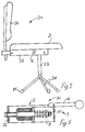
- the adjustment mechanism 1 is for furniture and may be used to allow adjustment of two or three relatively movable parts of an item of furniture, as described below.
- the mechanism 1 comprises a locking assembly 2 and an actuator 3.
- the locking assembly 2 comprises a locking device, namely, a friction clutch 4 having two sets of friction leaves 5(a) and 5(b).
- a bolt 6 protrudes through slots in the leaves 5(a) and 5(b) and at its outer end it carries a nut 7, on the inside of which there is a sleeve 8, and on the inside of which there is a washer 9 engaging the leaves 5(a) and 5(b).
- the bolt 6 also protrudes through an aperture in a channel-shaped housing 11 of the assembly 2, within which there is a biasing unit, namely, a coil spring 12.
- the spring 12 is mounted between the housing 11 and the head of the bolt 6. It thus acts between a fixed anchorage (the housing 11) and the clutch 4 (via the bolt 6, nut 7, sleeve 8 and the washer 9).
- the spring 12 is in compression and urges the head of the bolt 6 away from the clutch leaves 5(a) and 5(b), and hence the washer 9 is urged against the leaves to hold them in position.
- the clutch 4 is normally engaged by the action of the spring 12.
- the locking assembly 2 is self-locking because the spring 12 acts between the clutch 4 and its housing 11. Once the clutch is engaged, the bolt 6 does not move under the action of the spring 12 because the friction leaves 5(a) and 5(b) are clamped in the maximum extent for that spring pressure.
- the locking assembly 2 may be simply inserted into a channel or other housing for an adjustment mechanism without imparting stress on any other parts.
- the adjustment mechanism 1 is completed by the actuator 3 which has a cam, namely, a rod 15 inserted through external bearings, namely, aligned apertures (not shown) in the housing 11.
- a handle 16 is connected at the end of the rod 15.
- the rod 15 has a cut-out which forms a vertical cam surface 17.
- Rotation of the handle 16 into or out of the plane of the page causes the rod 15 to rotate and thus the cam surface 17 contacts the head of the bolt 6 and further rotation compresses the spring 12 and releases pressure on the friction leaves 5(a) and 5(b). Thereafter, furniture parts connected to the leaves 5(a) and 5(b) may be moved in relation to one another because the leaves are free to move.
- the handle 16 is simply released to allow the spring 12 to cause the washer 9 to clamp the leaves at the new position.
- the cam of the actuator need not necessarily be a rod such as the rod 15. It is envisaged that the cam may be much shorter, for example, extending only between the ends of the housing 11. In this case, a handle such as the handle 16′ shown by interrupted lines could be used.
- the actuator includes a cam rotatable in external bearings, and because the cam surface is formed from a cut-out in the cam rod 15, there is a very large mechanical advantage between movement of the handle 16 and movement of the engagement surface 17. Thus, very little movement of the handle 16 is required for disengagement of the clutch 4. Indeed, it is envisaged that a press-in button mechanism could be used instead of a rotatable handle.
- a swivel chair 20 having a seat 21 supported by a seat support 22.
- the seat 20 also has a fixed spindle 23 having legs 24 on casters 25.
- a backrest 26 is pivotally connected to the seat support 22.
- a chair adjustment mechanism 30 which includes the seat support 22 is described.
- a pin 31 is inserted through the ends of the clutch leaves 5(a), the pin 31 being on a fixed support 32 secured to the spindle 23 at an aperture 33.
- the seat support 22 is a channel-shaped member which is pivotally connected to the fixed support 32 by a pivot pin 34.
- the housing 11 of the locking assembly 2 is welded to the seat support 22.
- the clutch leaves 5(b) are connected to a pin 35 in a backrest support 36 having an aperture 37 for reception of the stem of the backrest 26.
- the backrest support 36 is pivotally connected to the seat support 22 directly below the pin 35, and thus is not illustrated.
- the locking assembly 2 is fixed to the seat support 22, and the fixed support 32 and the backrest support 36 are movable in relation to it.
- Fig. 4 there is shown a cross-sectional view of the rod 15 at the locking assembly 2.
- the view of Fig. 5 clearly shows the manner in which the cam surface 17 of the rod 15 engages the bolt 6 to release clamping pressure on the friction leaves 5(a) and 5(b) on rotation of the handle 16.
- the action of the spring 12 causes the friction leaves 5(a) and 5(b) to be clamped together and thus, the fixed support 32, the seat support 22 and the backrest support 36 are fixed in relative position. Effectively, the backrest support 36 is fixed in relation to the seat support, which is in turn fixed in relation to the fixed support 32.
- the handle 16 is pulled either upwardly or downwardly, causing the cam surface 17 to engage the bolt 6, causing the spring 12 to be compressed, releasing pressure on the clutch 4 and allowing the various parts to be moved in relation to one another.
- the chair adjustment mechanism 30 is extremely compact and has few parts. Stresses are not transmitted to the actuator 3 because it is just beyond the bolt 6 and thus, the seat support 32 is not required to handle stresses. Manufacture of the chair adjustment mechanism 30 is relatively simple because the locking assembly may be simply inserted in the seat support 22 and thereafter, the leaves connected to the various pins and the handle 11 welded to the channel. Thus, because the locking assembly is self-contained, not only are stresses not transmitted to the other parts of the adjustment mechanism, but assembly may be carried out in a modular fashion.
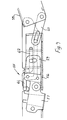
- FIG. 6 there is illustrated a chair adjustment mechanism 40 having two locking assemblies 41 and 42 having friction leaves 43 and 44, respectively. Parts similar to those described with reference to the previous drawings are identified by the same reference numerals. Because there are two locking assemblies 41 and 42, independent adjustment of the seat support in relation to the fixed support and of the backrest support in relation to the seat support is possible. However, to achieve this, there is no need for two actuating mechanisms and instead an actuator 45 having a rod 46 and a handle 47 is used. The rod 46 is mounted in external bearings formed by aligned apertures in a housing 50 of the locking assemblies 41 and 42.
- the rod 46 is machined at the position of the locking assembly 41 as shown in Fig. 7 and at the position of the locking assembly 42 as shown in Fig. 8. At the position of the locking assembly 41 there is a cam surface 48 which is similar to the upper portion of the cam surface 17. However, below the cam surface 48, the rod 46 is tapered. On the contrary, at the position next to the locking assembly 42, the lower part of the rod 46 has a cam surface 49, the upper part being tapered. Thus, rotation of the handle 47 upwardly (out of the plane of the page) causes the cam engagement surface 48 to rotate and disengage the locking assembly 41. However, because of the tapered portion next to the locking assembly 42, this direction of rotation of the rod 46 does not result in its engagement with the assembly 42.
- cam surface and tapered surface may be used to achieve the desired actuation.
- one cam surface may be like the surface 17, the other like the surface 48, so that rotation of the handle in one direction releases both clutches, and in the other direction only one clutch.
- the invention thus provides complete versatility in locking device control.
- a chair adjustment mechanism 55 having a seat support 56, a fixed support 57 and a backrest support 58.
- the two locking assemblies are controlled by separate actuators 61 and 62.
- This arrangement illustrates clearly the compactness of the adjustment mechanism of the invention because although there are two locking assemblies in this arrangement and a separate actuator for each locking assembly, all of the parts of the mechanism may be easily contained within a single channel piece.
- the invention is not limited to the embodiments hereinbefore described.
- the adjustment mechanism has been primarily illustrated for use with chairs, it will be appreciated that it could be used for any type of furniture adjustment.
- One example is a scissors arrangement for adjusting height of a table, or of any type of height adjustment mechanism for a table such as a computer table.
- the advantages of compactness, simplicity, reliability and versatility are achieved irrespective of the use to which the adjustment mechanism is put.
Landscapes
- Health & Medical Sciences (AREA)
- Dentistry (AREA)
- General Health & Medical Sciences (AREA)
- Chairs Characterized By Structure (AREA)
- Chairs For Special Purposes, Such As Reclining Chairs (AREA)
Applications Claiming Priority (4)
| Application Number | Priority Date | Filing Date | Title |
|---|---|---|---|
| IE52691A IE66891B1 (en) | 1991-02-15 | 1991-02-15 | An adjustment mechanism for furniture |
| IE52691 | 1991-02-15 | ||
| IE172491 | 1991-05-21 | ||
| IE172491 | 1991-05-21 |
Publications (1)
| Publication Number | Publication Date |
|---|---|
| EP0499487A1 true EP0499487A1 (de) | 1992-08-19 |
Family
ID=26318921
Family Applications (1)
| Application Number | Title | Priority Date | Filing Date |
|---|---|---|---|
| EP92301250A Withdrawn EP0499487A1 (de) | 1991-02-15 | 1992-02-14 | Verstelleinrichtung für Möbel |
Country Status (6)
| Country | Link |
|---|---|
| US (1) | US5423595A (de) |
| EP (1) | EP0499487A1 (de) |
| AU (1) | AU653199B2 (de) |
| BE (1) | BE1003619A6 (de) |
| GB (1) | GB2252725B (de) |
| IE (1) | IE66891B1 (de) |
Cited By (5)
| Publication number | Priority date | Publication date | Assignee | Title |
|---|---|---|---|---|
| WO1995000051A1 (en) * | 1993-06-28 | 1995-01-05 | Super Sagless Corporation | Chair control mechanism |
| US5863099A (en) * | 1995-02-15 | 1999-01-26 | Ashfield Engineering Company Wexford Limited | Actuator for a chair mechanism lock |
| WO1999009861A1 (en) * | 1997-08-25 | 1999-03-04 | Sylve Moheim | Working chair |
| WO2000003622A1 (de) * | 1998-07-15 | 2000-01-27 | Sifa Sitzfabrik Gmbh | Klemmung für sitzträger von stühlen |
| US7411861B2 (en) | 2005-06-30 | 2008-08-12 | Seiko Epson Corporation | Integrated circuit device and electronic instrument |
Families Citing this family (13)
| Publication number | Priority date | Publication date | Assignee | Title |
|---|---|---|---|---|
| WO1996011611A1 (de) * | 1994-10-17 | 1996-04-25 | Sifa Sitzfabrik Gmbh | Sitzträger für bürostühle oder dergleichen |
| US5676425A (en) * | 1996-03-19 | 1997-10-14 | R.A.M. Machines (1990) Ltd. | Releasable lock forchair control mechanism |
| US5664834A (en) * | 1996-10-08 | 1997-09-09 | Hsu; Hsiu-Lan | Adjusting device of a chair |
| CA2246021A1 (en) * | 1997-08-29 | 1999-02-28 | Leggett & Platt Canada Co./Societe Leggett & Platt Canada | Chair tilt mechanism |
| US6378943B1 (en) | 1999-03-26 | 2002-04-30 | Northfield Metal Products Ltd. | Chair tilt lock mechanisms |
| US6394550B1 (en) * | 2001-08-17 | 2002-05-28 | Gen-Fong Liu | Chair adjustment assembly |
| US6467845B1 (en) * | 2001-09-21 | 2002-10-22 | Su-Ming Chen | Chair with a locking unit |
| US7017992B2 (en) * | 2003-02-18 | 2006-03-28 | Warvel Products, Inc.-N.C. | Chair control device for a tiltable chair |
| US6644743B1 (en) * | 2003-03-04 | 2003-11-11 | Chang-Chen Lin | Chair chassis |
| US20040189073A1 (en) * | 2003-03-28 | 2004-09-30 | Donald Chadwick | Adjustable chair |
| TW200950726A (en) * | 2008-06-06 | 2009-12-16 | Fon Chin Ind Co Ltd | Front-and-back reciprocating, reclining, lifting and lowering apparatus for a chair back |
| CA2978966A1 (en) * | 2015-03-10 | 2016-09-15 | Hans Johann WABL | Chair adjustment means |
| CN113955007B (zh) * | 2021-11-23 | 2022-10-21 | 南京快轮智能科技有限公司 | 锁紧装置及其在滑板车中的应用 |
Citations (5)
| Publication number | Priority date | Publication date | Assignee | Title |
|---|---|---|---|---|
| EP0022225A1 (de) * | 1979-07-06 | 1981-01-14 | F. Martin Steifensand Sitzmöbel- und Tischfabrik GmbH & Co. KG | Sitzmöbel, insbesondere Bürodrehstuhl |
| DE3409593A1 (de) * | 1983-05-13 | 1984-11-15 | Wiesner - Hager KG, Altheim | Arbeitsstuhl |
| WO1985000734A1 (en) * | 1983-08-09 | 1985-02-28 | Pledge Office Chairs Limited | Tilting mechanism for a chair |
| GB2193884A (en) * | 1986-08-16 | 1988-02-24 | Chair Mechanisms Limited | A tilting mechanism for a chair |
| WO1990014031A1 (en) * | 1989-05-19 | 1990-11-29 | Tridec Iii Corporation | Swivel chair with tiltable seat and a mechanism therefor |
Family Cites Families (16)
| Publication number | Priority date | Publication date | Assignee | Title |
|---|---|---|---|---|
| US1818334A (en) * | 1928-09-03 | 1931-08-11 | Bosch Robert | Brake mechanism |
| CH302349A (de) * | 1952-03-14 | 1954-10-15 | Saurer Ag Adolph | Sitzmöbel mit quer verschiebbarem Sitz und verschwenkbarer Rücklehne. |
| US4062587A (en) * | 1976-01-13 | 1977-12-13 | Herman Miller, Inc. | Back position control device for chairs |
| DE2929428C2 (de) * | 1979-07-20 | 1983-10-20 | Fa. Willibald Grammer, 8450 Amberg | Sitz, insbesondere Bürostuhl |
| EP0045925A1 (de) * | 1980-08-08 | 1982-02-17 | F. Martin Steifensand Sitzmöbel- und Tischfabrik GmbH & Co. KG | Sitzmöbel, insbesondere Bürodrehsessel |
| US4438973A (en) * | 1981-08-04 | 1984-03-27 | La-Z-Boy Chair Company | Swivel chair with brake |
| DE3424756A1 (de) * | 1983-08-12 | 1985-02-28 | Konrad 8501 Burgthann Neumüller | Sitztraeger fuer stuehle, insbesondere arbeitsdrehstuehle |
| DE3425387A1 (de) * | 1984-07-10 | 1986-02-27 | Rolf 7298 Loßburg Völkle | Sitzmoebel mit klemmeinrichtung zum verstellen der neigung von rueckenlehne und/oder sitzteil |
| FI69852C (fi) * | 1984-09-27 | 1986-05-26 | Neste Oy | Cykliskt foerfarande foer framstaellning av en alkaliloesning av cellulosakarbamat foer utfaellning av karbamatet och foeraotervinning av kemikalierna |
| DE3513333A1 (de) * | 1985-04-13 | 1986-10-16 | Konrad 8501 Burgthann Neumüller | Spannmittel fuer buerodrehstuehle |
| DE8627482U1 (de) * | 1986-10-15 | 1989-07-06 | Voelkle, Rolf, 7298 Lossburg, De | |
| GB8713089D0 (en) * | 1987-06-04 | 1987-07-08 | Strong C J | Child safety seat |
| NO166684C (no) * | 1988-07-27 | 1991-08-28 | Ring Mekanikk As | Laaseanordning for stolseter. |
| EP0394784A1 (de) * | 1989-04-27 | 1990-10-31 | Lineager S.R.L. | Klemmvorrichtung zum Verstellen der Sitzneigung, insbesondere für Bürostühle |
| DE3930983C2 (de) * | 1989-09-16 | 1993-09-30 | Rolf Voelkle | Sitzmöbel mit neigungsverstellbarer Sitzfläche |
| US5066069A (en) * | 1990-05-03 | 1991-11-19 | Systems Furniture Company | Chair back and seat adjustment mechanism |
-
1991
- 1991-02-15 IE IE52691A patent/IE66891B1/en not_active IP Right Cessation
- 1991-12-19 BE BE9101160A patent/BE1003619A6/fr not_active IP Right Cessation
-
1992
- 1992-02-14 EP EP92301250A patent/EP0499487A1/de not_active Withdrawn
- 1992-02-14 GB GB9203192A patent/GB2252725B/en not_active Expired - Fee Related
- 1992-02-14 AU AU10963/92A patent/AU653199B2/en not_active Ceased
-
1994
- 1994-02-17 US US08/197,354 patent/US5423595A/en not_active Expired - Fee Related
Patent Citations (5)
| Publication number | Priority date | Publication date | Assignee | Title |
|---|---|---|---|---|
| EP0022225A1 (de) * | 1979-07-06 | 1981-01-14 | F. Martin Steifensand Sitzmöbel- und Tischfabrik GmbH & Co. KG | Sitzmöbel, insbesondere Bürodrehstuhl |
| DE3409593A1 (de) * | 1983-05-13 | 1984-11-15 | Wiesner - Hager KG, Altheim | Arbeitsstuhl |
| WO1985000734A1 (en) * | 1983-08-09 | 1985-02-28 | Pledge Office Chairs Limited | Tilting mechanism for a chair |
| GB2193884A (en) * | 1986-08-16 | 1988-02-24 | Chair Mechanisms Limited | A tilting mechanism for a chair |
| WO1990014031A1 (en) * | 1989-05-19 | 1990-11-29 | Tridec Iii Corporation | Swivel chair with tiltable seat and a mechanism therefor |
Cited By (5)
| Publication number | Priority date | Publication date | Assignee | Title |
|---|---|---|---|---|
| WO1995000051A1 (en) * | 1993-06-28 | 1995-01-05 | Super Sagless Corporation | Chair control mechanism |
| US5863099A (en) * | 1995-02-15 | 1999-01-26 | Ashfield Engineering Company Wexford Limited | Actuator for a chair mechanism lock |
| WO1999009861A1 (en) * | 1997-08-25 | 1999-03-04 | Sylve Moheim | Working chair |
| WO2000003622A1 (de) * | 1998-07-15 | 2000-01-27 | Sifa Sitzfabrik Gmbh | Klemmung für sitzträger von stühlen |
| US7411861B2 (en) | 2005-06-30 | 2008-08-12 | Seiko Epson Corporation | Integrated circuit device and electronic instrument |
Also Published As
| Publication number | Publication date |
|---|---|
| IE66891B1 (en) | 1996-02-07 |
| AU653199B2 (en) | 1994-09-22 |
| GB9203192D0 (en) | 1992-04-01 |
| GB2252725B (en) | 1995-04-19 |
| GB2252725A (en) | 1992-08-19 |
| BE1003619A6 (fr) | 1992-05-05 |
| US5423595A (en) | 1995-06-13 |
| IE910526A1 (en) | 1992-08-26 |
| AU1096392A (en) | 1992-08-20 |
Similar Documents
| Publication | Publication Date | Title |
|---|---|---|
| EP0499487A1 (de) | Verstelleinrichtung für Möbel | |
| US3127788A (en) | Position-retaining device | |
| US4640484A (en) | Support column with gravity dependent retention means | |
| US8113076B2 (en) | Mechanical positioner for reclining seat assembly | |
| US7708346B2 (en) | Reclining back mechanism for a seating unit | |
| EP0185726B1 (de) | Verbesserungen an regelbaren teleskopischen vorrichtungen | |
| US5527095A (en) | Pawl and ratchet assembly | |
| WO2001040700A1 (en) | Articulated arm system for attaching different medical imaging devices to support structures in an articulated manner | |
| JPS6365818A (ja) | ガス圧ばねを備えた高さ調節可能な回転椅子 | |
| CA1250516A (en) | Adjustable office chair | |
| GB2034178A (en) | Ergonomic chair | |
| IE66531B1 (en) | A chair tilting mechanism | |
| US5188345A (en) | Lockable elevating mechanism for the continuous adjustment of chair seats | |
| TWI690286B (zh) | 家具件及調整組件,特別用於調整椅背 | |
| US5356200A (en) | Unitary brake for a chair tilt mechanism | |
| GB2304172A (en) | A support column having height and angular position return means | |
| US4613106A (en) | Mechanical adjustable column | |
| US6688190B2 (en) | Manual lever drive for adjusting devices on seats, in particular, motor vehicles seats | |
| CZ286553B6 (cs) | Nosná konstrukce pro kancelářské židle a podobný sedací nábytek | |
| US7147282B2 (en) | Chair with backrest depth adjustment mechanism | |
| US5676425A (en) | Releasable lock forchair control mechanism | |
| EP0902634B1 (de) | Vorrichtung zum einstellen des neigungswinkels der sitzflächen im allgemeinen | |
| US20010013569A1 (en) | Inclinable support for chair | |
| EP0871383B1 (de) | Verstellvorrichtung für die neigung einer rückenstütze bezüglich eines sitzteils bei stühlen | |
| EP0796576B1 (de) | Mechanische Fernbedienungsanordnung mit Drucktastenschalter mit niedrigem Profil |
Legal Events
| Date | Code | Title | Description |
|---|---|---|---|
| PUAI | Public reference made under article 153(3) epc to a published international application that has entered the european phase |
Free format text: ORIGINAL CODE: 0009012 |
|
| AK | Designated contracting states |
Kind code of ref document: A1 Designated state(s): AT BE CH DE DK ES FR GB GR IT LI LU MC NL PT SE |
|
| 17P | Request for examination filed |
Effective date: 19930218 |
|
| 17Q | First examination report despatched |
Effective date: 19950324 |
|
| RAP1 | Party data changed (applicant data changed or rights of an application transferred) |
Owner name: ASHFIELD ENGINEERING COMPANY WEXFORD LIMITED |
|
| STAA | Information on the status of an ep patent application or granted ep patent |
Free format text: STATUS: THE APPLICATION IS DEEMED TO BE WITHDRAWN |
|
| 18D | Application deemed to be withdrawn |
Effective date: 19951005 |