EP0495268B1 - Eisenbahnoberbau und Betonschwelle - Google Patents
Eisenbahnoberbau und Betonschwelle Download PDFInfo
- Publication number
- EP0495268B1 EP0495268B1 EP91250323A EP91250323A EP0495268B1 EP 0495268 B1 EP0495268 B1 EP 0495268B1 EP 91250323 A EP91250323 A EP 91250323A EP 91250323 A EP91250323 A EP 91250323A EP 0495268 B1 EP0495268 B1 EP 0495268B1
- Authority
- EP
- European Patent Office
- Prior art keywords
- sleeper
- concrete
- sleepers
- supporting
- rails
- Prior art date
- Legal status (The legal status is an assumption and is not a legal conclusion. Google has not performed a legal analysis and makes no representation as to the accuracy of the status listed.)
- Expired - Lifetime
Links
- 241001669679 Eleotris Species 0.000 title claims abstract description 33
- 239000004567 concrete Substances 0.000 title claims abstract description 29
- 230000005484 gravity Effects 0.000 claims abstract description 4
- 238000005452 bending Methods 0.000 claims description 3
- 238000010276 construction Methods 0.000 claims 1
- 238000009434 installation Methods 0.000 claims 1
- 241001660693 Trapezia Species 0.000 abstract 1
- 238000006073 displacement reaction Methods 0.000 description 6
- 238000005516 engineering process Methods 0.000 description 2
- 239000000463 material Substances 0.000 description 2
- 229910000831 Steel Inorganic materials 0.000 description 1
- 239000010426 asphalt Substances 0.000 description 1
- 239000004568 cement Substances 0.000 description 1
- 238000011161 development Methods 0.000 description 1
- 230000018109 developmental process Effects 0.000 description 1
- 230000000694 effects Effects 0.000 description 1
- 230000002349 favourable effect Effects 0.000 description 1
- 239000000835 fiber Substances 0.000 description 1
- 238000004519 manufacturing process Methods 0.000 description 1
- 239000000203 mixture Substances 0.000 description 1
- 239000002986 polymer concrete Substances 0.000 description 1
- 238000005086 pumping Methods 0.000 description 1
- 239000011150 reinforced concrete Substances 0.000 description 1
- 230000002787 reinforcement Effects 0.000 description 1
- 239000007787 solid Substances 0.000 description 1
- 239000010959 steel Substances 0.000 description 1
- 239000003351 stiffener Substances 0.000 description 1
Images


Classifications
-
- E—FIXED CONSTRUCTIONS
- E01—CONSTRUCTION OF ROADS, RAILWAYS, OR BRIDGES
- E01B—PERMANENT WAY; PERMANENT-WAY TOOLS; MACHINES FOR MAKING RAILWAYS OF ALL KINDS
- E01B3/00—Transverse or longitudinal sleepers; Other means resting directly on the ballastway for supporting rails
- E01B3/28—Transverse or longitudinal sleepers; Other means resting directly on the ballastway for supporting rails made from concrete or from natural or artificial stone
Definitions
- the invention relates to a railway superstructure and a concrete sleeper according to the preambles of claims 1 and 4.
- FR-PS 434 048 For better load distribution it was already proposed in FR-PS 434 048 to arrange simple rod-shaped cross sleepers made of reinforced concrete at an angle to the rails in such a way that the axle load of the vehicles is distributed over two sleeper supports, i.e. the sleepers overlap by about 50 percent in the longitudinal direction of the rail .
- the load distribution that is unnecessary with today's common materials increases the threshold length by more than 1/10 without any significant effect.
- Angle thresholds (DE-OS 24 01 329) should serve to allegedly increase the transverse displacement resistance. It was overlooked that the main displacement resistance is created by gravel in front of the head surfaces of the sleepers.
- the invention is based on the problem of optimizing the known railway superstructure systems with regard to the bending load on the rails, the distribution of the bearing load and the improvement of the mounting options when the components are used universally.
- the invention is based on the knowledge that In principle, Y-sleepers would be suitable for the railway superstructure both in ballast bedding and on firm ground with regard to their layability and operational resilience. While maintaining the system of supports offset in the longitudinal direction of the rails on the sleeper ends, a middle way between conventional concrete cross sleepers and Y sleepers in concrete was found by placing the concrete sleeper axis practically at an angle to the travel path. The support areas were chosen so that the high transverse displacement resistance of the track system known at Y sleepers is maintained. This is achieved, among other things, by the fact that the offset bearing areas of a threshold have a large head area overall.
- the effective head surfaces facing the middle of the track also make it possible to significantly reduce the amount of ballast that is required for a high resistance to displacement before the sleeper ends. This makes the entire route narrower and cheaper.
- the support areas can be offset from one another by a third or more of a threshold division. In the optimal case, the sleepers, measured in the longitudinal direction of the rail, are so wide that they fill an entire sleeper division. In practice, the entire lateral projection surface of a threshold is available as a resistance surface against transverse displacement.
- Such a railway superstructure with uniform concrete sleepers in an inclined position can practically no longer be displaced transversely, since the operating load emanating from a vehicle axle, for example as centrifugal force when cornering, acts at an angle to the sleeper axle and thus reduces the resulting transverse displacement forces.
- the concrete sleeper can be used universally, as it is always identical to neighboring sleepers. It is not axisymmetric, but point symmetrical relative to the centroid of the threshold. In conjunction with the proven double support technology and the relatively wide support area of the sleeper, the result is a rigid track system, the individual elements of which are not so heavy, however, that they cannot be handled relatively easily in terms of assembly technology. Subsequent correction of the rail position, tamping the sleepers, replacing the sleepers or similar work can be carried out just as easily as with conventional concrete sleepers.
- the concrete sleeper shape is composed of geometrically regular sections.
- the middle part of the threshold the connection between the two support areas, has been dimensioned to the minimum dimension that is computationally possible from bending load and torsion. This meets the requirement for the broadest possible support areas under the rails and the lowest possible weight of the concrete sleepers.
- suitable materials such as B. polymer concrete, compositions of concrete with torsion-stiffening agents such as GRP fibers and using colloidal cement, the element stiffness can be increased and additional weight can be saved.
- Fig. 1 two rails 1, 2 are mounted on four sleepers 3 of a railway superstructure.
- the thresholds 3 have trapezoidal support areas 4, 6, which are formed point-symmetrically to the center of gravity M of the threshold on the narrower central part 5.
- a double support 8, 9 for the mounting of the rails 1, 2 is assigned to each support area 4, 6.
- the rail foot is fixed in the established tension by means of fastening elements 10 arranged centrally between the double supports 8, 9.
- the rail fastenings are offset by half a sleeper division (T / 2) in the longitudinal direction of the rail.
- the total width of the threshold 3 corresponds to the threshold division T.
- the ratio of the support lengths L1, L2 to the total length L of the threshold is important.
- the sloping axial position of the sleeper also increases the effective sleeper length.
- the trapezoidal design of the support areas supports the demand for the lowest possible surface load due to the operational load on the track system.
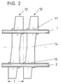
- the threshold division T corresponds to the calculated overall width of the threshold 12.
- the threshold 18 is composed of individual partly overlapping cuboid or truncated pyramid-shaped segments with an integrated central part 15.
Landscapes
- Engineering & Computer Science (AREA)
- Architecture (AREA)
- Civil Engineering (AREA)
- Structural Engineering (AREA)
- Machines For Laying And Maintaining Railways (AREA)
- Railway Tracks (AREA)
- Road Paving Structures (AREA)
- Lining And Supports For Tunnels (AREA)
- Road Signs Or Road Markings (AREA)
- Laminated Bodies (AREA)
Description
- Die Erfindung betrifft einen Eisenbahnoberbau und eine Betonschwelle gemäß den Oberbegriffen der Ansprüche 1 und 4.
- Es ist ein Eisenbahnoberbau mit Betonquerschwellen als Schienenträger für Schotterbetten oder auch auf festem Beton- oder Asphaltuntergrund bekannt, die je Schwellenende zwei Auflager tragen (DE-Al-36 19 417). Diese Doppelauflager mindern die Schienendurchbiegung und reduzieren die Torsion und damit die bekannte Pumpwirkung der Schwellen in Schotterbetten. Die gleiche Veröffentlichung Zeigt auch Y-Schwellen dieser Bauart bei denen bei gegebenem Nominalabstand der Auflagerpunkte der Schienen (Schwellenteilung) eine noch bessere Lastverteilung erreicht wird und zudem die Betriebsbelastung durch größere Torsionssteifigkeit verringert wird. Derartige Y-Schwellen oder X-Schwellen in Beton mit Einzelauflagern an jedem Schwellendende sind auch bereits mit der DE-Al-28 02 145 veröffentlicht worden. In der Praxis hat es mit derartigen mehrendigen Schwellen Montageprobleme deshalb gegeben, weil die Stückgewichte erheblich größer als bei standardisierten Querschwellen sind.
- Zur besseren Lastverteilung wurde auch schon in der FR-PS 434 048 vorgeschlagen, einfache stabförmige Querschwellen aus armiertem Beton derart schräg zu den Schienen anzuordnen, daß die Achslast der Fahrzeuge auf zwei Schwellenauflager verteilt wird, die Schwellen sich in Schienenlängsrichtung also zu etwa 50 Prozent überlappen. Die bei heute gebräuchlichen Werkstoffen unnötige Lastverteilung erhöhen die Schwellenlänge um mehr als 1/10 ohne wesentlichen Effekt.
- Zur angeblichen Erhöhung des Querverschiebewiderstandes sollten Winkelschwellen (DE-OS 24 01 329) dienen. Dabei wurde übersehen, daß der wesentliche Verschiebewiderstand durch Schotter vor den Kopfflächen der Schwellen erzeugt wird.
- Es wurde ebenfalls schon vorgeschlagen, durch Verwendung sogenannter "Ohrenschwellen" die Zahl der Schwellen zu reduzieren bzw. die Zahl der Schienen-Auflager zu erhöhen (CH-C-40 591). Die seitlich der Schwellenachse sich erstreckenden Betonteile dieser Schwellen brachen aufgrund der Belastung durch die Schienenfahrzeuge in der Praxis jedoch häufig trotz Bewehrung
Außerdem ist aus der US-PS-1,711,186 bekannt, unsymmetrische gekröpfte Schwellen in Doppel-T-Form aus Stahl zickzackförmig zu koppeln, um ein sehr steifes Gleisgefüge zu erhalten.
Aufgrund ihrer Form sind diese Schwellen nur als Kombielemente verwendbar und haben den Nachteil, daß sie sehr exakt gefertigt sein müssen, um eine Schienenlagerung zu ermöglichen. Dies ist insbesondere in Kurvenbereichen und bei Gleisüberhöhungen derart schwierig, daß sie den Geländeverhältnissen angepaßt gefertigt werden müssen und nicht einfach austauschbar sind. - Der Erfindung liegt das Problem zugrunde, die bekannten Eisenbahnoberbausysteme zu optimieren hinsichtlich Biegebelastung der Schienen, Auflagelastverteilung und Verbesserung der Montagemöglichkeiten bei universellem Einsatz der Bauelemente.
- Das Problem wird erfindungsgemäß durch die Ansprüche 1 und 4 gelöst. Vorteilhafte Weiterbildungen der Erfindung sind in den Unteransprüchen beschrieben.
- Die Erfindung geht von der Erkenntnis aus, daß Y-Schwellen prinzipiell bezüglich ihrer Verlegbarkeit und Betriebsbelastbarkeit für den Eisenbahnoberbau sowohl in Schotterbettung als auch auf festem Grund geeignet wären. Unter Beibehaltung des Systems von in Schienenlängsrichtung versetzten Auflagern auf den Schwellenenden wurde ein Mittelweg zwischen üblichen Betonquerschwellen und Y-Schwellen in Beton gefunden, indem die Betonschwellenachse praktisch schräg zum Fahrweg gelegt wurde. Die Auflagerbereiche wurden dabei so gewählt, daß der bei Y-Schwellen bekannt hohe Querverschiebewiderstand der Gleisanlage beibehalten wird. Dies wird unter anderem dadurch erreicht, daß die versetzten Auflagerbereiche einer Schwelle insgesamt eine große Kopffläche aufweisen. Die zur Gleismitte hin gerichteten, wirksamen Kopfflächen ermöglichen es zudem, die Schottermengen, die für einen großen Verschiebewiderstand erforderlich sind, vor den Schwellenenden erheblich zu verringern. Dadurch wird der gesamte Fahrweg schmaler und billiger. Die Auflagerbereiche können um ein Drittel oder mehr einer Schwellenteilung zueinander versetzt sein. Im optimalen Fall sind die Schwellen, gemessen in Schienenlängsrichtung, so breit, daß sie eine ganze Schwellenteilung ausfüllen. Praktisch steht somit die gesamte seitliche Projektionsfläche einer Schwelle als Widerstandsfläche gegen Querverschiebung zur Verfügung.
- Ein derartiger Eisenbahnoberbau mit gleichförmigen Betonschwellen in Schräglage läßt sich praktisch nicht mehr quer verschieben, da die von einer Fahrzeugachse ausgehende Betriebslast, beispielsweise als Fliehkraft in Kurvenüberhöhungen, unter einem Winkel zur Schwellenachse wirkt und damit die resultierenden Querverschiebekräfte mindert.
- Die Betonschwelle ist universell einsetzbar, da sie stets baugleich mit benachbarten Schwellen ist. Sie ist zwar nicht achsensymmetrisch, aber relativ zum Flächenschwerpunkt der Schwelle punktsymmetrisch. In Verbindung mit der bewährten Doppelauflagertechnik und dem relativ breiten Auflagerbereich der Schwelle ergibt sich ein steifes Gleissystem, dessen Einzelelemente aber nicht so schwer sind, daß sie nicht montagetechnisch relativ einfach bewältigt werden können.
Ein nachträgliches Korrigieren der Schienenlage, ein Stopfen der Schwellen, ein Austauschen der Schwellen oder ähnliche Arbeiten lassen sich ebenso problemlos ausführen, wie bei herkömmlichen Betonquerschwellen. - Aus fertigungstechnischen Gründen ist die Betonschwellenform aus geometrisch regelmäßigen Sektionen zusammengesetzt. Dabei ist das Mittelteil der Schwelle, die Verbindung zwischen den beiden Auflagerbereichen, auf das aus Biegebelastung und Torsion rechnerisch mögliche Mindestmaß hin dimensioniert worden. Damit wird der Forderung nach möglichst breiten Auflagerbereichen unter den Schienen und möglichst geringen Gewichten der Betonschwellen Rechnung getragen. Durch Verwendung geeigneter Materialien wie z. B. Polymerbeton, Kompositionen aus Beton mit torsionsversteifenden Mitteln wie GFK-Fasern und unter Verwendung von kolloidalem Zement läßt sich die Elementsteifigkeit erhöhen und weiteres Gewicht einsparen.
- Anhand schematischer Zeichnungen soll die Erfindung näher erläutert werden. Es zeigen
- Figur 1
- eine Draufsicht auf eine Gleisanlage mit vier erfindungsgemäßen Betonschwellen,
- Figur 2
- eine zweite Ausführungsform mit zwei erfindungsgemäßen Betonschwellen,
- Figur 3
- eine dritte Ausführungsform der erfindungsgemäßen Betonschwelle.
- In Fig. 1 sind zwei Schienen 1, 2 auf vier Schwellen 3 eines Eisenbahnoberbaus gelagert. Die Schwellen 3 weisen trapezförmige Auflagerbereiche 4, 6 auf, die punktsymmetrisch zum Flächenschwerpunkt M der Schwelle auf dem schmaleren Mittelteil 5 ausgebildet sind. Jedem Auflagerbereich 4, 6 ist ein Doppelauflager 8, 9 für die Lagerung der Schienen 1, 2 zugeordnet. Der Schienenfuß ist durch mittig zwischen den Doppelauflagern 8, 9 angeordnete Befestigungselemente 10 in bewährter Spannung fixiert. Bei den dargestellten Schwellenformen sind die Schienenbefestigungen um ein Halb mal Schwellenteilung (T/2) in Schienenlängsrichtung versetzt. Die Gesamtbreite der Schwelle 3 entspricht der Schwellenteilung T. Für die Berechnung der Lastverteilung im Eisenbahnoberbau ist das Verhältnis der Auflage-Längen L1, L2 zur Gesamtlänge L der Schwelle wichtig. Durch die schräge Achslage der Schwelle erhöht sich auch die wirksame Schwellenlänge. Die trapezförmige Ausbildung der Auflagerbereiche unterstützt die Forderung nach möglichst geringer Flächenbelastung durch die Betriebsbelastung der Gleisanlage.
- Fig. 2 zeigt schematisch eine Draufsicht auf zwei in der Gleisanlage liegende erfindungsgemäße Betonquerschwellen 12 bei denen speziell die Auflagerbereiche 11, 13 beidseits des Mittelteiles 14 unter den Schienen 1, 2 extrem breit ausgebildet sind. Auch hierbei entspricht die Schwellenteilung T der rechnerischen Gesamtbreite der Schwelle 12.
- Eine ähnliche günstige Breite der Auflager 16, 17 für die Schienen 1, 2 läßt sich erreichen, wenn gemäß Fig. 3 die Schwelle 18 aus einzelnen sich teils überlappenden quader- oder pyramidenstumpfförmigen Segmenten mit integriertem Mittelteil 15 zusammengesetzt wird.
Claims (7)
- Eisenbahnoberbau aus einzeln angeordneten, sich nicht überlappenden Betonschwellen, die an ihren beiden Enden je einen Auflagerbereich zur Schienenlagerung aufweisen, dadurch gekennzeichnet, daß die Auflagerbereiche (4, 6; 11, 13; 16, 17) einer Betonschwelle (3, 12, 18) in Schienenlängsrichtung zueinander versetzt sind und zur Gleismitte gerichtete Kopfflächen aufweisen, wobei die Auflagerbereiche (4, 6; 11, 13; 16, 17) durch ein schmaleres Mittelteil (5, 14, 15) unsymmetrisch zur Gleismitte und zum Flächenschwerpunkt (M) der Schwelle symmetrisch verbunden sind.
- Eisenbahnoberbau nach Anspruch 1, dadurch gekennzeichnet, daß die Auflagerbereiche um jeweils ein Drittel bis zur Hälfte einer Schwellenteilung (T) versetzt sind.
- Eisenbahnoberbau nach Anspruch 1, dadurch gekennzeichnet, daß die in Schienenlängsrichtung gemessene Gesamtbreite der Betonschwellen (3, 12, 18) etwa der Schwellenteilung (T) entspricht.
- Betonschwelle, insbesondere für einen Eisenbahnoberbau nach den Ansprüchen 1 bis 3, in gegen Torsion- und Biegebruch widerstandsfähiger Bauweise mit je einem Auflagerbereich an beiden Enden für die Schienen einer Gleisanlage, dadurch gekennzeichnet, daß die Auflagerbereiche (4, 6;11, 13; 16, 17) durch ein schmaleres Mittelteil (5, 14, 15) unsymmetrisch zur Gleisachse und zum Flächenschwerpunkt (M) der Schwelle symmetrisch verbunden sind.
- Betonschwelle nach Anspruch 4, gekennzeichnet durch zwei Auflager (8, 9) je Auflagerbereich mit zwischen den Auflagern angeordneter Befestigung (10) für die Schiene (1, 2).
- Betonschwelle nach Anspruch 4 oder 5, dadurch gekennzeichnet, daß die Auflagerbereiche (4, 6) trapezförmig ausgebildet sind.
- Betonschwelle nach einem der Ansprüche 4 bis 6, dadurch gekennzeichnet, daß sie eine Form (18) versetzt aneinandergereihter Quader oder Pyramidenstümpfe aufweist.
Applications Claiming Priority (2)
| Application Number | Priority Date | Filing Date | Title |
|---|---|---|---|
| DE4040785A DE4040785C2 (de) | 1990-12-15 | 1990-12-15 | Eisenbahnoberbau |
| DE4040785 | 1990-12-15 |
Publications (2)
| Publication Number | Publication Date |
|---|---|
| EP0495268A1 EP0495268A1 (de) | 1992-07-22 |
| EP0495268B1 true EP0495268B1 (de) | 1995-03-08 |
Family
ID=6420783
Family Applications (1)
| Application Number | Title | Priority Date | Filing Date |
|---|---|---|---|
| EP91250323A Expired - Lifetime EP0495268B1 (de) | 1990-12-15 | 1991-12-04 | Eisenbahnoberbau und Betonschwelle |
Country Status (5)
| Country | Link |
|---|---|
| EP (1) | EP0495268B1 (de) |
| AT (1) | ATE119597T1 (de) |
| DE (2) | DE4040785C2 (de) |
| DK (1) | DK0495268T3 (de) |
| ES (1) | ES2069196T3 (de) |
Families Citing this family (4)
| Publication number | Priority date | Publication date | Assignee | Title |
|---|---|---|---|---|
| DE4236191A1 (de) * | 1992-10-27 | 1994-05-05 | Euka Bauelemente Verkaufsgesel | Bahnkörper |
| DE10249876A1 (de) * | 2002-10-25 | 2004-05-06 | Leonhard Moll Betonwerke Gmbh & Co Kg | Schwelle mit seitlicher Profilierung |
| CA2593426C (en) | 2004-02-16 | 2012-06-26 | Hermann Gruber | Tie for a ballasted track |
| CN115852752B (zh) * | 2022-12-27 | 2025-05-16 | 武汉理工大学 | 直通一体化承轨台及无砟轨道 |
Family Cites Families (8)
| Publication number | Priority date | Publication date | Assignee | Title |
|---|---|---|---|---|
| FR434048A (de) * | 1900-01-01 | |||
| CH40591A (de) * | 1907-06-28 | 1908-08-01 | August Huehne | Eisenbahnschwelle aus Eisenbeton |
| US885377A (en) * | 1907-08-03 | 1908-04-21 | John A Reed | Metal railway-tie. |
| US1711186A (en) * | 1928-04-16 | 1929-04-30 | Norman L Tilley | Railroad-rail-supporting structure |
| US2051619A (en) * | 1934-03-03 | 1936-08-18 | Paul M Reis | Railway track construction |
| AT196432B (de) * | 1956-06-04 | 1958-03-25 | Franz Zettl | Betonschwelle mit distanzierter Stahlbewehrung |
| DE2751531A1 (de) * | 1977-01-20 | 1978-07-27 | Juergen Frenzel | Eisenbahnschwelle |
| DE3619417A1 (de) * | 1986-06-10 | 1987-12-17 | Salzgitter Peine Stahlwerke | Betonschwelle |
-
1990
- 1990-12-15 DE DE4040785A patent/DE4040785C2/de not_active Expired - Fee Related
-
1991
- 1991-12-04 EP EP91250323A patent/EP0495268B1/de not_active Expired - Lifetime
- 1991-12-04 ES ES91250323T patent/ES2069196T3/es not_active Expired - Lifetime
- 1991-12-04 DE DE59104886T patent/DE59104886D1/de not_active Expired - Fee Related
- 1991-12-04 AT AT91250323T patent/ATE119597T1/de not_active IP Right Cessation
- 1991-12-04 DK DK91250323.2T patent/DK0495268T3/da active
Also Published As
| Publication number | Publication date |
|---|---|
| EP0495268A1 (de) | 1992-07-22 |
| DK0495268T3 (da) | 1995-03-27 |
| DE4040785A1 (de) | 1992-06-17 |
| ATE119597T1 (de) | 1995-03-15 |
| ES2069196T3 (es) | 1995-05-01 |
| DE59104886D1 (de) | 1995-04-13 |
| DE4040785C2 (de) | 1994-06-09 |
Similar Documents
| Publication | Publication Date | Title |
|---|---|---|
| EP0249574B1 (de) | Betonschwellensystem | |
| DE69517616T2 (de) | Leiterförmige Schwellen und Gleisanlage | |
| DE2442660C3 (de) | Schienengleicher Übergang | |
| EP0495268A1 (de) | Eisenbahnoberbau und Betonschwelle | |
| WO2009000507A1 (de) | Befülltes oder befüllbares fahrzeugrückhaltesystem zum begrenzen von fahrbahnen | |
| EP1114221B1 (de) | Schwellenrahmen für eine gleisanlage für schienengebundene fahrzeuge, insbesondere für einen schotteroberbau | |
| DE19704366C2 (de) | Armierungselement für Fahrbahnplatten | |
| DE10237176B4 (de) | Fahrbahn für Magnetbahnzüge | |
| EP0739436B1 (de) | Schienenlager | |
| EP3847310A2 (de) | Weichenanordnung mit elastisch gelagerten weichentragplatten | |
| EP1637653B1 (de) | Quer-Abstützanordnung für Gleisübergangseinrichtung | |
| DE29703508U1 (de) | Feste Fahrbahn, vornehmlich für den Weichenbereich | |
| AT408774B (de) | Unterschwellung für eisenbahngleise | |
| EP0948679B1 (de) | Unterbau für ein aus schienen gebildetes gleis für schienenfahrzeuge | |
| DE102009030535B4 (de) | Mehrteilige Schienenkammerfülleinrichtung | |
| DE19842312C1 (de) | Schwellenrahmen für einen Schotteroberbau bei Eisenbahnen | |
| EP3617404B1 (de) | Fahrschiene und gleiskonstruktion mit der fahrschiene | |
| EP0964959B1 (de) | Vorrichtung zum überbrücken einer dehnungsfuge einer brücke | |
| DE4233433A1 (de) | Vorrichtung zur Befestigung von Schienen für Schienenfahrzeuge | |
| AT268359B (de) | Gleisunterlage | |
| DE19708745C2 (de) | Halterung zur Spurweitensicherung an Straßenbahngleisen | |
| DE1534108A1 (de) | Gleiskonstruktion | |
| DE2802145A1 (de) | Eisenbahnschwelle | |
| EP0778373B1 (de) | Anordnung von Schwellen für Schienen | |
| DE8615554U1 (de) | Betonschwelle |
Legal Events
| Date | Code | Title | Description |
|---|---|---|---|
| PUAI | Public reference made under article 153(3) epc to a published international application that has entered the european phase |
Free format text: ORIGINAL CODE: 0009012 |
|
| AK | Designated contracting states |
Kind code of ref document: A1 Designated state(s): AT BE CH DE DK ES FR IT LI LU NL SE |
|
| 17P | Request for examination filed |
Effective date: 19920812 |
|
| 17Q | First examination report despatched |
Effective date: 19930723 |
|
| GRAA | (expected) grant |
Free format text: ORIGINAL CODE: 0009210 |
|
| AK | Designated contracting states |
Kind code of ref document: B1 Designated state(s): AT BE CH DE DK ES FR IT LI LU NL SE |
|
| REF | Corresponds to: |
Ref document number: 119597 Country of ref document: AT Date of ref document: 19950315 Kind code of ref document: T |
|
| REG | Reference to a national code |
Ref country code: DK Ref legal event code: T3 |
|
| REF | Corresponds to: |
Ref document number: 59104886 Country of ref document: DE Date of ref document: 19950413 |
|
| ET | Fr: translation filed | ||
| REG | Reference to a national code |
Ref country code: ES Ref legal event code: FG2A Ref document number: 2069196 Country of ref document: ES Kind code of ref document: T3 |
|
| ITF | It: translation for a ep patent filed | ||
| PLBE | No opposition filed within time limit |
Free format text: ORIGINAL CODE: 0009261 |
|
| STAA | Information on the status of an ep patent application or granted ep patent |
Free format text: STATUS: NO OPPOSITION FILED WITHIN TIME LIMIT |
|
| 26N | No opposition filed | ||
| PGFP | Annual fee paid to national office [announced via postgrant information from national office to epo] |
Ref country code: FR Payment date: 19961108 Year of fee payment: 6 |
|
| PGFP | Annual fee paid to national office [announced via postgrant information from national office to epo] |
Ref country code: AT Payment date: 19961114 Year of fee payment: 6 |
|
| PGFP | Annual fee paid to national office [announced via postgrant information from national office to epo] |
Ref country code: SE Payment date: 19961115 Year of fee payment: 6 |
|
| PGFP | Annual fee paid to national office [announced via postgrant information from national office to epo] |
Ref country code: DK Payment date: 19961118 Year of fee payment: 6 |
|
| PGFP | Annual fee paid to national office [announced via postgrant information from national office to epo] |
Ref country code: NL Payment date: 19961126 Year of fee payment: 6 |
|
| PGFP | Annual fee paid to national office [announced via postgrant information from national office to epo] |
Ref country code: BE Payment date: 19961129 Year of fee payment: 6 |
|
| PGFP | Annual fee paid to national office [announced via postgrant information from national office to epo] |
Ref country code: LU Payment date: 19961201 Year of fee payment: 6 |
|
| PGFP | Annual fee paid to national office [announced via postgrant information from national office to epo] |
Ref country code: CH Payment date: 19961203 Year of fee payment: 6 |
|
| PGFP | Annual fee paid to national office [announced via postgrant information from national office to epo] |
Ref country code: ES Payment date: 19961211 Year of fee payment: 6 |
|
| PG25 | Lapsed in a contracting state [announced via postgrant information from national office to epo] |
Ref country code: LU Free format text: LAPSE BECAUSE OF NON-PAYMENT OF DUE FEES Effective date: 19971204 Ref country code: DK Free format text: LAPSE BECAUSE OF NON-PAYMENT OF DUE FEES Effective date: 19971204 Ref country code: AT Free format text: LAPSE BECAUSE OF NON-PAYMENT OF DUE FEES Effective date: 19971204 |
|
| PG25 | Lapsed in a contracting state [announced via postgrant information from national office to epo] |
Ref country code: SE Free format text: LAPSE BECAUSE OF NON-PAYMENT OF DUE FEES Effective date: 19971205 Ref country code: ES Free format text: LAPSE BECAUSE OF THE APPLICANT RENOUNCES Effective date: 19971205 |
|
| PG25 | Lapsed in a contracting state [announced via postgrant information from national office to epo] |
Ref country code: LI Free format text: LAPSE BECAUSE OF NON-PAYMENT OF DUE FEES Effective date: 19971231 Ref country code: FR Free format text: THE PATENT HAS BEEN ANNULLED BY A DECISION OF A NATIONAL AUTHORITY Effective date: 19971231 Ref country code: CH Free format text: LAPSE BECAUSE OF NON-PAYMENT OF DUE FEES Effective date: 19971231 Ref country code: BE Free format text: LAPSE BECAUSE OF NON-PAYMENT OF DUE FEES Effective date: 19971231 |
|
| BERE | Be: lapsed |
Owner name: PREUSSAG STAHL A.G. Effective date: 19971231 |
|
| PG25 | Lapsed in a contracting state [announced via postgrant information from national office to epo] |
Ref country code: NL Free format text: LAPSE BECAUSE OF NON-PAYMENT OF DUE FEES Effective date: 19980701 |
|
| REG | Reference to a national code |
Ref country code: CH Ref legal event code: PL |
|
| NLV4 | Nl: lapsed or anulled due to non-payment of the annual fee |
Effective date: 19980701 |
|
| EUG | Se: european patent has lapsed |
Ref document number: 91250323.2 |
|
| REG | Reference to a national code |
Ref country code: FR Ref legal event code: ST |
|
| PGFP | Annual fee paid to national office [announced via postgrant information from national office to epo] |
Ref country code: DE Payment date: 19981215 Year of fee payment: 8 |
|
| PG25 | Lapsed in a contracting state [announced via postgrant information from national office to epo] |
Ref country code: DE Free format text: LAPSE BECAUSE OF NON-PAYMENT OF DUE FEES Effective date: 20001003 |
|
| REG | Reference to a national code |
Ref country code: DK Ref legal event code: EBP |
|
| REG | Reference to a national code |
Ref country code: ES Ref legal event code: FD2A Effective date: 20010402 |
|
| PG25 | Lapsed in a contracting state [announced via postgrant information from national office to epo] |
Ref country code: IT Free format text: LAPSE BECAUSE OF NON-PAYMENT OF DUE FEES;WARNING: LAPSES OF ITALIAN PATENTS WITH EFFECTIVE DATE BEFORE 2007 MAY HAVE OCCURRED AT ANY TIME BEFORE 2007. THE CORRECT EFFECTIVE DATE MAY BE DIFFERENT FROM THE ONE RECORDED. Effective date: 20051204 |