EP0739436B1 - Schienenlager - Google Patents
Schienenlager Download PDFInfo
- Publication number
- EP0739436B1 EP0739436B1 EP94926854A EP94926854A EP0739436B1 EP 0739436 B1 EP0739436 B1 EP 0739436B1 EP 94926854 A EP94926854 A EP 94926854A EP 94926854 A EP94926854 A EP 94926854A EP 0739436 B1 EP0739436 B1 EP 0739436B1
- Authority
- EP
- European Patent Office
- Prior art keywords
- plate
- rail
- seat according
- rail seat
- recess
- Prior art date
- Legal status (The legal status is an assumption and is not a legal conclusion. Google has not performed a legal analysis and makes no representation as to the accuracy of the status listed.)
- Expired - Lifetime
Links
- 239000000872 buffer Substances 0.000 claims description 48
- 239000000463 material Substances 0.000 claims description 11
- 238000010276 construction Methods 0.000 claims description 9
- 230000006835 compression Effects 0.000 claims description 6
- 238000007906 compression Methods 0.000 claims description 6
- 238000004073 vulcanization Methods 0.000 claims description 2
- 239000012858 resilient material Substances 0.000 claims 2
- 238000013016 damping Methods 0.000 description 17
- 230000036316 preload Effects 0.000 description 9
- 241001669679 Eleotris Species 0.000 description 5
- 239000013013 elastic material Substances 0.000 description 5
- 230000009467 reduction Effects 0.000 description 4
- 229910000831 Steel Inorganic materials 0.000 description 2
- 230000006399 behavior Effects 0.000 description 2
- 230000015572 biosynthetic process Effects 0.000 description 2
- 238000013461 design Methods 0.000 description 2
- 238000006073 displacement reaction Methods 0.000 description 2
- 238000009826 distribution Methods 0.000 description 2
- 230000000694 effects Effects 0.000 description 2
- 229920001971 elastomer Polymers 0.000 description 2
- 239000000806 elastomer Substances 0.000 description 2
- 230000005284 excitation Effects 0.000 description 2
- 238000003780 insertion Methods 0.000 description 2
- 230000037431 insertion Effects 0.000 description 2
- 238000009434 installation Methods 0.000 description 2
- 230000002093 peripheral effect Effects 0.000 description 2
- 230000002265 prevention Effects 0.000 description 2
- 239000010959 steel Substances 0.000 description 2
- 238000003860 storage Methods 0.000 description 2
- 238000012549 training Methods 0.000 description 2
- 230000007704 transition Effects 0.000 description 2
- CBENFWSGALASAD-UHFFFAOYSA-N Ozone Chemical compound [O-][O+]=O CBENFWSGALASAD-UHFFFAOYSA-N 0.000 description 1
- 230000006978 adaptation Effects 0.000 description 1
- 230000005540 biological transmission Effects 0.000 description 1
- 210000003850 cellular structure Anatomy 0.000 description 1
- 230000008859 change Effects 0.000 description 1
- 238000006243 chemical reaction Methods 0.000 description 1
- 239000000835 fiber Substances 0.000 description 1
- 230000006266 hibernation Effects 0.000 description 1
- 230000003993 interaction Effects 0.000 description 1
- 238000004519 manufacturing process Methods 0.000 description 1
- 239000012528 membrane Substances 0.000 description 1
- 230000004048 modification Effects 0.000 description 1
- 238000012986 modification Methods 0.000 description 1
- 230000010355 oscillation Effects 0.000 description 1
- 238000003825 pressing Methods 0.000 description 1
- 230000001902 propagating effect Effects 0.000 description 1
- 230000005855 radiation Effects 0.000 description 1
- 238000000926 separation method Methods 0.000 description 1
- 239000002689 soil Substances 0.000 description 1
- 239000007787 solid Substances 0.000 description 1
- 239000004753 textile Substances 0.000 description 1
- 230000036962 time dependent Effects 0.000 description 1
- 238000012546 transfer Methods 0.000 description 1
- XLYOFNOQVPJJNP-UHFFFAOYSA-N water Substances O XLYOFNOQVPJJNP-UHFFFAOYSA-N 0.000 description 1
Images


Classifications
-
- E—FIXED CONSTRUCTIONS
- E01—CONSTRUCTION OF ROADS, RAILWAYS, OR BRIDGES
- E01B—PERMANENT WAY; PERMANENT-WAY TOOLS; MACHINES FOR MAKING RAILWAYS OF ALL KINDS
- E01B9/00—Fastening rails on sleepers, or the like
- E01B9/68—Pads or the like, e.g. of wood, rubber, placed under the rail, tie-plate, or chair
- E01B9/685—Pads or the like, e.g. of wood, rubber, placed under the rail, tie-plate, or chair characterised by their shape
- E01B9/688—Pads or the like, e.g. of wood, rubber, placed under the rail, tie-plate, or chair characterised by their shape with internal cavities
-
- E—FIXED CONSTRUCTIONS
- E01—CONSTRUCTION OF ROADS, RAILWAYS, OR BRIDGES
- E01B—PERMANENT WAY; PERMANENT-WAY TOOLS; MACHINES FOR MAKING RAILWAYS OF ALL KINDS
- E01B9/00—Fastening rails on sleepers, or the like
- E01B9/68—Pads or the like, e.g. of wood, rubber, placed under the rail, tie-plate, or chair
- E01B9/685—Pads or the like, e.g. of wood, rubber, placed under the rail, tie-plate, or chair characterised by their shape
Definitions
- the invention relates to a rail bearing according to 2.
- a rail bearing is also known (DE-OS 39 37 086), in which a buffer made of elastic material in one Recess of a concrete sleeper is arranged and a Has a thickness of 40 to 55 mm. A face down Edge of the plate supporting the rail intervenes Buffer and side wall in the recess in the concrete a. In addition, the plate is through to the rail directed arms on a support element on which the middle section the plate tension clamp rests and secured in place. This buffer is not non-positively stored. A damping of horizontal Vibration is not intended. The because of the buffer thickness stronger deflection per se under load leads to increased vibration excitation in the Rail bearing.
- the invention has for its object a rail bearing of the type described above with little construction and high accuracy, both one in the vertical direction and one in the horizontal direction has good damping.
- the buffer is on five sides through a bottom surface and four about this vertical and preferably slightly downwardly converging side walls of the recess framed rigid and is on the sixth side due to the rigid plate, which is under the The influence of the plate clamps is already in the idle state biased towards the dynamic load. This results in a non-positive bearing. This makes the deflection more dynamic as a result Free travel occurring load negligible. The damping occurs immediately under load, and also a damping caused by the axle load in the Rail leading and trailing vibrations guaranteed is. The overall travel remains short. By the rigid shape of the skirt also causes - no matter how the lines of force run under load - a lateral deformation of the buffer is excluded is. This leads to an opposing force.
- This construction also results in a preload of the buffer in both vertical and horizontal Direction with the related Advantages.
- a material of greater hardness for the edge part one achieves that a slight one horizontal compression of the edge part is sufficient, to a sufficient preload respectively to achieve sufficient damping in operation.
- the lateral deflections are very small, so that there is a correspondingly high track accuracy.
- the base part can be essential be softer and therefore stronger under load deflect like this for adjustment reasons the rail that bends under load is desirable is.
- the plate tension clamps not only provide a preload the base part of the buffer in the vertical direction, but in connection with the sloping side walls also for maintaining a preload the edge parts of the buffer in the horizontal direction.
- the plate clamps have a vertical deflection of 1 mm or more and this is one of the inclination angle the horizontal increase depending on the side wall Prestressing the edge part of the buffer results.
- a slight deviation in the side walls is sufficient the recess from the vertical direction, for example an angle of less than 5 °.
- the plate Under pressure, so if there is an even greater deflection, the plate is self-centered, so that there is a correspondingly high track accuracy.
- stronger horizontal counter forces which counteracts stiffening of the base part.
- the distribution of the cavities according to claim 6 ensures that the rail head deflection is further reduced is taken into account because of the uneven load distribution becomes.
- the base part advantageously has a Height of at least 25 mm.
- the range from 40 to 50 mm is preferred. Greater heights are possible.
- the height is one for the achievable damping and deflection essential feature. It not only allows different Compensate for the height of neighboring rail bearings, what you normally use washers for used between rail and plate, but leads also to a stronger compression of the edge parts of the buffer due to the deformation of the elastic material. Transitions between different designs, such as ballast track and solid carriageway, free The route and the switch area can be carried out without any problems.
- the base part has a spring stiffness of 8 to 12 kN / mm.
- a Spring stiffness around 10 kN / mm represents an essential parameter for the formation of a highly elastic bearing and thus for a particularly good damping. Should the spring stiffness of the base part due to the edge parts of the occurring forces can be too soft use a material of greater hardness there.
- a very inexpensive support element results from the Training according to claim 11. Since the plate safely in the recess of the substructure is required one the position of the support elements Plate securing guide.
- the Concrete according to claim 13 be made fiber reinforced.
- the support element can also be fiber-reinforced according to claim 14 be executed. This can reduce the cost of materials be reduced even further.
- the asymmetrical shape of the plate according to claim 15 leads to more even removal in the curve area the rail forces through the rigid plate and thus to stabilize the given Rail inclination. This is particularly suitable for high-speed railways.
- the space is outside keep the plate free from clamping and holding elements. This is especially for the switch and Crossing area of interest.
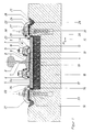
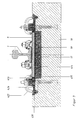
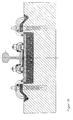
- 1 to 4 and 6 is a Rail 1 with head 2 and foot 3 with the interposition of one elastic layer 4 on a rigid plate 5 held. This is done with the help of rail tension clamps 6 and 7, with one end 8 on the Support foot 3 and the other end 9 on plate 5 and tensioned in the middle by a nut 10 will.
- This nut is on the thread of one Screwed hook screw 11, which into a rib 12 the plate 5 is suspended.
- the bearing surface 5a of the Plate 5 is slightly inclined so that the median plane the rail a small angle to the vertical forms what the transfer of shear forces to the Plate 5 and the matching of the shapes of rail and Wheel rim relieved.
- This plate 5 is in a recess 13 of a buffer 14 made of elastic material, preferably vulcanized into it.
- This buffer 14 points below the plate 5 has a base part 15, the predominantly one Shore A hardness from 55 to 65, and one around the plate 5 extending approximately vertically upward Edge part 16, which is made of a material with a Shore A hardness is from 70 to 80 and a width owns, which is significantly less than the height of the Base part 15 and smaller in the exemplary embodiments than half the height and preferably about the same is a quarter.
- the buffer has 15 in the base part Cavities 17, which is associated with the lower Shore hardness to a spring stiffness in the vertical direction of leads about 10 kN / mm. On the outside of the curve is the Number of voids reduced. The hereby achieved Increasing the rigidity reduces the lateral deflection of the rail head 2.
- a concrete part 18, in particular a threshold, has a recess 19 in the form of a recess in which the buffer 14 carrying the plate 5 is inserted is.
- the height of the recess is such that the Plate 5 completely or largely within the recess 19 lies.
- the side walls 20 of the recess 19 are slightly less than the vertical Degrees, e.g. 5 °, inclined so that it goes from top to bottom converge. This applies at least to the area of Base part.
- the plate 5 is by two plate clamps 21st and 22 loaded, the biased inner end 23 rests on the plate surface.
- a support member 24 engages with a channel-shaped extension 25 in one Channel 26 and is otherwise 27 by side ribs performed (see. Fig. 4 and 6). The support member 24 is therefore in the longitudinal and transverse directions against displacement secured.
- the second end 28 of the plate clamp 22 engages in the trough-shaped extension 25.
- the middle section 29 is through the head 30 of a screw 31 held on an elevated part 32 of the support member.
- the dashed line 16a in FIG. 2 indicates how the edge part 16 looks in the relaxed state.
- the solid line 16b shows the edge part 16 in the installation position, where the material is under tension stands.
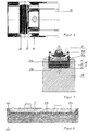
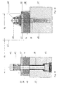
- FIG. 5 shows a modification in which for corresponding Parts used by 100 increased reference numerals will.
- the main difference is that the outer end 128 of the plate clamp 122 immediately rests in the channel 126 of the concrete part 118. Further is the support member 124 between the the side wall 120 formed level and this gutter 126, so it has a very small design.
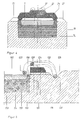
- the base part 215 consists of five layers a to e, of which layers a, c and e have a greater hardness than layers b and d and where the top layer e is integral with the Edge part 216 is formed. The rest of the parts have remained unchanged have their reference numerals maintained.
- the plate 5 acts with a buffer 314, in which the edge part 316 integral with the top layer of base 315 is trained and has a greater hardness than that lower section of base part 215.
- a buffer 314 in which the edge part 316 integral with the top layer of base 315 is trained and has a greater hardness than that lower section of base part 215.
- steel plates 335 inserted, preferably vulcanized in order the buffer 314 and thus also the rail inclination to give greater stability, which is particularly true for high-speed railways is desired.
- the steel plates can also textile inserts or the like. used will. Due to the multiple media change is nevertheless achieved high damping.
- the multilayer structure is particularly recommended with a cellular structure.
- the recess for receiving the buffer 14 can also be formed by a rectangular frame 36, on a screed or other surface 37 is attached. This can be done in the usual way four threshold screws arranged outside the frame 36 happen or according to FIGS. 12 and 13 by Screws 38 and 39, which the plate 5 "and the buffer 14 prevail, ie completely within the Plate surface.
- the screw 38 has one Head 40, on which there is a helical compression spring trained plate clamp 41 supports. Of the Screw shaft engages in one with its thread the base 37 held nut 42.
- the screw 39 has an abutment 43 on which one is formed Wire bent plate clamp 44 supports.
- the plate 5 is in the embodiments of the Vulcanized buffer material. But it is often enough also, just insert the plate.
Landscapes
- Engineering & Computer Science (AREA)
- Mechanical Engineering (AREA)
- Architecture (AREA)
- Civil Engineering (AREA)
- Structural Engineering (AREA)
- Railway Tracks (AREA)
Description
- Fig. 1
- einen Querschnitt durch ein erfindungsgemäßes Schienenlager,
- Fig. 2
- einen Schnitt durch den Puffer und eine zugehörige geringfügig abgewandelte Platte,
- Fig. 3
- eine Draufsicht auf die Teile der Fig. 2,
- Fig. 4
- einen Schnitt längs der Linie A-A in Fig. 1,
- Fig. 5
- in einer Teildarstellung entsprechend Fig. 1 eine abgewandelte Ausführungsform,
- Fig. 6
- eine Draufsicht auf den linken Teil einer Betonschwelle,
- Fig. 7
- einen Schnitt durch eine abgewandelte Ausführungsform,
- Fig. 8
- einen Querschnitt durch die Kombination aus Puffer und Platte bei einem geänderten Ausführungsbeispiel,
- Fig. 9
- einen Querschnitt durch eine weitere Ausführungsform eines erfindungsgemäßen Schienenlagers,
- Fig.10
- einen Querschnitt durch eine weitere Ausführungsform,
- Fig.11
- eine Draufsicht auf den linken Teil der Betonschwelle der Fig. 10 und
- Fig. 12 und 13
- zwei weitere Ausführungsformen der Platten-Spannklemmen.
Claims (17)
- Schienenlager mit einem Puffer (14; 114; 214; 314) aus elastischem Material, der ein Basisteil (15; 115; 215; 315) und ein eine Vertiefung (13) bildendes Randteil (16; 116; 216; 316) aufweist und in einer die Vertiefung zumindest teilweise in der Höhe überlappenden Ausnehmung (19; 119) der Unterkonstruktion angeordnet ist, und mit einer durch Platten-Spannklemmen (21, 22; 41; 44; 122) belasteten, in der Vertiefung aufgenommenen Platte (5; 5'; 5"), auf der die Schiene (1) mittels Schienen-Spannklemmen (6, 7) gehalten ist, dadurch gekennzeichnet, daß die Ausnehmung (19) ringsum geschlossene, bis zum Boden reichende Seitenwände (20) besitzt, daß zumindest die in Schienenrichtung zwischen den Seitenwänden (20, 33; 33'; 133) der Ausnehmung (19) und der Platte (5; 5') verlaufenden Abschnitte des Randteils (16; 116; 216; 316) des Puffers (14; 114; 214; 314) in ihrer Einbaustellung, in der das Basisteil (15; 115; 215; 315) unter dem Einfluß der Platten-Spannklemmen (21, 22; 41, 44; 122) in Vertikalrichtung vorgespannt ist, auch durch die Platten-Spannklemmen in Horizontalrichtung vorgespannt sind.
- Schienenlager, insbesondere nach Anspruch 1, mit einem Puffer (14; 114; 214; 314; 414) aus elastischem Material, der ein Basisteil (15; 115; 215; 315; 415) und ein eine Vertiefung (13) bildendes Randteil (16; 116; 216; 316; 416) aufweist und in einer Ausnehmung (19; 119) der Unterkonstruktion angeordnet ist, und mit einer durch Platten-Spannklemmen (21, 22; 41; 44; 122) belasteten, in der Vertiefung aufgenommenen Platte (5; 5'; 5"), auf der die Schiene mittels Schienen-Spannklemmen (6, 7) gehalten ist, dadurch gekennzeichnet, daß zumindest die in Schienenrichtung verlaufenden Abschnitte des Randteils (16; 116; 216; 316; 416) in ihrer Einbaustellung, in der das Basisteil (15; 115; 215; 315; 415) unter dem Einfluß der Platten-Spannklemmen (21, 22; 41, 44; 122) in Vertikalrichtung vorgespannt ist, auch durch die Platten-Spannklemmen in Horizontalrichtung vorgespannt sind, und daß der Puffer (14; 114; 214; 314; 414) im Randteil (16; 116; 216; 316; 416) aus einem Material größerer Härte besteht und im Basisteil (15; 115; 215; 315; 415) ein Material geringerer Härte aufweist.
- Schienenlager nach Anspruch 1 oder 2, gekennzeichnet durch von oben nach unten konvergierende Flächen an den Seitenwänden (20, 33; 33'; 133) der Ausnehmung (19) und/oder der Platte (5; 5').
- Schienenlager nach einem der Ansprüche 1 bis 3, dadurch gekennzeichnet, daß die Härte im Randteil (16; 116) etwa 70 bis 80 Shore A und im Basisteil (15; 115) etwa 55 bis 65 Shore A beträgt.
- Schienenlager nach einem der Ansprüche 1 bis 4, dadurch gekennzeichnet, daß das Basisteil (15; 315) aus mehreren Schichten unterschiedlicher Härte besteht.
- Schienenlager nach einem der Ansprüche 1 bis 5, dadurch gekennzeichnet, daß das Basisteil (15; 115; 415) Hohlräume (17) aufweist, die an der kurvenäußeren Seite in geringerem Maße vorgesehen sind.
- Schienenlager nach einem der Ansprüche 1 bis 6, dadurch gekennzeichnet, daß das Basisteil (15; 115; 215; 315; 415) eine Höhe von mindestens 25 mm besitzt.
- Schienenlager nach einem der Ansprüche 1 bis 7, dadurch gekennzeichnet, daß das Basisteil (15; 115; 215; 315; 415) eine Federsteife von 8 bis 12 kN/mm besitzt.
- Schienenlager nach einem der Ansprüche 1 bis 8, dadurch gekennzeichnet, daß die Platte (5) in die Vertiefung (13) des Puffers (14) einvulkanisiert ist.
- Schienenlager nach einem der Ansprüche 1 bis 9, dadurch gekennzeichnet, daß die Unterkonstruktion durch ein Betonteil (18) gebildet ist, in dessen Oberseite die Ausnehmung (19) als Vertiefung eingeformt ist.
- Schienenlager nach einem der Ansprüche 1 bis 10, dadurch gekennzeichnet, daß der Mittelabschnitt (29; 129) jeder Platten-Spannklemme (21, 22; 122) auf einem drehfest gehaltenen Stützelement (24; 124) ruht, das vollständig außerhalb der Ebene angeordnet ist, welche durch die zur Schiene (1) parallele Seitenwand (20; 120) der Ausnehmung (19; 119) bestimmt ist.
- Schienenlager nach Anspruch 10 und 11, dadurch gekennzeichnet, daß das Stützelement (124) zwischen der Ausnehmung (119) und einer eine direkte Abstützung der Platten-Spannklemme (122) ermöglichenden, parallel zur Schiene verlaufenden Rinne (126) angeordnet ist.
- Schienenlager nach einem der Ansprüche 10 bis 12, dadurch gekennzeichnet, daß der Beton faserverstärkt ausgeführt ist.
- Schienenlager nach einem der Ansprüche 10 bis 12, dadurch gekennzeichnet, daß das Stützelement (124) faserverstärkt ausgeführt ist.
- Schienenlager nach einem der Ansprüche 1 bis 14, dadurch gekennzeichnet, daß der Abstand (a1) der Platten-Seitenwand von der Schiene auf der kurvenäußeren Seite größer ist als der Abstand (a2) auf der kurveninneren Seite.
- Schienenlager nach einem der Ansprüche 1 bis 15, dadurch gekennzeichnet, daß die Platten-Spannklemmen (41; 44) sich an Widerlagern von Schrauben (38; 39) abstützen, deren Schäfte die Platte (5") und den Puffer (14) durchsetzen und in der Unterkonstruktion verankert sind.
- Schienenlager nach einem der Ansprüche 1 bis 16, dadurch gekennzeichnet, daß die Platten-Spannklemmen (41) Schrauben-Druckfedern sind.
Applications Claiming Priority (3)
| Application Number | Priority Date | Filing Date | Title |
|---|---|---|---|
| DE4328347 | 1993-08-24 | ||
| DE4328347A DE4328347C2 (de) | 1993-08-24 | 1993-08-24 | Schienenlager |
| PCT/EP1994/002759 WO1995006166A1 (de) | 1993-08-24 | 1994-08-19 | Schienenlager |
Publications (2)
| Publication Number | Publication Date |
|---|---|
| EP0739436A1 EP0739436A1 (de) | 1996-10-30 |
| EP0739436B1 true EP0739436B1 (de) | 1998-10-21 |
Family
ID=6495829
Family Applications (1)
| Application Number | Title | Priority Date | Filing Date |
|---|---|---|---|
| EP94926854A Expired - Lifetime EP0739436B1 (de) | 1993-08-24 | 1994-08-19 | Schienenlager |
Country Status (3)
| Country | Link |
|---|---|
| EP (1) | EP0739436B1 (de) |
| DE (2) | DE4328347C2 (de) |
| WO (1) | WO1995006166A1 (de) |
Cited By (2)
| Publication number | Priority date | Publication date | Assignee | Title |
|---|---|---|---|---|
| WO2007147581A3 (de) * | 2006-06-20 | 2008-01-24 | Edilon Sedra Gmbh | Kontinuierliche elastische schienenlagerung |
| DE102022003578A1 (de) * | 2022-09-27 | 2024-03-28 | Elisabeth Ortwein | Schienenlagerungseinrichtung zur schalldämpfenden Lagerung einer Schiene |
Families Citing this family (4)
| Publication number | Priority date | Publication date | Assignee | Title |
|---|---|---|---|---|
| DE19516097C2 (de) * | 1995-05-03 | 1999-01-28 | Draebing Kg Wegu | Schienenlagerung für eine Schiene |
| US7070934B2 (en) | 1999-01-12 | 2006-07-04 | Sangamo Biosciences, Inc. | Ligand-controlled regulation of endogenous gene expression |
| BE1013537A3 (nl) * | 2000-05-25 | 2002-03-05 | Composite Damping Material Nv | Werkwijze en strook voor het uitlijnen van een geluidsarme spoorlijn. |
| DE102023003797A1 (de) * | 2023-09-19 | 2025-03-20 | ORTEC Gesellschaft für schienentechnische Systeme mbH | Schienenlager |
Family Cites Families (7)
| Publication number | Priority date | Publication date | Assignee | Title |
|---|---|---|---|---|
| DE2032915A1 (de) * | 1970-07-02 | 1972-01-13 | Vossloh Werke GmbH, 5980 Werdohl | Schwellenlose Befestigung von Schie nen auf Tunnelsohlen, Farbahnplatten und dergleichen |
| DE2717394C3 (de) * | 1977-04-20 | 1980-10-16 | Hoesch Werke Ag, 4600 Dortmund | Höhen- und stufenlos seitenverstellbare federnde Schienenbefestigung |
| DE8615554U1 (de) * | 1986-06-10 | 1987-12-03 | Stahlwerke Peine-Salzgitter Ag, 3150 Peine | Betonschwelle |
| DE3926392A1 (de) * | 1989-02-01 | 1990-08-02 | Studiengesellschaft Fuer Unter | Schalldaemmendes schienenlager |
| DE3937086A1 (de) * | 1989-11-07 | 1991-05-08 | Clouth Gummiwerke Ag | Einrichtung zum lagern von schienen fuer schienenfahrzeuge |
| DE4031540C2 (de) * | 1990-10-05 | 1995-01-26 | Heinz Fischer | Schienenlager |
| DE4211366C2 (de) * | 1992-04-04 | 1995-05-24 | Heinz Fischer | Schienenlager |
-
1993
- 1993-08-24 DE DE4328347A patent/DE4328347C2/de not_active Expired - Fee Related
-
1994
- 1994-08-19 EP EP94926854A patent/EP0739436B1/de not_active Expired - Lifetime
- 1994-08-19 DE DE59407156T patent/DE59407156D1/de not_active Expired - Fee Related
- 1994-08-19 WO PCT/EP1994/002759 patent/WO1995006166A1/de not_active Ceased
Cited By (2)
| Publication number | Priority date | Publication date | Assignee | Title |
|---|---|---|---|---|
| WO2007147581A3 (de) * | 2006-06-20 | 2008-01-24 | Edilon Sedra Gmbh | Kontinuierliche elastische schienenlagerung |
| DE102022003578A1 (de) * | 2022-09-27 | 2024-03-28 | Elisabeth Ortwein | Schienenlagerungseinrichtung zur schalldämpfenden Lagerung einer Schiene |
Also Published As
| Publication number | Publication date |
|---|---|
| DE4328347A1 (de) | 1995-03-02 |
| WO1995006166A1 (de) | 1995-03-02 |
| DE59407156D1 (de) | 1998-11-26 |
| EP0739436A1 (de) | 1996-10-30 |
| DE4328347C2 (de) | 1997-06-26 |
Similar Documents
| Publication | Publication Date | Title |
|---|---|---|
| EP0249574B1 (de) | Betonschwellensystem | |
| AT401397B (de) | Befestigungsvorrichtung für eisenbahnschienen und befestigungsfeder | |
| EP3597825A1 (de) | Schienenbefestigungssystem | |
| EP0739436B1 (de) | Schienenlager | |
| DE102019207929A1 (de) | Schienenbefestigungssystem | |
| EP0013313A1 (de) | Eisenbahnschiene | |
| EP1866481B1 (de) | Schienenlager | |
| EP0198158B1 (de) | Elastisches Schienenlager | |
| EP1114221B1 (de) | Schwellenrahmen für eine gleisanlage für schienengebundene fahrzeuge, insbesondere für einen schotteroberbau | |
| DE3926392A1 (de) | Schalldaemmendes schienenlager | |
| EP1206599B1 (de) | Dämpfungsprofil für rillenschienen | |
| DE19924891C1 (de) | Schalldämmendes Schienenlager | |
| DE4211366C2 (de) | Schienenlager | |
| DE10237176B4 (de) | Fahrbahn für Magnetbahnzüge | |
| EP0456147B1 (de) | Gleiskörper | |
| DE19920146B4 (de) | Lagerung einer Schiene für Schienenfahrzeuge | |
| EP0948679B1 (de) | Unterbau für ein aus schienen gebildetes gleis für schienenfahrzeuge | |
| DE4031540C2 (de) | Schienenlager | |
| DE3022322A1 (de) | Profillagerstreifen aus elastomerem werkstoff fuern gleistoege | |
| DE10128844B4 (de) | Vorrichtung zum Befestigen von Schienen auf einem festen Untergrund | |
| DE3708752A1 (de) | Verstellbare schienenbefestigung | |
| EP1693516B1 (de) | Schwingungsabsorberanordnung | |
| DE1534108A1 (de) | Gleiskonstruktion | |
| DE2511685A1 (de) | Schienengleicher bahnuebergang und verfahren zu seiner herstellung | |
| DE4040785A1 (de) | Eisenbahnoberbau und betonquerschwelle |
Legal Events
| Date | Code | Title | Description |
|---|---|---|---|
| PUAI | Public reference made under article 153(3) epc to a published international application that has entered the european phase |
Free format text: ORIGINAL CODE: 0009012 |
|
| 17P | Request for examination filed |
Effective date: 19960626 |
|
| AK | Designated contracting states |
Kind code of ref document: A1 Designated state(s): DE |
|
| GRAG | Despatch of communication of intention to grant |
Free format text: ORIGINAL CODE: EPIDOS AGRA |
|
| 17Q | First examination report despatched |
Effective date: 19971104 |
|
| GRAG | Despatch of communication of intention to grant |
Free format text: ORIGINAL CODE: EPIDOS AGRA |
|
| GRAH | Despatch of communication of intention to grant a patent |
Free format text: ORIGINAL CODE: EPIDOS IGRA |
|
| GRAH | Despatch of communication of intention to grant a patent |
Free format text: ORIGINAL CODE: EPIDOS IGRA |
|
| GRAA | (expected) grant |
Free format text: ORIGINAL CODE: 0009210 |
|
| AK | Designated contracting states |
Kind code of ref document: B1 Designated state(s): DE |
|
| REF | Corresponds to: |
Ref document number: 59407156 Country of ref document: DE Date of ref document: 19981126 |
|
| PLBE | No opposition filed within time limit |
Free format text: ORIGINAL CODE: 0009261 |
|
| STAA | Information on the status of an ep patent application or granted ep patent |
Free format text: STATUS: NO OPPOSITION FILED WITHIN TIME LIMIT |
|
| 26N | No opposition filed | ||
| PGFP | Annual fee paid to national office [announced via postgrant information from national office to epo] |
Ref country code: DE Payment date: 20010816 Year of fee payment: 8 |
|
| PG25 | Lapsed in a contracting state [announced via postgrant information from national office to epo] |
Ref country code: DE Free format text: LAPSE BECAUSE OF NON-PAYMENT OF DUE FEES Effective date: 20030301 |