EP0491118B2 - Reflexions-Lichttaster - Google Patents
Reflexions-Lichttaster Download PDFInfo
- Publication number
- EP0491118B2 EP0491118B2 EP91115348A EP91115348A EP0491118B2 EP 0491118 B2 EP0491118 B2 EP 0491118B2 EP 91115348 A EP91115348 A EP 91115348A EP 91115348 A EP91115348 A EP 91115348A EP 0491118 B2 EP0491118 B2 EP 0491118B2
- Authority
- EP
- European Patent Office
- Prior art keywords
- light
- sensor according
- reflected light
- light sensor
- sensitive elements
- Prior art date
- Legal status (The legal status is an assumption and is not a legal conclusion. Google has not performed a legal analysis and makes no representation as to the accuracy of the status listed.)
- Expired - Lifetime
Links
- 230000003321 amplification Effects 0.000 claims description 8
- 238000003199 nucleic acid amplification method Methods 0.000 claims description 8
- 230000003287 optical effect Effects 0.000 claims description 6
- 238000006243 chemical reaction Methods 0.000 claims description 3
- 238000011156 evaluation Methods 0.000 description 6
- 230000005540 biological transmission Effects 0.000 description 2
- 238000010586 diagram Methods 0.000 description 2
- 230000005693 optoelectronics Effects 0.000 description 2
- 238000001514 detection method Methods 0.000 description 1
- 230000000694 effects Effects 0.000 description 1
- 238000009429 electrical wiring Methods 0.000 description 1
- 238000001914 filtration Methods 0.000 description 1
- 230000005855 radiation Effects 0.000 description 1
- 239000000523 sample Substances 0.000 description 1
Images



Classifications
-
- G—PHYSICS
- G01—MEASURING; TESTING
- G01S—RADIO DIRECTION-FINDING; RADIO NAVIGATION; DETERMINING DISTANCE OR VELOCITY BY USE OF RADIO WAVES; LOCATING OR PRESENCE-DETECTING BY USE OF THE REFLECTION OR RERADIATION OF RADIO WAVES; ANALOGOUS ARRANGEMENTS USING OTHER WAVES
- G01S17/00—Systems using the reflection or reradiation of electromagnetic waves other than radio waves, e.g. lidar systems
- G01S17/87—Combinations of systems using electromagnetic waves other than radio waves
-
- G—PHYSICS
- G01—MEASURING; TESTING
- G01S—RADIO DIRECTION-FINDING; RADIO NAVIGATION; DETERMINING DISTANCE OR VELOCITY BY USE OF RADIO WAVES; LOCATING OR PRESENCE-DETECTING BY USE OF THE REFLECTION OR RERADIATION OF RADIO WAVES; ANALOGOUS ARRANGEMENTS USING OTHER WAVES
- G01S17/00—Systems using the reflection or reradiation of electromagnetic waves other than radio waves, e.g. lidar systems
- G01S17/02—Systems using the reflection of electromagnetic waves other than radio waves
- G01S17/04—Systems determining the presence of a target
-
- G—PHYSICS
- G01—MEASURING; TESTING
- G01S—RADIO DIRECTION-FINDING; RADIO NAVIGATION; DETERMINING DISTANCE OR VELOCITY BY USE OF RADIO WAVES; LOCATING OR PRESENCE-DETECTING BY USE OF THE REFLECTION OR RERADIATION OF RADIO WAVES; ANALOGOUS ARRANGEMENTS USING OTHER WAVES
- G01S7/00—Details of systems according to groups G01S13/00, G01S15/00, G01S17/00
- G01S7/48—Details of systems according to groups G01S13/00, G01S15/00, G01S17/00 of systems according to group G01S17/00
- G01S7/481—Constructional features, e.g. arrangements of optical elements
- G01S7/4814—Constructional features, e.g. arrangements of optical elements of transmitters alone
Definitions
- the invention relates to a reflection light sensor according to the preamble of Claim 1.
- Such a light sensor is known from DE-PS 35 13 671.
- a rotatably mounted deflection mirror is arranged in such a way that by pivoting the deflecting mirror e.g. the focus position of the received light beam across the optical axis on the photoelectric transducer array is movable.
- the photoelectric converter arrangement is made of two photoelectric elements, the output signals of a differential amplifier act so that at the output of the differential amplifier one of the Difference in radiation power on the two photoelectric elements corresponding signal is present.
- a reflection light scanner known from DE-PS 29 24 685 are for Change the angle specifying the remote switching point between the optical axes of the transmitting and receiving optics both the light source and also the light receiver with the associated optics, each in a swivel bracket housed.
- the brackets are made using a spindle drive pivoted, which changes the angle at which the axes of the Cut optics.
- the object of the invention is to a light scanner of the type mentioned create in which all optical and optoelectric components as well as the all electronics can be arranged firmly and immovably in the housing, without the defined setting of a certain remote switching point must be dispensed with.
- the detection of tactile objects is in front of, within and possible behind a defined scanning area, whereby an object corresponds to the corresponding Distance value can be assigned.
- a light sensor can also be implemented, which has any number of remote switching points with regard to the distance. This is achieved through continuous current control of the various Light centers of the light source and / or continuous evaluation variation of the light-sensitive elements of the light receiver.
- the continuous control can e.g. by means of a sawtooth course happen, regardless of the distance value always the far switching point is traversed and the corresponding associated amplitude value of sawtooth-shaped control corresponds to the current distance value of the touch object. This is the realization of a distance sensor with extremely simple means possible.
- the reflection light scanner according to the invention consists of the Light source 1 with the two light centers 1 'and 1 "and from the light receiver 2 with the two photosensitive elements 2 'and 2 ".
- the two Light centers 1 'and 1 " are on the surface by means of common transmission optics 5 of the touch object 10 or 10 'shown, for reasons of simplification in Figure 1 only the two central beams 11 'and 11 "of the transmitted light beam are shown.
- the central beam 12 on the receiving side is shown which is effective when either the touch object 10 is at maximum sensing range A and only the light center 1 'is controlled or the touch object 10' is in the position minimum scanning distance A 'and only the light center 1 "is active.
- the distance between the two central beams 11 'and 11 "on the touch object 10 corresponds to the length dimension in the X direction at maximum scanning distance A. L.
- the photo currents of the two photosensitive elements 2 'and 2 "of the light receiver 2 are separated after current / voltage conversion 21 ', 21 "and Preamplification 22 ', 22 “of the two electrical channels of a differential amplifier 23 supplied (see also Figure 2).
- the output signal of the differential amplifier acts on an evaluation circuit 27 that this signal evaluated in terms of amplitude and sign.
- this signal e.g. positive and it reaches one in the evaluation circuit 27 predefined response threshold, this means "touch object is located between remote switching point and light button ", ie within the sensing range. In contrast, for smaller signals than the response threshold "touch object is located at greater distances than the far switching point ", ie outside the Sensing range.
- the electronics of the reflected light sensor has the following basic structure.
- the intensity of the light centers 1 ', 1 " can be inversely controlled via the control voltage U St, LED applied to the control line 29, and the current amplitude i', i" can be controlled via the two voltage followers 18 ', 18 "by varying the gain of the LED drivers 20 ', 20 “can be set continuously (see also FIG. 3).
- the transmit pulse oscillator 19 determines the current pulse width and the repetition frequency for the current control of the light centers 1 ', 1 "of the light source 1.
- the photosensitive elements 2 ', 2 "of the light receiver 2 and the current / voltage conversion 21', 21" are outlined on the receiving side.
- the downstream preamplifiers 22 ', 22 "with frequency-selective behavior can be adjusted in their amplification by means of the control voltages U St , W1 or U St , W2 (control lines 28', 28").
- a different evaluation of the photosensitive elements 2 ', 2 " is possible by means of U St, W1 or U St, W2 .
- the output signals of the preamplifiers 22 ', 22 act on the inputs of the differential amplifier 23, which in turn with its output signal on the Input of the threshold amplifier 24 acts.
- the binary signal is the output driver 26 supplied, which depending on the object position of the touch object 10 or 10 ' Output activated or not activated.
- FIG. 3 again shows the relationship between the transmission currents i ', i "of the light centers 1', 1" as a function of the control voltage U St , LED .
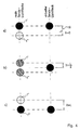
- the virtual migrates Spots of light from top to bottom (see Figure 4).
Landscapes
- Physics & Mathematics (AREA)
- Electromagnetism (AREA)
- Engineering & Computer Science (AREA)
- Computer Networks & Wireless Communication (AREA)
- General Physics & Mathematics (AREA)
- Radar, Positioning & Navigation (AREA)
- Remote Sensing (AREA)
- Electronic Switches (AREA)
- Length Measuring Devices By Optical Means (AREA)
- Geophysics And Detection Of Objects (AREA)
- Measurement Of Optical Distance (AREA)
Description
- Tastobjekt befindet sich zwischen dem bezüglich der kürzeren Distanz fernen Schaltpunkt und Lichttaster (Fall 1),
- Tastobjekt befindet sich zwischen dem bezüglich der größeren Distanz fernen Schaltpunkt und Lichttaster (Fall 1'),
- Tastobjekt befindet sich bei größeren Distanzen als der größere ferne Schaltpunkt (Fall 2).
- Figur 1:
- Prinzipskizze mit den Zentralstrahlen zweier Sendelichtbündel sowie den Zentralstrahl des Empfangslichtbündels und ein Tastobjekt in zwei unterschiedlichen Positionen auf der Z-Achse.
- Figur 2:
- Blockschaltbild des erfindungsgemäßen Reflexionslichttasters,
- Figur 3:
- Die beiden Lichtzentren beaufschlagenden Stromamplituden als Funktion der Steuerspannung USt, LED zur elektronischen Einstellung des fernen Schaltpunktes.
- Figur 4:
- Schematische Darstellung sowohl der realen Sendelichtflecke als
auch der virtuellen Sendelichtflecke auf dem Tastobjekt für drei
verschiedene Steuerspannungen USt, LED nach Figur 3 und zwar
- Figur 4 a) mit USt, LED = 0 V,
- Figur 4 b) mit USt, LED = 2,5 V,
- Figur 4 c) mit USt, LED = 5 V,
- Figur 5:
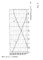
- Ein beispielhafter funktionaler Zusammenhang zwischen dem Einstellbereich B in mm und der Steuerspannung USt, LED in Volt für den Reflexionsfaktor RK = 0,03 bis RK = 1.
Auf der Empfangsseite sind die lichtempfindlichen Elemente 2', 2" des Lichtempfängers 2 sowie die Strom-/Spannungskonversion 21', 21" skizziert. Die nachgeschalteten Vorverstärker 22', 22" mit frequenzselektivem Verhalten sind mittels der Steuerspannungen USt, W1 bzw. USt, W2 (Steuerleitungen 28', 28") in ihrer Verstärkung einstellbar. Mittels USt, W1 bzw. USt, W2 ist eine unterschiedliche Bewertung der lichtempfindlichen Elemente 2', 2" möglich.
Claims (11)
- Reflexionslichttaster, bei dem Lichtsender und Lichtempfänger mit jeweils vorgeordneter Sende- und Empfangsfrontlinse benachbart zueinander angeordnet sind und der mit einer Einrichtung zum Einstellen des Grenzabstands eines Tastobjekts vom Tastergehäuse versehen ist, die lichtempfangsseitig zwei lichtempfindliche Elemente aufweist, deren Ausgangssignale einen Differenzverstärker beaufschlagen, dessen Ausgangssignal in einer Auswerteschaltung bezüglich Amplitude und Vorzeichen bewertet wird, wobei sich das Tastobjekt im Grenzabstand befindet, wenn die Amplitude des Ausgangssignals des Differenzverstärkers einer in der Auswerteschaltung vorgegebenen Ansprechschwelle entspricht, dadurch gekennzeichnet, dass der Lichtsender (1) wenigstens zwei voneinander unabhängige Lichtquellen (1', 1") enthält, der Lichtempfänger wenigstens zwei getrennt auswertbare lichtempfindliche Elemente (2', 2") aufweist und der jeweilige Grenzabstand innerhalb einer definierten Tastzone durch unterschiedliche Verstärkung der Ausgangssignale der lichtempfindlichen Elemente (2', 2") stufenlos einstellbar ist.
- Reflexionslichttaster nach Anspruch 1, gekennzeichnet durch eine kombinierte Einstellung des Grenzabstands mittels inverser Steuerung der Ströme der Lichtquellen (1', 1") und unterschiedlicher Verstärkung der Ausgangssignale der lichtempfindlichen Elemente (2', 2").
- Reflexionslichttaster nach den Ansprüchen 1 oder 2, dadurch gekennzeichnet, dass Lichtsender (1) und Lichtempfänger (2) jeweils eine frei wählbare Anzahl voneinander unabhängiger Lichtquellen (1' - 1N) und voneinander getrennter lichtempfindlicher Elemente (2' bis 2M) enthalten.
- Reflexionslichttaster nach den Ansprüchen 2 oder 3, dadurch gekennzeichnet, dass die verschiedenen Lichtquellen (1' bis 1N) strommäßig kontinuierlich steuerbar sind.
- Reflexionslichttaster nach den Ansprüchen 1 - 4, dadurch gekennzeichnet, dass die unterschiedliche Verstärkung der Ausgangssignale der lichtempfindlichen Elemente (2' bis 2M) kontinuierlich variierbar ist.
- Reflexionslichttaster nach Anspruch 4, dadurch gekennzeichnet, dass die Steuerung der Ströme der Lichtquellen (1' bis 1N) mittels einer an der Steuerleitung (29) liegenden Steuerspannung mit sägezahnförmigem Verlauf erfolgt.
- Reflexionslichttaster nach Anspruch 5, dadurch gekennzeichnet, dass die Fotoströme der lichtempfindlichen Elemente (2' bis 2M) des Lichtempfängers (2) nach Strom / Spannungskonversion (21', 21") und getrennter Vorverstärkung (22', 22") einem Differenzverstärker (23) zugeführt werden, dessen Ausgangssignal eine Auswerteschaltung (27) beaufschlagt, die dieses Signal nach Amplitude und Vorzeichen bewertet.
- Reflexionslichttaster nach Anspruch 7, dadurch gekennzeichnet, dass die Vorverstärker (22', 22") frequenzselektives Verhalten aufweisen und mittels Steuerspannungen USt, W1 und USt, W2 über Steuerleitungen (28', 28") in ihrer Verstärkung einstellbar sind.
- Reflexionslichttaster nach Anspruch 4, dadurch gekennzeichnet, dass die Stromamplitude des Lichtsenders (1) über Spannungsfolger (18', 18") durch Verstärkungsvariation von Treiberstufen (20', 20") stufenlos einstellbar ist.
- Reflexionslichttaster nach den Ansprüchen 1 bis 9, dadurch gekennzeichnet, dass die Tastzone durch wenigstens zwei unabhängig einstellbare unterschiedliche Schaltpunkte definiert ist.
- Reflexionslichttaster nach den Ansprüchen 1 - 10, dadurch gekennzeichnet, dass die im Tastergehäuse installierten optischen, optoelektronischen und elektronischen Bauteile unverrückbar im Tastergehäuse (7) befestigt sind.
Applications Claiming Priority (2)
| Application Number | Priority Date | Filing Date | Title |
|---|---|---|---|
| DE4040225 | 1990-12-15 | ||
| DE4040225A DE4040225C2 (de) | 1990-12-15 | 1990-12-15 | Reflexions-Lichttaster |
Publications (4)
| Publication Number | Publication Date |
|---|---|
| EP0491118A2 EP0491118A2 (de) | 1992-06-24 |
| EP0491118A3 EP0491118A3 (en) | 1992-10-07 |
| EP0491118B1 EP0491118B1 (de) | 1995-08-30 |
| EP0491118B2 true EP0491118B2 (de) | 2001-05-16 |
Family
ID=6420488
Family Applications (1)
| Application Number | Title | Priority Date | Filing Date |
|---|---|---|---|
| EP91115348A Expired - Lifetime EP0491118B2 (de) | 1990-12-15 | 1991-09-11 | Reflexions-Lichttaster |
Country Status (3)
| Country | Link |
|---|---|
| US (1) | US5225689A (de) |
| EP (1) | EP0491118B2 (de) |
| DE (2) | DE4040225C2 (de) |
Families Citing this family (55)
| Publication number | Priority date | Publication date | Assignee | Title |
|---|---|---|---|---|
| DE4140614C2 (de) * | 1990-12-15 | 1994-03-10 | Leuze Electronic Gmbh & Co | Reflexionslichttaster |
| IT1255011B (it) * | 1992-03-27 | 1995-10-13 | Minnesota Mining & Mfg | Metodo e dispositivo per determinare condizioni di pienezza in un magazzino ricevente di un dispositivo per trattare un film |
| US5406073A (en) * | 1993-01-25 | 1995-04-11 | Phoenix Controls Corporation | System for detecting a movable entity within a selected space |
| DE4311691C2 (de) * | 1993-04-08 | 1996-07-04 | Sick Erwin Gmbh | Verfahren zum Justieren eines Lichtabstandstasters und Lichtabstandstaster |
| DE4312186C2 (de) * | 1993-04-14 | 1995-04-06 | Sick Optik Elektronik Erwin | Verfahren und Vorrichtungen zur Feststellung von in einem Überwachungsbereich vorhandenen Gegenständen und/oder zur Feststellung deren Position |
| US5508510A (en) * | 1993-11-23 | 1996-04-16 | Coyne & Delany Co. | Pulsed infrared sensor to detect the presence of a person or object whereupon a solenoid is activated to regulate fluid flow |
| DE4419032A1 (de) * | 1994-05-31 | 1996-01-25 | Sick Optik Elektronik Erwin | Lichttaster mit Hintergrundausblendung, realisiert nach dem Quotientenverfahren |
| DE4445535A1 (de) * | 1994-12-20 | 1996-06-27 | Tr Elektronic Gmbh | Optischer Sensor zur berührungslosen Abstandserfassung |
| US5670778A (en) * | 1995-08-31 | 1997-09-23 | Kardex Systems, Inc. | Presence detector for mobile storage systems |
| US5808296A (en) * | 1996-03-22 | 1998-09-15 | Banner Engineering Corporation | Programmable detection sensor with means to automatically adjust sensor operating characteristics to optimize performance for both high gain and low contrast applications |
| PL330188A1 (en) * | 1996-05-29 | 1999-04-26 | Deutsche Telekom Ag | Information entering apparatus |
| DE19644791C2 (de) * | 1996-10-28 | 2002-11-28 | Sick Ag | Verfahren und Vorrichtung zur Bestimmung der Lichtlaufzeit über eine zwischen einer Meßvorrichtung und einem reflektierenden Objekt angeordnete Meßstrecke |
| DE19718390A1 (de) † | 1997-04-30 | 1998-11-05 | Sick Ag | Opto-elektronischer Sensor |
| DE19721105C5 (de) * | 1997-05-20 | 2008-07-10 | Sick Ag | Opto-eletronischer Sensor |
| DE19808215C2 (de) * | 1998-02-27 | 2001-03-15 | Leuze Electronic Gmbh & Co | Optoelektronische Vorrichtung und Verfahren zu deren Betrieb |
| DE19907546C2 (de) * | 1998-03-27 | 2003-02-27 | Leuze Electronic Gmbh & Co | Optoelektronische Vorrichtung |
| DE19831493C2 (de) * | 1998-07-14 | 2002-03-14 | Leuze Electronic Gmbh & Co | Optoelektronischer Sensor |
| DE19839305B4 (de) * | 1998-08-28 | 2009-01-15 | Siemens Ag | Reflexlichtschranke |
| DE10001017B4 (de) * | 1999-01-13 | 2004-02-26 | Ifm Electronic Gmbh | Optoelektronischer Sensor, insbesondere Reflexlichttaster |
| CH695028A5 (de) * | 1999-12-24 | 2005-11-15 | Hera Rotterdam Bv | Optoelektronischer Distanzsensor und Verfahren zur optoelektronischen Distanzmessung. |
| DE10011046A1 (de) * | 2000-03-07 | 2001-10-04 | Omron Electronics Mfg Of Germa | Verfahren zum Erfassen von Abständen von Objekten mittels eines Triangulations-Sensors und Triangulations-Sensor zum Durchführen des Verfahrens |
| DE10024156A1 (de) * | 2000-05-19 | 2001-11-29 | Gerd Reime | Verfahren und Vorrichtung zur optoelektronischen Positionsbestimmung eines Gegenstands |
| US6906316B2 (en) * | 2000-10-27 | 2005-06-14 | Fuji Electric Co., Ltd. | Semiconductor device module |
| TW513558B (en) * | 2000-10-27 | 2002-12-11 | Fuji Electric Co Ltd | Range finder for automatic focusing |
| DE10106998C2 (de) * | 2000-11-04 | 2003-01-23 | Stefan Reich | Verfahren und Vorrichtung zur optischen Objekterfassung |
| ITBO20000691A1 (it) * | 2000-11-24 | 2002-05-24 | Ind Elettroniche Sensor Spa | Metodo e dispositivo per la rilevazione di un oggetto con soppressione di sfondo |
| ITBO20010114A1 (it) * | 2001-03-02 | 2002-09-02 | Datasensor Spa | Dispositivo misuratore di distanza optoelettronico |
| WO2003001245A1 (en) * | 2001-06-21 | 2003-01-03 | Tri-Tronics Company, Inc. | Adjusting the performance characteristics of a photoelectric sensor |
| DE10138609B4 (de) | 2001-08-07 | 2005-02-17 | Sick Ag | Überwachungsverfahren und optoelektronischer Sensor |
| US6764158B2 (en) * | 2001-10-02 | 2004-07-20 | Hewlett-Packard Development Company, L.P. | Compact optical sensing system |
| CA2466359A1 (en) * | 2001-11-08 | 2003-05-15 | Siemens Aktiengesellschaft | Distance measuring laser light grid |
| DE10162723A1 (de) * | 2001-12-19 | 2003-07-10 | Fachhochschule Hannover | Verfahren und Vorrichtung zur Erfassung von Objekten |
| EP1380811B2 (de) | 2002-07-03 | 2013-08-07 | Optosys SA | Optische Abstandsmessvorrichtung |
| US6894270B2 (en) * | 2002-11-01 | 2005-05-17 | Delta Faucet Canada | Sensor for washroom device with a non-circular sensing zone |
| DE10352274B4 (de) * | 2002-11-11 | 2009-02-26 | Leuze Electronic Gmbh & Co Kg | Verfahren zur Erfassung von Objektstrukturen mittels eines optischen Sensors |
| GB0311177D0 (en) * | 2003-05-15 | 2003-06-18 | Qinetiq Ltd | Non contact human-computer interface |
| EP1528411B1 (de) * | 2003-10-27 | 2010-01-27 | Bea S.A. | Entfernungsmessgerät |
| EP1693544B1 (de) * | 2005-01-21 | 2016-03-23 | Bea S.A. | Sensor für automatischen Türen |
| CH697495B1 (de) * | 2005-04-01 | 2008-11-14 | Baumer Electric Ag | Optischer Sensor und Verfahren zur Unterdrückung von Streulichtfehlern. |
| JP4785044B2 (ja) * | 2006-01-13 | 2011-10-05 | スタンレー電気株式会社 | 反射型光学センサ及び測定面の表面粗さ検出方法 |
| DE102007009244A1 (de) | 2007-02-22 | 2008-08-28 | Sick Ag | Verfahren zur Überprüfung der Funktionsweise und/oder Justierung einer optoelektronischen Sensoranordnung und optoelektronische Sensoranordnung |
| US20100096535A1 (en) * | 2008-10-19 | 2010-04-22 | Nanomotion Ltd. | Position sensor |
| US8146702B2 (en) * | 2009-09-10 | 2012-04-03 | Jervis B. Webb Company | Load handling bumper for material handling device |
| US8698333B2 (en) * | 2009-09-23 | 2014-04-15 | Zurn Industries, Llc | Flush valve hydrogenerator |
| EP2434311B1 (de) | 2010-09-27 | 2014-07-16 | Sick Ag | Verfahren zur optischen Überwachung eines Überwachungsbereiches und Reflexions-Lichttaster |
| JP5300910B2 (ja) * | 2011-04-22 | 2013-09-25 | キヤノン株式会社 | シート搬送装置、画像形成装置及び画像読取装置 |
| JP2014182028A (ja) * | 2013-03-19 | 2014-09-29 | Omron Corp | 限定領域反射型光電センサ |
| US12404714B2 (en) | 2015-09-14 | 2025-09-02 | Rytec Corporation | System and method for safety management in roll-up doors |
| US10619397B2 (en) * | 2015-09-14 | 2020-04-14 | Rytec Corporation | System and method for safety management in roll-up doors |
| ITUB20154101A1 (it) * | 2015-10-01 | 2017-04-01 | Datalogic IP Tech Srl | Sensore optoelettronico e metodo di elaborazione di un segnale elettrico |
| FR3048803B1 (fr) * | 2016-03-10 | 2018-04-06 | Antalios | Procede de determination automatique d'un niveau de remplissage d'un sac plastique et boitier pour la mise en œuvre d'un tel procede |
| DE102017129185A1 (de) | 2016-12-19 | 2018-06-21 | Wimtec Sanitärprodukte Gmbh | Verfahren zum energieeffizienten Betrieb einer Schaltungsanordnung mit einem Annäherungssensor sowie Annäherungssensoren und Schaltungsanordnungen zum Durchführen dieses Verfahrens |
| JP6914484B2 (ja) * | 2018-03-14 | 2021-08-04 | オムロン株式会社 | 光電センサ及びセンサシステム |
| MX2021007451A (es) | 2018-12-21 | 2021-09-21 | Rytec Corp | Metodo y sistema de seguridad para puertas aereas enrollables. |
| CN111366941B (zh) * | 2020-04-20 | 2025-01-28 | 奥比中光科技集团股份有限公司 | 一种tof深度测量装置及方法 |
Family Cites Families (8)
| Publication number | Priority date | Publication date | Assignee | Title |
|---|---|---|---|---|
| JPS5931814B2 (ja) * | 1978-06-19 | 1984-08-04 | オムロン株式会社 | 反射形光電スイッチ |
| JPS60256076A (ja) * | 1984-06-01 | 1985-12-17 | Nissan Motor Co Ltd | 先行車検出装置 |
| US4659922A (en) * | 1985-02-19 | 1987-04-21 | Eaton Corporation | Optical sensor device for detecting the presence of an object |
| DE3513671C3 (de) * | 1985-04-16 | 1995-03-23 | Sick Optik Elektronik Erwin | Lichttaster |
| DE3621961A1 (de) * | 1986-07-01 | 1988-01-14 | Wenglorz Sensoric Gmbh | Reflexlichtschranke zur beruehrungslosen nachfuehrung eines geraetes |
| DE3627972A1 (de) * | 1986-08-18 | 1988-02-25 | Ifm Int Fluggeraete Motoren | Photoelektrischer taster |
| DE3729334A1 (de) * | 1987-09-02 | 1989-03-16 | Sick Optik Elektronik Erwin | Lichttaster |
| US4903009A (en) * | 1988-05-18 | 1990-02-20 | Eastman Kodak Company | Intrusion detection device |
-
1990
- 1990-12-15 DE DE4040225A patent/DE4040225C2/de not_active Expired - Fee Related
-
1991
- 1991-09-11 DE DE59106373T patent/DE59106373D1/de not_active Expired - Fee Related
- 1991-09-11 EP EP91115348A patent/EP0491118B2/de not_active Expired - Lifetime
- 1991-12-13 US US07/806,243 patent/US5225689A/en not_active Expired - Lifetime
Also Published As
| Publication number | Publication date |
|---|---|
| DE4040225C2 (de) | 1994-01-05 |
| EP0491118A3 (en) | 1992-10-07 |
| EP0491118A2 (de) | 1992-06-24 |
| US5225689A (en) | 1993-07-06 |
| DE59106373D1 (de) | 1995-10-05 |
| EP0491118B1 (de) | 1995-08-30 |
| DE4040225A1 (de) | 1992-06-25 |
Similar Documents
| Publication | Publication Date | Title |
|---|---|---|
| EP0491118B1 (de) | Reflexions-Lichttaster | |
| DE10138609B4 (de) | Überwachungsverfahren und optoelektronischer Sensor | |
| DE3050124C2 (de) | Optischer Rauchmelder | |
| DE10231178B4 (de) | Optoelektronischer Sensor | |
| EP1395853A1 (de) | Vorrichtung zur optischen distanzmessung | |
| EP4310443B1 (de) | Optischer triangulationstaster | |
| DE10001017B4 (de) | Optoelektronischer Sensor, insbesondere Reflexlichttaster | |
| DE10061649A1 (de) | Optoelektronischer Distanzsensor und Verfahren zur optoelektronischen Distanzmessung | |
| EP0383352A1 (de) | Leitsensor für automatisch gelenktes Fahrzeug | |
| EP0974822B1 (de) | Drehmomentsensor und Verfahren zum Erzeugen eines drehmomentabhängigen Signals | |
| DE3013967C2 (de) | Justieranordnung für Lichtgitter | |
| DE4102152A1 (de) | Optoelektronischer sensor | |
| DE4140614A1 (de) | Reflexionslichttaster | |
| DE20118145U1 (de) | Optischer Sensor | |
| DE19619308A1 (de) | Kombinations-Lichttaster | |
| DE102016101269A1 (de) | Optoelektronischer Multifunktionssensor und Verfahren zu seinem Betrieb | |
| EP0391883A2 (de) | Optoelektronischer Hindernisdetektor | |
| EP4465079B1 (de) | Optischer distanzsensor | |
| EP3492951B1 (de) | Optoelektronische vorrichtung | |
| DE4204013A1 (de) | Reflexionslichttaster | |
| DE10253511B4 (de) | Optoelektronische Vorrichtung | |
| DE29924961U1 (de) | Optischer Sensor | |
| EP3910373B1 (de) | Auslesen von lawinenphotodiodenelementen im geigermodus | |
| DE10359561A1 (de) | Bedienelement für ein Haushaltsgerät | |
| DE202006006482U1 (de) | Optischer Sensor |
Legal Events
| Date | Code | Title | Description |
|---|---|---|---|
| PUAI | Public reference made under article 153(3) epc to a published international application that has entered the european phase |
Free format text: ORIGINAL CODE: 0009012 |
|
| 17P | Request for examination filed |
Effective date: 19910911 |
|
| AK | Designated contracting states |
Kind code of ref document: A2 Designated state(s): CH DE FR GB IT LI NL |
|
| PUAL | Search report despatched |
Free format text: ORIGINAL CODE: 0009013 |
|
| AK | Designated contracting states |
Kind code of ref document: A3 Designated state(s): CH DE FR GB IT LI NL |
|
| 17Q | First examination report despatched |
Effective date: 19940718 |
|
| GRAA | (expected) grant |
Free format text: ORIGINAL CODE: 0009210 |
|
| AK | Designated contracting states |
Kind code of ref document: B1 Designated state(s): CH DE FR GB IT LI NL |
|
| GBT | Gb: translation of ep patent filed (gb section 77(6)(a)/1977) |
Effective date: 19950829 |
|
| REF | Corresponds to: |
Ref document number: 59106373 Country of ref document: DE Date of ref document: 19951005 |
|
| ET | Fr: translation filed | ||
| ITF | It: translation for a ep patent filed | ||
| PLBQ | Unpublished change to opponent data |
Free format text: ORIGINAL CODE: EPIDOS OPPO |
|
| PLBI | Opposition filed |
Free format text: ORIGINAL CODE: 0009260 |
|
| PLBF | Reply of patent proprietor to notice(s) of opposition |
Free format text: ORIGINAL CODE: EPIDOS OBSO |
|
| 26 | Opposition filed |
Opponent name: I F M ELECTRONIC GMBH Effective date: 19960530 |
|
| NLR1 | Nl: opposition has been filed with the epo |
Opponent name: I F M ELECTRONIC GMBH |
|
| PLBF | Reply of patent proprietor to notice(s) of opposition |
Free format text: ORIGINAL CODE: EPIDOS OBSO |
|
| RDAH | Patent revoked |
Free format text: ORIGINAL CODE: EPIDOS REVO |
|
| APAC | Appeal dossier modified |
Free format text: ORIGINAL CODE: EPIDOS NOAPO |
|
| APAE | Appeal reference modified |
Free format text: ORIGINAL CODE: EPIDOS REFNO |
|
| APAC | Appeal dossier modified |
Free format text: ORIGINAL CODE: EPIDOS NOAPO |
|
| APAC | Appeal dossier modified |
Free format text: ORIGINAL CODE: EPIDOS NOAPO |
|
| PLAW | Interlocutory decision in opposition |
Free format text: ORIGINAL CODE: EPIDOS IDOP |
|
| PUAH | Patent maintained in amended form |
Free format text: ORIGINAL CODE: 0009272 |
|
| STAA | Information on the status of an ep patent application or granted ep patent |
Free format text: STATUS: PATENT MAINTAINED AS AMENDED |
|
| 27A | Patent maintained in amended form |
Effective date: 20010516 |
|
| AK | Designated contracting states |
Kind code of ref document: B2 Designated state(s): CH DE FR GB IT LI NL |
|
| GBTA | Gb: translation of amended ep patent filed (gb section 77(6)(b)/1977) | ||
| REG | Reference to a national code |
Ref country code: CH Ref legal event code: AEN Free format text: AUFRECHTERHALTUNG DES PATENTES IN GEAENDERTER FORM * AUFRECHTERHALTUNG DES PATENTES IN GEAENDERTER FORM |
|
| NLR2 | Nl: decision of opposition | ||
| ET3 | Fr: translation filed ** decision concerning opposition | ||
| ITF | It: translation for a ep patent filed | ||
| NLR3 | Nl: receipt of modified translations in the netherlands language after an opposition procedure | ||
| REG | Reference to a national code |
Ref country code: GB Ref legal event code: IF02 |
|
| APAH | Appeal reference modified |
Free format text: ORIGINAL CODE: EPIDOSCREFNO |
|
| PGFP | Annual fee paid to national office [announced via postgrant information from national office to epo] |
Ref country code: DE Payment date: 20051005 Year of fee payment: 15 |
|
| REG | Reference to a national code |
Ref country code: FR Ref legal event code: CD Ref country code: FR Ref legal event code: CJ |
|
| PGFP | Annual fee paid to national office [announced via postgrant information from national office to epo] |
Ref country code: FR Payment date: 20060727 Year of fee payment: 16 |
|
| PGFP | Annual fee paid to national office [announced via postgrant information from national office to epo] |
Ref country code: NL Payment date: 20060731 Year of fee payment: 16 |
|
| PGFP | Annual fee paid to national office [announced via postgrant information from national office to epo] |
Ref country code: CH Payment date: 20060831 Year of fee payment: 16 |
|
| PGFP | Annual fee paid to national office [announced via postgrant information from national office to epo] |
Ref country code: GB Payment date: 20060907 Year of fee payment: 16 |
|
| PGFP | Annual fee paid to national office [announced via postgrant information from national office to epo] |
Ref country code: IT Payment date: 20060930 Year of fee payment: 16 |
|
| PG25 | Lapsed in a contracting state [announced via postgrant information from national office to epo] |
Ref country code: DE Free format text: LAPSE BECAUSE OF NON-PAYMENT OF DUE FEES Effective date: 20070403 |
|
| REG | Reference to a national code |
Ref country code: CH Ref legal event code: PL |
|
| GBPC | Gb: european patent ceased through non-payment of renewal fee |
Effective date: 20070911 |
|
| PG25 | Lapsed in a contracting state [announced via postgrant information from national office to epo] |
Ref country code: NL Free format text: LAPSE BECAUSE OF NON-PAYMENT OF DUE FEES Effective date: 20080401 |
|
| NLV4 | Nl: lapsed or anulled due to non-payment of the annual fee |
Effective date: 20080401 |
|
| PG25 | Lapsed in a contracting state [announced via postgrant information from national office to epo] |
Ref country code: LI Free format text: LAPSE BECAUSE OF NON-PAYMENT OF DUE FEES Effective date: 20070930 Ref country code: CH Free format text: LAPSE BECAUSE OF NON-PAYMENT OF DUE FEES Effective date: 20070930 |
|
| REG | Reference to a national code |
Ref country code: FR Ref legal event code: ST Effective date: 20080531 |
|
| PLAB | Opposition data, opponent's data or that of the opponent's representative modified |
Free format text: ORIGINAL CODE: 0009299OPPO |
|
| PG25 | Lapsed in a contracting state [announced via postgrant information from national office to epo] |
Ref country code: FR Free format text: LAPSE BECAUSE OF NON-PAYMENT OF DUE FEES Effective date: 20071001 |
|
| PG25 | Lapsed in a contracting state [announced via postgrant information from national office to epo] |
Ref country code: GB Free format text: LAPSE BECAUSE OF NON-PAYMENT OF DUE FEES Effective date: 20070911 |
|
| PG25 | Lapsed in a contracting state [announced via postgrant information from national office to epo] |
Ref country code: IT Free format text: LAPSE BECAUSE OF NON-PAYMENT OF DUE FEES Effective date: 20070911 |