EP0488028A2 - Farbbildinformationverarbeitungsgerät - Google Patents
Farbbildinformationverarbeitungsgerät Download PDFInfo
- Publication number
- EP0488028A2 EP0488028A2 EP91119733A EP91119733A EP0488028A2 EP 0488028 A2 EP0488028 A2 EP 0488028A2 EP 91119733 A EP91119733 A EP 91119733A EP 91119733 A EP91119733 A EP 91119733A EP 0488028 A2 EP0488028 A2 EP 0488028A2
- Authority
- EP
- European Patent Office
- Prior art keywords
- plane
- image information
- information
- pixel
- width
- Prior art date
- Legal status (The legal status is an assumption and is not a legal conclusion. Google has not performed a legal analysis and makes no representation as to the accuracy of the status listed.)
- Ceased
Links
Images


Classifications
-
- H—ELECTRICITY
- H04—ELECTRIC COMMUNICATION TECHNIQUE
- H04N—PICTORIAL COMMUNICATION, e.g. TELEVISION
- H04N1/00—Scanning, transmission or reproduction of documents or the like, e.g. facsimile transmission; Details thereof
- H04N1/387—Composing, repositioning or otherwise geometrically modifying originals
- H04N1/393—Enlarging or reducing
- H04N1/3935—Enlarging or reducing with modification of image resolution, i.e. determining the values of picture elements at new relative positions
Definitions
- the present invention relates to an image information processing apparatus for transferring, e.g., color image information between different types of processing means and processing the information.
- image information processing apparatus such as an electronic filing apparatus
- image information such as documents produced in large quantities are read by a two-dimensional scanning unit (scanner) upon optical, two-dimensional scanning, and the read image information is stored in an optical disk.
- Arbitrary image information stored in the optical disk is retrieved and read out.
- the readout image information is then output from an output unit, e.g., a CRT display unit or a printer, to be visualized.
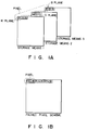
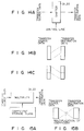
- Expression schemes for color image information employed by such apparatuses are classified into various types according to storage forms. There are, for example, a plane independent scheme shown in Fig. 1A and a packed pixel scheme shown in Fig. 1B.
- the plane independent scheme R, G, and B components of each pixel constituting image information are respectively stored in storage means 1, 2, and 3 in units of R, G, and B planes as pixel color components, i.e., in units of colors.
- R, G and B planes are sequentially stored in units of pixels.
- image information varies in form, e.g., the data width and number of constituent bits of each pixel and plane to be stored in a storage means.
- the present invention has been made to solve the above drawbacks that a long processing time is required to transfer image information between processing means having different image information forms, limitations are inevitably imposed on the types of forms which can be processed in one apparatus, and transfer of image information between arbitrary units having different image information forms is inefficient and cannot be practically performed, and it is an object of the present invention to provide an image information processing apparatus which can perform high-speed transfer processing between arbitrary processing means or units having different image information forms, and can realize a flexible system.
- an image information processing apparatus comprising first means for storing transfer source form information and supplying them; second means for storing transfer destination from information and supplying them; means for extracting pixel and plane data designated by the first storing means form transfer source data inputted; means for converting a width of a plane data received from the extracting means when plane data received from the first storing means is different from that received from the second storing means; and means for reformatting the transfer source data extracted by the extracting means into a form designated by the second storing means and outputting the form as transfer destination data.
- an image information processing apparatus comprising a plurality of means for processing image information and having different image information forms such as pixel width and plane width, means for transferring image information between the processing means, means for detecting an image information form such as a pixel width and plane width in processing means at a transfer source and an image information form such as a pixel width and plane width in processing means at a transfer destination when image information is transferred between the processing means by the transfer means, and means for changing the image information form such as the pixel width and plane width from the processing means at the transfer source into the image information form such as the pixel width and plane width of the processing means at the transfer destination in accordance with the image information forms of the transfer source and the transfer destination, detected by the form detecting means, when the transfer means transfers the image information between the processing means having the different image information forms.
- a plurality of processing means which process image information and have different image information forms such as a pixel width and plane width are arranged.
- Transfer means transfers image information between the processing means.
- form detecting means detects an image information form such as a pixel width and plane width in processing means at a transfer source and an image information form such as a pixel width and plane width in processing means at a transfer destination.
- changing means changes the image information form such as a pixel width and plane width from the processing means at the transfer source into the image information form such as a pixel width and plane width of the processing means at the transfer destination in accordance with the image information forms of the transfer source and the transfer destination, detected by the form detecting means.
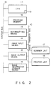
- Fig. 2 shows an electronic filing apparatus as the image processing apparatus of the present invention.
- the electronic filing apparatus comprises a central processing unit (CPU) 11 for controlling the overall apparatus, a program memory 12 for storing control information prescribing processing performed by the CPU 11, a reformatting means 13 for converting the format (form) of image information to be transferred, an image input means 14 serving as a scanner interface for interfacing with a scanner unit 17, an image output means 15 serving as a printer interface for interfacing with a printer unit 18, and an image storage means 16.
- the image information storage means 16 may be constituted by either a general memory device or a large-capacity recording medium such as an optical disk unit.
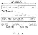
- Fig. 3 shows a general form of a data format for one transfer unit of color image information.
- Data of one transfer unit is constituted by a combination of a pixel count (n), a plane data count (m), and a plane data width (l).
- One transfer unit is constituted by information of a plurality of pixels.
- information of one pixel is constituted by information of a plurality of planes.
- Fig. 3 shows a general form, in practice, the form of one transfer unit varies depending on a processing means or a unit.
- one transfer unit may be constituted by only one pixel or only one plane. That is, the form of a transfer unit depends on the hardware of each unit and greatly varies.
- R (red) information, G (green) information, and B (blue) information, or Y (yellow) information, M (magenta) information, C (cyan) information, and B (black) information are prepared.
- the respective planes may be constituted by different numbers of bits. For example, if the pixel data width is set to be 8 bits, bit assignment is generally performed such that 3 bits are assigned to R (red) information; 3 bits, to G (green) information; and 2 bits, to B (blue) information.
- the reformatting means 13 serves to perform high-speed conversion processing of a transfer form in a case wherein image information is to be transferred between processing means or units to which image information must be transferred in different forms.
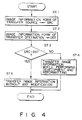
- step ST1 if the form (SRC) (step ST1) of image information of a transfer source coincides with the form (DST) (step ST2) of image information of a transfer destination (step ST3), the CPU 11 directly transfers the image information from the transfer source to the transfer destination (step ST5). If the forms of image information differ from each other (step ST3), the CPU 11 transfers the image information from the transfer source to the transfer destination through the reformatting means 13 (after the execution of development and reformation) (step ST4).
- Reference numeral 11a denotes an internal memory.
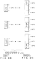
- Figs. 5A to 5D respectively show transfer states accompanying conversion of the form of image information between the respective means constituting this embodiment.
- Fig. 5A shows a case wherein image information read by the scanner unit 17 is transferred to the image information storage means 16 through the image input means 14 and the reformatting means 13.
- Fig. 5B shows a case wherein image information stored in the image information storage means 16 is transferred to the printer unit 18 through the reformatting means 13 and the image output means 15.
- Fig. 5C shows a case wherein image information read by the scanner unit 17 is stored in the image information storage means 16 through the image input means 14 and the reformatting means 13, and the image information stored in the image information storage means 16 is further transferred to the printer unit 18 through the image output means 15.
- Fig. 5D shows a case wherein image information stored in the image information means 16 is transferred to the image information storage means 16 through the reformatting means 13.
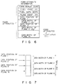
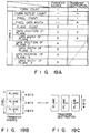
- Form attribute information for defining the form of image information to be transferred which is used by the reformatting means 13, is constituted by a form repeat count, a pixel count (n), a pixel data width, a plane count (m), the data positions of planes 1 to N, and the data widths (l) of the planes 1 to N, as shown in Fig. 6.
- a form repeat count defines the number of times of transfer in which "form attribute" defined by a pixel count (n) and the like defined below is repeated. For example, if the form repeat count is "3", it means that the same form attribute is continuously repeated three times.
- a pixel count (n) is the number of pixels included in one transfer unit.
- a pixel data width is the number of data bits constituting one pixel.
- a plane count (m) is the number of image planes for expanding one pixel.
- the data positions and data widths (l1, l2,..., ln) of the planes 1 to N respectively represent the bit positions and bit widths of the respective plane information included in one pixel information, which are expressed by relative positions within one pixel, as shown in Fig. 7.
- the form attribute information of a transfer source and that of a transfer destination are both stored in the internal memory 11a of the CPU 11.
- the CPU 11 determines whether the form attribute information of the transfer source and that of the transfer destination, stored in the internal memory 11a, coincide with each other.
- the reformatting means 13 performs conversion processing of the image information in accordance with the determination result, and transfers the resulting information.
- form attribute information stored in the internal memory 11a has attribute information "form count” for defining the number of forms, such as “form 1", “form 2",..., for a transfer source and a transfer destination each, thus allowing a plurality of types of form attribute information, such as the one shown in Fig. 6, to be defined.
- the first form information i.e., "form 1”
- the first form information is selected (step ST11).
- Transfer processing is continuously repeated the number of times corresponding to a form repeat count defined in this form information (step ST12). If the number of times of transfer reaches the form repeat count (step ST13), the form attribute information is updated (step ST14). If update processing is performed the number of times corresponding to "form count" (step ST15), the first form attribute information is selected again (step ST11). Subsequently, transfer is performed while update of form attribute information is sequentially repeated.
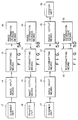
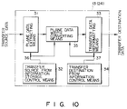
- the reformatting means 13 comprises a plane data extracting means 31, a transfer source form information storage control means 32, a transfer data reformatting means 33, a transfer destination form information storage control means 34, and a plane data width converting means 35.
- image processing is basically performed such that image information of a transfer source (transfer source data) is decomposed into pixels and planes in the input stage, and is reformatted to conform to the form of the transfer destination in the output stage.
- the plane data extracting means 31 extracts pixel and plane information designated by the transfer source form information storage control means 32.
- the transfer data reformatting means 33 reformats the transfer source data extracted by the plane data extracting means 31 into a form designated by the transfer destination form information storage control means 34, and outputs the resulting transfer destination data.
- the plane data width converting means 35 performs conversion processing when the bit count of the plane data of the transfer source is different from that of the transfer destination.
- the form information shown in Fig. 8 is stored in the transfer source form information storage control means 32 and the transfer destination form information storage control means 34.
- the reformatting means 13 includes a control means for executing the above-described processing in accordance with the form information.
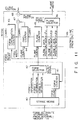
- the transfer source form information storage control means 32 comprises a storage means 40, a form counter 41, a form selector 42, a form repeat counter 43, a pixel counter 44, a plane counter 45, a plane selector 46, a multiplier 47, and an adder 48.
- the storage means 40 serves to store form attribute information of a transfer source, supplied from the internal memory 11a.
- the form counter 41 is a counter having a base defined by "form count" of form attribute information. When the form count is 2, the counter 41 serves as a binary counter. When the form count is 3, the counter 41 is serves as a ternary counter.
- the form repeat counter 43, the pixel counter 44, and the plane counter 45 all operate as preset counters.
- the form selector 42 is a selector for selecting one of form attribute information in accordance with the count value of the form counter 41.
- a form repeat count, a pixel count, a pixel width, and a plane count are respectively set in the form repeat counter 43, the pixel counter 44, the multiplier 47, and the plane counter 45.
- Each plane information of the form attribute information selected by the form selector 42 is output from the plane selector 46.
- a set of plane information supplied from the form selector 42 is selected and output to the plane selector 46 in accordance with the count value of the plane counter 45.
- a control signal (corresponding to a data transfer clock) of a control line 49 is activated by the CPU 11 to sequentially update the count value of each of the counters 45, 44, and 43.
- the counter 45, 44, and 43 are all initially set to be "0".
- "form 1" is selected first by the form selector 42.
- the plane information of plane 1 of pixel 1 is selected and input to the plane counter 45.
- the count value of the plane counter 45 is set to be "1"
- the plane information of plane 2 of "form 1" is selected.
- the pixel counter 44 When a predetermined number of planes are counted, the pixel counter 44 is updated, and the plane information of pixel 2 is selected. In this case, each pixel has the same plane arrangement, and the same plane width is repeatedly used for the respective pixels. Therefore, it is only required that the plane position be changed by the pixel width. For this reason, the pixel width and the count value of the pixel counter 44 are multiplied with each other by the multiplier 47, and the obtained product and the relative position of the plane selected by the plane selector 46 are added together by the adder 48, thus calculating the position of the designated plane in the transfer data. This operation is repeated by the number of times corresponding to the pixel count, and counting of the form repeat counter 43 is performed by the number of times corresponding to the repeat count. Thereafter, the form counter 41 is updated to select the next form attribute information. The same processing is subsequently performed with respect to "form 2", "form 3",....
- the transfer destination form information storage control means 34 has the same arrangement as that of the transfer source form information storage control means 32. However, the storage means 40 serves to store the form attribute information of a transfer destination.
- plane position information and plane width information output from the transfer source form information storage control means 32 are supplied to the plane data extracting means 31 and the plane data width converting means 35.
- Plane position information and plane width information output from the transfer destination form information storage control means 34 are supplied to the transfer data reformatting means 33 and the plane data width converting means 35.
- the plane data extracting means 31 and the transfer data reformatting means 33 are constituted by, e.g., a barrel shifter shown in Fig. 12. With this arrangement, a shift operation corresponding to the difference between a plane position and a plane width is performed, as shown in Fig. 13.
- the difference between the plane data extracting means 31 and the transfer data reformatting means 33 indicates the direction of a shift operation.
- a shift operation from a state (a) in Fig. 13 to a state (b) in Fig. 13 is performed by the transfer source form information storage control means 32, whereas a reverse shift operation is performed by the transfer destination form information storage control means 34.
- the plane data width converting means 35 in Fig. 10 serves to adjust a plane data width (l).
- the plane data width converting means 35 is constituted by, e.g., a shifter as shown in Fig. 14A, a multiplier as shown in Fig. 15A, an adder as shown in Fig. 16A, or a conversion table as shown in Fig. 17A.
- the means 35 is designed to perform high-speed conversion.
- Fig. 14A shows a scheme in which a shifter is simply closed, and transfer source data is properly shifted to conform to transfer destination data. As shown in Figs. 14B and 14C, whether the upper or lower portion of transfer source data is validated is arbitrarily designated by designating the direction of a shift operation.
- Figs. 14A shows a scheme in which a shifter is simply closed, and transfer source data is properly shifted to conform to transfer destination data.
- Figs. 14B and 14C whether the upper or lower portion of transfer source data is validated is arbitrarily
- 15A and 15B show a scheme in which transfer destination data is multiplied by a coefficient to be matched with transfer source data. For example, when 4-bit data is to be simply expanded to 5-bit data, the 4-bit data is multiplied by 31/15.
- Figs. 16A and 16B show a scheme in which a coefficient is added to transfer destination data.
- Figs. 17A and 17B show a scheme in which transfer destination data is obtained by referring to a conversion table on the basis of transfer source data. This scheme is effective when the bit width is small.
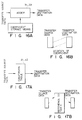
- Transfer processing in the state shown in Fig. 18A will be described first, in which one type of form attribute information is used, one transfer destination is present, and no plane definition is given. In this case, since only one type of form is set, an arbitrary form repeat count can be set. As a result, transfer source image data shown in Fig. 18B is converted into image data shown in Fig. 18C to be output to the transfer destination. More specifically, the transfer source data and the transfer destination data are the same in pixel data width, plane count, the data position of plane 1, and the data width of plane 1, but are different in that the pixel count of the transfer source data is "4" and that of the transfer destination data is "1". Therefore, data is transferred from the transfer source in units of four pixels, whereas data is transferred to the transfer destination in units of pixels.
- Transfer processing in the state shown in Fig. 19A will be described below, in which one type of form attribute information is used, one transfer destination is present, and the plane data included in one pixel is transferred in units of planes. In this case, since only one type of form is set, an arbitrary form repeat count can be set.
- 1-pixel image data of the transfer source data shown in Fig. 19B
- the pixel data width is changed from "11" to "4" between the transfer source and the transfer destination; and the plane count, from "3" to "1".
- the data positions of planes 1, 2, and 3 are “0”, “4", and “7”, respectively, and the data widths of planes 1, 2, and 3 are “4", "3", and “4", respectively.
- the data position of plane 1 is "0”, and the data width of plane 1 is "4". Therefore, the data (11 bits) of the three planes of one pixel is collectively transferred from the transfer source, whereas the one-pixel data is transferred to the transfer destination in units of plane data (4 bits).
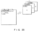
- the plane data of one-page image information are respectively transferred to three memories corresponding to the colors of the three types of planes and are stored therein. More specifically, the image information of the three types of planes, i.e., R (red), G (green), and B (blue) planes constituting each pixel transferred from the transfer destination source, are respectively transferred to different memories, respectively prepared for R (red), G (green), and B (blue), to be stored therein.
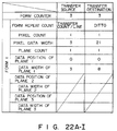
- Transfer processing in the state shown in Fig. 20A will be described below, in which there are three types of form attribute information, one transfer source, and three transfer destinations, and the plane data included in one pixel are transferred in units of planes while each plane data position is defined.
- an arbitrary form repeat count can be set.
- the form count of each transfer destination is set to be "1".
- 1-pixel image data of the transfer source shown in Fig. 20B
- image data in units of planes shown in Fig. 20C
- the resulting data are then output to each transfer destination.
- the pixel data width is changed from “11" to "12" between the destination source and each transfer destination; and the plane count, from “3" to "1".
- the data positions of planes 1, 2, and 3 are “0", “4", and “7”, respectively, and the data widths of planes 1, 2, and 3 are “4", "3", and "4", respectively.
- the data position and data width of plane 1 are “0" and "4", respectively.
- the data position and data width of plane 1 are "4" and "4", respectively.
- the data position and data width of plane 1 are "8" and "4", respectively.
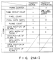
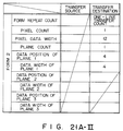
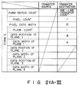
- Transfer processing in the state shown in Fig. 21A will be described below, in which there are three types of form attribute information, one transfer source, and three transfer destinations, and data is transferred in units of planes while each plane data position is defined.
- an arbitrary form repeat count can be set. Since the form count of each transfer destination is updated every time form attribute information corresponding to one line is transferred, the repeat count is set to coincide with a one-line transfer count.
- image data transferred from the transfer source in units of planes (4 bits), shown in Fig. 21B are converted into image data in units of planes (12 bits), shown in Fig. 21C, with the plane data positions respectively defined. The resulting data are then transferred to each transfer destination.
- the pixel data width is changed from "4" to "12" between the transfer source and each transfer destination, and the plane count remains the same.
- the data position and data width of plane 1 are “0” and “4", respectively.
- the data position and data width of plane 1 are “0” and "4", respectively.
- the data position and data width of plane 1 are “4" and "4", respectively.
- the data position and data width of plane 1 are "8” and "4", respectively. Therefore, the data (4 bits) of one plane is transferred from the transfer source, whereas the data (4 bits) of each plane of one pixel is transferred, as 12-bit data having actual data assigned to one of three different positions, to each transfer destination.
- plane data from the transfer source are transferred in units of scanning lines of an image. Since information to each transfer destination is updated every time a transfer operation corresponding to one line is performed, the repeat count is set to coincide with a one-line transfer count. In contrast to this, since the same form information is used for the transfer source, the form count is set to be "1" to perform transfer processing with the same attribute information.
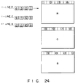
- R (red) plane data, G (green) plane data, and B (blue) plane data can be respectively transferred to three memories respectively prepared for R (red), G (green), and B (blue), in units of lines, to be stored therein. More specifically, when the R (red) plane data of one line are sequentially supplied from the transfer source to the reformatting means 13 in units of planes, the data width of each plane data is increased to 12 bits, as shown in Fig. 21A, and the data are sequentially stored in the memory for R (red).
- the data width of each plane data is increased to 12 bits, as shown in Fig. 21A, and the data are sequentially stored in the memory for G (green).
- the data width of each plane data is increased to 12 bits, as shown in Fig. 21A, and the data are sequentially stored in the memory for B (blue).
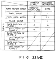
- Figs. 22A, 22B, and 22C show a case wherein a condition that the information form of a transfer source is updated for every line is added to the conditions shown in Figs. 21A, 21B, and 21C.
- the transfer source and the transfer destination may simply exchange the form attribute information.
- the CPU 11 stores form attribute information, set in the scanner unit 17, in the internal memory 11a, and also stores form attribute information, set in the image information storage means 16, in the internal memory 11a.
- the form attribute information in the scanner unit 17 is stored, as transfer source information, in the internal memory 11a, while the form attribute information in the image information storage means 16 is stored, as transfer destination information, in the internal memory 11a (see Fig. 8).
- the CPU 11 checks whether the form attribute information of the transfer source coincides with that of the transfer destination. If they perfectly coincide with each other, the image information read by the scanner unit 17 is transferred to the image information storage means 16 through the image input means 14 and the reformatting means 13. In this manner, the image information read by the scanner unit 17 is stored in the image information storage means 16.
- the CPU 11 If the form attribute information of the transfer source does not coincide with that of the transfer destination, the CPU 11 outputs the form attribute information of the transfer source and that of the transfer destination to the reformatting means 13, and outputs the image information read by the scanner unit 17 to the reformatting means 13 through the image input means 14. Subsequently, the reformatting means 13 converts the image information from the scanner unit 17 as the transfer source into image information conforming to the form attribute information of the transfer destination in accordance with the form attribute information of the transfer source and that of the transfer destination. With this operation, the form of the image information read by the scanner unit 17 is changed by the reformatting means 13, and the resulting information is stored in the image information storage means 16.
- the form attribute information of a transfer destination and that of a transfer source are automatically set when image information is to be transferred.
- the respective contents of form attribute information such as a repeat count, may be designated through a designating means, e.g., a keyboard, using a display means.
- image information is be transferred between processing means or units having different image information forms, e.g., the pixel width and plane width of image information
- the image information is converted by the reformatting means using the form attribute information of a transfer source and that of a transfer destination.
Landscapes
- Engineering & Computer Science (AREA)
- Multimedia (AREA)
- Signal Processing (AREA)
- Processing Or Creating Images (AREA)
- Image Processing (AREA)
Applications Claiming Priority (2)
| Application Number | Priority Date | Filing Date | Title |
|---|---|---|---|
| JP340423/90 | 1990-11-30 | ||
| JP02340423A JP3110041B2 (ja) | 1990-11-30 | 1990-11-30 | 画像情報処理装置 |
Publications (2)
| Publication Number | Publication Date |
|---|---|
| EP0488028A2 true EP0488028A2 (de) | 1992-06-03 |
| EP0488028A3 EP0488028A3 (en) | 1992-12-16 |
Family
ID=18336815
Family Applications (1)
| Application Number | Title | Priority Date | Filing Date |
|---|---|---|---|
| EP19910119733 Ceased EP0488028A3 (en) | 1990-11-30 | 1991-11-19 | Color image information processing apparatus |
Country Status (3)
| Country | Link |
|---|---|
| US (1) | US5280578A (de) |
| EP (1) | EP0488028A3 (de) |
| JP (1) | JP3110041B2 (de) |
Families Citing this family (6)
| Publication number | Priority date | Publication date | Assignee | Title |
|---|---|---|---|---|
| JP3055917B2 (ja) * | 1990-05-22 | 2000-06-26 | 日本電気株式会社 | データ転送制御装置 |
| US5422657A (en) * | 1993-09-13 | 1995-06-06 | Industrial Technology Research Institute | Graphics memory architecture for multimode display system |
| US5710604A (en) * | 1996-02-09 | 1998-01-20 | Texas Instruments Incorporated | Video memory device for color-sequential-type displays |
| US6243081B1 (en) * | 1998-07-31 | 2001-06-05 | Hewlett-Packard Company | Data structure for efficient retrieval of compressed texture data from a memory system |
| KR101226696B1 (ko) | 2011-10-31 | 2013-01-25 | 장성용 | 원터치 장착식 인조네일 |
| WO2015019394A1 (ja) * | 2013-08-05 | 2015-02-12 | 富士通株式会社 | 電子装置 |
Family Cites Families (6)
| Publication number | Priority date | Publication date | Assignee | Title |
|---|---|---|---|---|
| JPS6057457A (ja) * | 1983-09-07 | 1985-04-03 | Ricoh Co Ltd | Dma装置 |
| JPS61159686A (ja) * | 1985-01-07 | 1986-07-19 | 株式会社日立製作所 | 画像表示装置 |
| JPS62297977A (ja) * | 1986-06-17 | 1987-12-25 | Toshiba Corp | 画像情報記憶検索装置 |
| US4965750A (en) * | 1987-03-31 | 1990-10-23 | Hitachi, Ltd. | Graphic processor suitable for graphic data transfer and conversion processes |
| JPH01205260A (ja) * | 1988-02-12 | 1989-08-17 | Toshiba Corp | 文書整形装置 |
| JPH0292155A (ja) * | 1988-09-29 | 1990-03-30 | Sony Corp | 画像読み取り装置 |
-
1990
- 1990-11-30 JP JP02340423A patent/JP3110041B2/ja not_active Expired - Fee Related
-
1991
- 1991-11-19 EP EP19910119733 patent/EP0488028A3/en not_active Ceased
- 1991-11-26 US US07/797,903 patent/US5280578A/en not_active Expired - Fee Related
Also Published As
| Publication number | Publication date |
|---|---|
| EP0488028A3 (en) | 1992-12-16 |
| JP3110041B2 (ja) | 2000-11-20 |
| JPH04205667A (ja) | 1992-07-27 |
| US5280578A (en) | 1994-01-18 |
Similar Documents
| Publication | Publication Date | Title |
|---|---|---|
| US4992861A (en) | Color image reproduction apparatus having a digitally operated look-up table constructed by means of a least squares algorithm | |
| US5930388A (en) | Color image processing apparatus | |
| US5245445A (en) | Image processing apparatus | |
| US5646752A (en) | Color image processing apparatus which uses private tags to alter a predefined color transformation sequence of a device profile | |
| US5225911A (en) | Means for combining data of different frequencies for a raster output device | |
| KR100364942B1 (ko) | 다차원데이타변환장치및방법 | |
| EP0553549B1 (de) | Architektur zur Übertragung eines Bildelementenstroms | |
| US5610732A (en) | Image processing apparatus having unevenly gamut dividing color-converting function | |
| US7215440B2 (en) | Fast interpolation of large color lookup tables | |
| US5280578A (en) | Color image information processing apparatus capable of high-speed processing image information in different form | |
| EP0755022B1 (de) | Apparat zum editieren von bildern | |
| US5576849A (en) | Image data transformation apparatus and image entry apparatus | |
| JPH01321578A (ja) | 画像表示装置 | |
| US6049400A (en) | Non-symmetric tetrahedral and non-symmetric pruned tetrahedral interpolation | |
| JPH0439780A (ja) | 画像合成装置 | |
| JPS5991489A (ja) | 表示装置 | |
| US5760762A (en) | Color image processing method and color image processing | |
| US5109272A (en) | Method of superimposing color images and color image processing apparatus | |
| EP0404397B1 (de) | Bildverarbeitungssystem | |
| JPS6213674B2 (de) | ||
| KR100429859B1 (ko) | 전자 줌 시스템의 확대 영역 결정방법 및 장치 | |
| JPH0463063A (ja) | 誤差拡散回路 | |
| JPH04205670A (ja) | 画像情報処理装置 | |
| JPH04205669A (ja) | 画像情報処理装置 | |
| JPH01229382A (ja) | 画像処理システム |
Legal Events
| Date | Code | Title | Description |
|---|---|---|---|
| PUAI | Public reference made under article 153(3) epc to a published international application that has entered the european phase |
Free format text: ORIGINAL CODE: 0009012 |
|
| 17P | Request for examination filed |
Effective date: 19911119 |
|
| AK | Designated contracting states |
Kind code of ref document: A2 Designated state(s): DE FR GB NL |
|
| PUAL | Search report despatched |
Free format text: ORIGINAL CODE: 0009013 |
|
| AK | Designated contracting states |
Kind code of ref document: A3 Designated state(s): DE FR GB NL |
|
| 17Q | First examination report despatched |
Effective date: 19941114 |
|
| STAA | Information on the status of an ep patent application or granted ep patent |
Free format text: STATUS: THE APPLICATION HAS BEEN REFUSED |
|
| 18R | Application refused |
Effective date: 19950622 |