EP0486481B1 - Apparatus for gripping balls containing plants - Google Patents
Apparatus for gripping balls containing plants Download PDFInfo
- Publication number
- EP0486481B1 EP0486481B1 EP92200413A EP92200413A EP0486481B1 EP 0486481 B1 EP0486481 B1 EP 0486481B1 EP 92200413 A EP92200413 A EP 92200413A EP 92200413 A EP92200413 A EP 92200413A EP 0486481 B1 EP0486481 B1 EP 0486481B1
- Authority
- EP
- European Patent Office
- Prior art keywords
- gripping
- ball
- container
- vertical direction
- movable
- Prior art date
- Legal status (The legal status is an assumption and is not a legal conclusion. Google has not performed a legal analysis and makes no representation as to the accuracy of the status listed.)
- Expired - Lifetime
Links
- 210000000056 organ Anatomy 0.000 claims description 35
- 230000008719 thickening Effects 0.000 description 1
Images
Classifications
-
- A—HUMAN NECESSITIES
- A01—AGRICULTURE; FORESTRY; ANIMAL HUSBANDRY; HUNTING; TRAPPING; FISHING
- A01G—HORTICULTURE; CULTIVATION OF VEGETABLES, FLOWERS, RICE, FRUIT, VINES, HOPS OR SEAWEED; FORESTRY; WATERING
- A01G23/00—Forestry
- A01G23/02—Transplanting, uprooting, felling or delimbing trees
-
- A—HUMAN NECESSITIES
- A01—AGRICULTURE; FORESTRY; ANIMAL HUSBANDRY; HUNTING; TRAPPING; FISHING
- A01G—HORTICULTURE; CULTIVATION OF VEGETABLES, FLOWERS, RICE, FRUIT, VINES, HOPS OR SEAWEED; FORESTRY; WATERING
- A01G9/00—Cultivation in receptacles, forcing-frames or greenhouses; Edging for beds, lawn or the like
- A01G9/08—Devices for filling-up flower-pots or pots for seedlings; Devices for setting plants or seeds in pots
- A01G9/086—Devices for repotting
-
- Y—GENERAL TAGGING OF NEW TECHNOLOGICAL DEVELOPMENTS; GENERAL TAGGING OF CROSS-SECTIONAL TECHNOLOGIES SPANNING OVER SEVERAL SECTIONS OF THE IPC; TECHNICAL SUBJECTS COVERED BY FORMER USPC CROSS-REFERENCE ART COLLECTIONS [XRACs] AND DIGESTS
- Y10—TECHNICAL SUBJECTS COVERED BY FORMER USPC
- Y10S—TECHNICAL SUBJECTS COVERED BY FORMER USPC CROSS-REFERENCE ART COLLECTIONS [XRACs] AND DIGESTS
- Y10S47/00—Plant husbandry
- Y10S47/901—Plant container with flats, filling, planting, or conveying
Definitions
- the present invention relates to the field of gripping apparatus for plants, and relates in particular to an apparatus for removing a ball comprising a plant from a cavity provided in a container, the apparatus comprising:
- Such known apparartuses generally have the disadvantage, that as a consequence of a too large pushing force, which is required to remove the ball from the container, the ball is pulverised or the plant is damaged. It also may happen that it is not well possible to grip the ball, because the plant is approached from above. Of course such damages are undesired.
- the aim of the present invention is to provide an apparatus in which it is avoided that neither the plant nor the ball is damaged, and wherein the ball is gripped in a sure way, and wherein the position of the ball is reproducable.
- the guiding channel and the pushing element both have a star-configuration, comprising at least three gripping organs which are able to grip the ball at its sides, when it is substantially above the upper side of the container, and that the pushing element comprises elongations extending substantially upward from the ends of the star and engaging the sides of the ball.
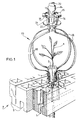
- the ball 2 comprising a plant 1 has been provided in a strip-shaped container 3.
- the upper side of this container 3 comprises an array of substantially cylindrical cavities 4, while the lower side of the strip-shaped container comprises a groove 5 extending in the longitudinal direction of the container.
- Concentric with each of the cylindrical cavities 4 a cross- or star-shaped through aperture has been provided which, as a consequence of the presence of the cavities 4 and of the grooves 5, is shown in the drawing in the shape of four grooves 6 extending radially from the cavities 4. These grooves extend over the full height of the strip-shaped container 3, including the groove 5.
- the strip-shaped containers 3 has been composed to a so-called tray 8 by means of connection strips 7. This facilitates the handling of such strips.
- the cavities 4 of the strip-shaped containers are filled with growing material and subsequently they are provided with a seed which actions are executed with apparatuses known per se, after which trays 8 comprising such strips are located in a propagator, after which the plants will germinate. As a consequence thereof, in most of the cavities 4 a ball 2 with a plant 1 will be present.
- a pushing organ 9 which comprises a vertical rod 10 driven in vertical direction by means of a lineair driving apparatus not depicted in the drawing, on which vertical rod 10 four radially extending levers 11 have been provided, while on each of the ends of the levers 11 an elongation 12 extending upwardly has been provided.
- the elongations 12 are beveled at their inner sides to facilitate the gripping of the balls 2.
- a gripping apparatus 13 which is located exactly above the pushing organ 9 and which is movable both in the horizontal and in the vertical direction for conveying the ball 2 with the plant 1 provided therein.
- the gripping apparatus 13 has been mounted to a hollow rod 14 being movable in substantially the vertical direction, at the lower side of which a bearing plate 15 has been provided.
- This bearing plate 15 comprises four notches distributed regularly over the circumference, in which notches substantially tangentially extending shafts 17 have been provided.
- a gripping lever 18 has been mounted around each of the shafts 17.
- Each of the gripping levers 18 extends from the shaft 17 initially downwardly, but also inwardly to some extend. Subsequently, the gripping lever extends substantially in radial direction outwardly, while after which a curve of about 180° is described, so that at the end of the curve the lever stretches inwardly. The last part of the gripping lever 18 stretches downwardly and forms the gripping part 19 of the gripping lever 18.
- An inner rod 20 extends through the hollow rod 14, at the lower side of which a guiding plate 21 has been provided.
- the guiding plate 21 comprises four apertures 22, through each of which the gripping lever 18 extends.
- the tray comprises strips 3 positioned such above a pushing organ 9, that a cavity 4 is exactly above the pushing organ 9.
- the driving apparatus will move the rod 10 with the levers 11 and elongations 12 thereof upwardly, so that these will move through the guiding grooves 6 provided in the strip-shaped container 3, so that the ball 2 is engaged at its lower side body arms 11 and at its side by the elongations 12, and is moved upwardly.
- ball 2 and the plant 1 provided is released from the cavity 4, until it is above the upper side of the strip-shaped container 3.
- the gripping apparatus 13 also positioned just above the pushing organ will be lowered by a driving apparatus not depicted in the drawings, after which the gripping parts 19 of the gripping levers 18 are on the level of the ball 2. Also the guiding plate 21 has been located in its lowest position, so that the gripping parts 19 are in their outer position. By moving the rod 20 upwardly and away from the guiding plate 21, the upper parts of the gripping levers 18 are drawn inwardly, so that also the gripping parts of the gripping levers 18 are drawn inwardly and these are gripping the ball 2. Care has to be taken that the gripping parts 19 grip between the elongations 12.
- the whole gripping apparatus 13 is moved upwardly and thus the plant can be transported to another position, for instance to a planting machine or to an apparatus for locating the ball and the plant in a bigger container.
- the pushing organ can be moved downwardly, after which the container can be relocated over one position and the next ball can be gripped.
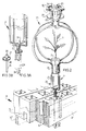
- fig. 2 The position, in which the ball has been moved until above the pushing organ by the gripping apparatus 13, is depicted in fig. 2.
- the embodiment shown in fig. 2 deviates from the embodiment depicted in fig. 1 to such an extend, that the pushing organ has been constructed differently.
- This pushing organ is depicted more in detail in fig. 3A and 3B.
- the embodiment shown in fig. 3A and 3B of the pushing organ comprises again a hollow rod 23, movable in the vertical direction which is split at its upper side into four gripping levers 24.
- the gripping levers 24 extend initially in subsequently vertical direction, but also somewhat in radial direction inwardly, in which each of the gripping arms comprises a vertical part, a horizontal part, directed radially outwardly, and the vertical part which is meant to grip the ball.
- an inner rod 26 extends, which comprises at its upper side a cross 27, as shown in fig. 3B, which is surrounded by a ring 28.
- a conical element 29 has been located.
- the gripping parts 25 of the gripping arms can be relocated in a radial direction, so that the pushing element according to this embodiment also has a gripping function which can be important in the case of some plants.
- thickenings 30 To offer room for the thickness of the gripping arms 24 guiding grooves provided in the strip-shaped containers 3 comprises thickenings 30.
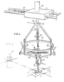
- each of the cavities 4 provided in the strip-shaped container 3 comprises only three guiding grooves 6. Consequently, it is necessary that the pushing organ 9 comprises three rods 10 comprising an elongation 12 at every end. Further, this embodiment equals the embodiment described with the help of fig. 1.
- the gripping apparatus deviates, however, substantially; the gripping apparatus has been mounted on a supporting element 31 which is movable over two rods 32.
- a driving rod 33 has been provided which is depicted only partially.
- a vertical rod 34 has been provided, which is movable in the vertical direction by means of a lineair driving organ 35.
- a plate 36 has been mounted, to which three rods 37 extending partially in the vertical direction downwardly and partially radially outwardly have been mounted.
- a U-shaped rod 38 has been provided, of which the legs extend downwardly in the vertical direction.
- Each of said rods 38 is connected with a ring 39.
- a shaft 55 has been mounted, around which rod 40 is movable.
- a gripping plate 41 has been provided, while at the other end of the rod 40 one end of the lineair driving organ 42 has been provided.
- This linear driving organ can take the shape of a hydraulic or pneumatic cilinder or a lineair electromotor.
- the working of the pushing organ 9 is therein equal to that of the pushing organ 9 described with the help of fig. 1.
- the supporting element 31 is positioned such, that the shaft 34 is precisely above the cavity 4.
- the lineair driving organs 42 have been pulled inwardly, so that the gripping plates 41 are in their outer position.
- the vertical rod 34 is moved downwardly, until the gripping plates 41 are at the level of the ball 2.
- the lineair driving organs will stretch, so that the gripping plates 41 will be moved inwardly and upwardly.
- the lineair driving organ 35 will move the vertical rod 34 such in downward direction, that this vertical component of movement is eliminated and the gripping plates 41 are moved in substantial horizontal direction. This movement is continued, until the ball has been gripped.
- the pushing organ can be moved downwardly, while the ball 2 with the plant 1 located therein can be transported to another position, for instance the position 43 depicted with dashed lines.
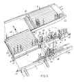
- Fig. 5 shows an application of the apparatus according to the present invention.
- a supply apparatus 44 for supplying strip-shaped containers 3 in the shape of trays and in the cavities 4, whereof plants 1 have been provided.
- a saw apparatus 45 To further process these trays 8 they are separated by a saw apparatus 45, so that separate strip-shaped containers 3 are developed.
- These are moved in a direction extending perpendicular to the original direction of supply by means of a transporting organ 46, after which they are subsequently step-wise drawn through a second pushing apparatus 47, wherein plants 1 located in the cavities 4 of the relevant strip-shaped container are examined.
- Such an examination apparatus can be composed by a light source 49 located at one side of the path to be traveled over by the plants and a light sensitive element located at the other side of the relevant path.
- This examination apparatus 48 determines whether a plant 1 is present in the cavity concerned, and when this is the case, whether the size of the plant is sufficient.
- the relevant ball and the plant 1 present therein is removed from the relevant cavity by means of a removal apparatus 51, after which a plant 1 from another strip-shaped container 3 is supplied by means of an apparatus depicted only schematically.
- the apparatus according to the present invention can also be used with a planting machine or in a machine for locating the plants in bigger containers.
Landscapes
- Life Sciences & Earth Sciences (AREA)
- Environmental Sciences (AREA)
- Biodiversity & Conservation Biology (AREA)
- Ecology (AREA)
- Forests & Forestry (AREA)
- Cultivation Receptacles Or Flower-Pots, Or Pots For Seedlings (AREA)
- Cultivation Of Plants (AREA)
- Farming Of Fish And Shellfish (AREA)
- Packaging Of Special Articles (AREA)
Applications Claiming Priority (3)
| Application Number | Priority Date | Filing Date | Title |
|---|---|---|---|
| NL8800040A NL8800040A (nl) | 1988-01-08 | 1988-01-08 | Inrichting voor het aangrijpen van van een plant voorziene kluiten. |
| NL8800040 | 1988-01-08 | ||
| EP88203012A EP0323674B2 (en) | 1988-01-08 | 1988-12-23 | Container for plants |
Related Parent Applications (1)
| Application Number | Title | Priority Date | Filing Date |
|---|---|---|---|
| EP88203012.5 Division | 1988-12-23 |
Publications (3)
| Publication Number | Publication Date |
|---|---|
| EP0486481A2 EP0486481A2 (en) | 1992-05-20 |
| EP0486481A3 EP0486481A3 (en) | 1992-09-02 |
| EP0486481B1 true EP0486481B1 (en) | 1994-09-21 |
Family
ID=19851564
Family Applications (2)
| Application Number | Title | Priority Date | Filing Date |
|---|---|---|---|
| EP92200413A Expired - Lifetime EP0486481B1 (en) | 1988-01-08 | 1988-12-23 | Apparatus for gripping balls containing plants |
| EP88203012A Expired - Lifetime EP0323674B2 (en) | 1988-01-08 | 1988-12-23 | Container for plants |
Family Applications After (1)
| Application Number | Title | Priority Date | Filing Date |
|---|---|---|---|
| EP88203012A Expired - Lifetime EP0323674B2 (en) | 1988-01-08 | 1988-12-23 | Container for plants |
Country Status (14)
| Country | Link |
|---|---|
| US (2) | US4970824A (enExample) |
| EP (2) | EP0486481B1 (enExample) |
| JP (1) | JPH01262734A (enExample) |
| KR (1) | KR960010574B1 (enExample) |
| AU (1) | AU622883B2 (enExample) |
| BR (1) | BR8900057A (enExample) |
| CA (1) | CA1297925C (enExample) |
| DE (2) | DE3884175T3 (enExample) |
| DK (1) | DK174742B1 (enExample) |
| ES (2) | ES2060448T3 (enExample) |
| FI (1) | FI90814C (enExample) |
| IL (1) | IL88891A0 (enExample) |
| NL (1) | NL8800040A (enExample) |
| ZA (1) | ZA8924B (enExample) |
Families Citing this family (44)
| Publication number | Priority date | Publication date | Assignee | Title |
|---|---|---|---|---|
| EP0422704B1 (en) * | 1989-09-11 | 1995-03-29 | Synbra B.V. | Device for raising plants |
| CA2028290C (en) * | 1989-11-01 | 1996-12-17 | Aart Van Wingerden | Tray, apparatus and method for propagating, growing and handling plants |
| NL194111C (nl) * | 1990-04-05 | 2001-07-03 | Visser S Gravendeel Holding | Werkwijze voor het zijdelings aangrijpen van plantwortelkluiten. |
| JPH053734A (ja) * | 1990-11-30 | 1993-01-14 | Kirin Brewery Co Ltd | 培養苗選別積替装置 |
| US5247761A (en) * | 1991-01-03 | 1993-09-28 | Robotic Solutions, Inc. | Computer controlled seedling transfer apparatus |
| US5419080A (en) * | 1991-02-01 | 1995-05-30 | Gardener's Supply | Multi-celled tray for growing plants |
| NL9100301A (nl) * | 1991-02-20 | 1992-09-16 | Visser S Gravendeel Holding | Houder voor teeltmateriaal. |
| US5215550A (en) * | 1991-07-10 | 1993-06-01 | Sylvester M. Tesch, Jr. | Seedling array transplanter |
| FR2685852B1 (fr) * | 1992-01-07 | 1999-02-19 | Gerplant Automation | Dispositif de prehension et de transfert de plants en mottes. |
| FR2693344B1 (fr) * | 1992-07-10 | 1994-09-30 | Metalliques Floren Const | Machine de repiquage automatique de mini-mottes. |
| US5320649A (en) * | 1992-08-18 | 1994-06-14 | Holland James J | Plant transplant system |
| NL9302172A (nl) * | 1993-12-13 | 1995-07-03 | Flier Bv Geb | Werkwijze en inrichting voor het manipuleren van substraat met daarin opgenomen gewas. |
| FR2715531B1 (fr) * | 1994-02-02 | 1996-04-19 | Claude Ferrand | Dispositif de repiquage rapide de végétaux. |
| EP0712569B1 (en) * | 1994-11-17 | 2000-01-05 | YANMAR AGRICULTURAL EQUIPMENT Co., Ltd. | Transplanter |
| AU4634696A (en) * | 1995-01-10 | 1996-07-31 | Synbra B.V. | Method, device and set of several hollow bodies for extracting a plug out of a hollow body |
| US5557881A (en) * | 1995-02-21 | 1996-09-24 | Bouldin; Floyd | Seedling transplanter |
| US5860372A (en) * | 1995-02-21 | 1999-01-19 | Bouldin & Lawson, Inc. | Seedling transplanter with planting fingers |
| NL1001461C2 (nl) * | 1995-10-20 | 1996-08-23 | William Van Der Burg | Inrichting voor het uit een verzameltray verwijderen van daarin aanwezige plantjes om deze over te brengen in potjes. |
| FR2756451B1 (fr) * | 1996-11-29 | 1999-02-19 | Gerplant Automation | Procede de transfert de plants en mottes, et tete de prehension pour la mise en oeuvre de ce procede |
| FR2773943B1 (fr) | 1998-01-27 | 2000-04-07 | Gerplant Automation | Procede et installation de transplantation de plants en mottes |
| EP0948886A1 (fr) * | 1998-04-09 | 1999-10-13 | Gerplant Automation | Procédé de transfert de plants en mottes, et tête de préhension pour la mise en oeuvre de ce procédé |
| NL1013434C2 (nl) | 1999-11-01 | 2001-05-02 | Synprodo Plantpak B V | Houder voor in kluiten opgenomen planten. |
| US6405481B1 (en) | 2000-05-19 | 2002-06-18 | Robert Bautner | Quick release plant holder |
| WO2005013670A1 (en) * | 2003-07-29 | 2005-02-17 | Ultracell Limited | Automated planter |
| US7708732B2 (en) * | 2003-10-16 | 2010-05-04 | Nps Pharmaceuticals, Inc. | Methods of administering therapeutic injections |
| ITPI20040099A1 (it) * | 2004-12-24 | 2005-03-24 | Maurizio Pacini | Sistema di realizzazione di tappeto erboso mediante micro-plantule preradicate |
| NL2001120C2 (nl) * | 2007-12-21 | 2009-06-23 | Bruygom Constructie En App Nbo | Inrichting en werkwijze voor het overzetten van in substraat wortelende planten. |
| NL1035036C2 (nl) | 2008-02-18 | 2009-08-19 | Sluiter Techniek B V | Werkwijze voor het verpotten van planten, alsmede een plantkop en een inrichting voorzien van een plantkop. |
| NL1036276C2 (nl) * | 2008-12-03 | 2010-06-07 | Visser S Gravendeel Holding | Inrichting voor het bevatten van plantmateriaal en systeem voor verwerking daarvan. |
| NL1036440C2 (nl) * | 2009-01-21 | 2010-07-22 | Visser S Gravendeel Holding | Tray voor planten. |
| WO2011108924A1 (en) * | 2010-03-03 | 2011-09-09 | Klimrek I.E. B.V. | Method and device for performing an operation on a plant |
| JP4651743B1 (ja) * | 2010-03-12 | 2011-03-16 | 株式会社椿本チエイン | 植物栽培装置 |
| NL2006531C2 (nl) * | 2011-04-04 | 2012-10-08 | Vivi B V | Systeem en werkwijze voor het verwerken van plantmateriaal. |
| CN103430670A (zh) * | 2013-09-11 | 2013-12-11 | 中国船舶重工集团公司第七0四研究所 | 自动手指式取苗装置 |
| JP6285801B2 (ja) * | 2014-05-27 | 2018-02-28 | 株式会社椿本チエイン | 植物引込装置および植物株移植システム |
| CN105993333B (zh) * | 2016-07-29 | 2017-10-17 | 安徽井泉中药股份有限公司 | 一种根茎类中药材机器人专用智能种植机械手 |
| WO2018107176A1 (en) | 2016-12-09 | 2018-06-14 | Eden Works, Inc. (Dba Edenworks) | Methods systems and apparatus for cultivating densely seeded crops |
| CN107155695B (zh) * | 2017-06-27 | 2020-11-13 | 惠安县崇武镇洛妤茶具商行 | 一种种花装置 |
| US10307913B2 (en) * | 2017-07-27 | 2019-06-04 | Control & Power Systems, Inc. | Robotic gripper |
| WO2019144176A1 (en) * | 2018-01-23 | 2019-08-01 | Goldfields Collections Pty Ltd | Transplanting apparatus and method |
| CN108341561B (zh) * | 2018-05-03 | 2021-02-19 | 王一磊 | 一种城市规划人工生态绿岛 |
| CN108551922B (zh) * | 2018-05-03 | 2020-02-07 | 王一磊 | 一种城市规划生态绿岛系统 |
| CN108966934B (zh) * | 2018-07-17 | 2020-11-24 | 惠安权小白科技有限公司 | 一种园林用盆栽换土装置 |
| CA3163061A1 (en) * | 2019-12-31 | 2021-07-08 | Owen R. Barnes | Mushroom harvesting container funnel tray and sorting device |
Citations (3)
| Publication number | Priority date | Publication date | Assignee | Title |
|---|---|---|---|---|
| FR2356360A1 (fr) * | 1976-07-01 | 1978-01-27 | Agronomique Inst Nat Rech | Conteneur pour plants forestiers et d'ornement |
| EP0030873A1 (en) * | 1979-12-18 | 1981-06-24 | Southern Chemicals Limited | Plant propagating trays |
| DE3638312A1 (de) * | 1985-11-12 | 1987-05-14 | Nyugatmagyarorsza Fagazdas K | Verfahren und topfreihenausbildung insbesondere zur zuechtung von pflaenzlingen |
Family Cites Families (19)
| Publication number | Priority date | Publication date | Assignee | Title |
|---|---|---|---|---|
| US863621A (en) * | 1905-10-09 | 1907-08-20 | Lora M Medbury | Device for molding butter preparatively to cutting it into individual proportions. |
| US1053730A (en) * | 1912-09-06 | 1913-02-18 | Niels Pihl Jensen | Planting implement. |
| US1501965A (en) * | 1923-09-10 | 1924-07-22 | Walter C Moors | Weed extractor |
| FR1307813A (fr) * | 1961-12-12 | 1962-10-26 | élément tubulaire favorisant le développement des plantes | |
| US3386608A (en) * | 1967-05-15 | 1968-06-04 | Diller Kenneth | Multiple-cell molded plastic tray |
| FR2145024A5 (enExample) * | 1971-07-02 | 1973-02-16 | Lecuru Jacques | |
| US3931694A (en) * | 1974-06-13 | 1976-01-13 | Haig K. Krikorian | Planting flat |
| FR2320882A1 (fr) * | 1975-08-14 | 1977-03-11 | Monjo Jacques | Dispositif d'extraction de plateaux alveoles |
| US4006558A (en) * | 1975-09-11 | 1977-02-08 | Native Plants, Inc. | Seedling plant propagation container |
| US4130314A (en) * | 1977-08-25 | 1978-12-19 | Storm Donald W | Picker and loader for soft goods |
| SU829014A1 (ru) * | 1978-03-31 | 1981-05-15 | Украинский Ордена Знак Почета Научно- Исследовательский Институт Лесногохозяйства И Агролесомелиорацииим. Г.H.Высоцкого | Контейнерна лента дл выращивани ипОСАдКи СЕ НцЕВ C НЕОбНАжЕННОйКОРНЕВОй СиСТЕМОй |
| SE420456B (sv) * | 1980-02-15 | 1981-10-12 | Stora Kopparbergs Bergslags Ab | Plantodlingsenhet |
| FR2571208B1 (fr) * | 1984-10-05 | 1987-10-09 | Germaine Michel | Procede de prehension et de transfert de produits fragiles ou de produits accessibles uniquement par le haut |
| DE3507282A1 (de) * | 1985-03-01 | 1986-09-04 | Unima Maschinenbau Gmbh, 6603 Sulzbach | Vorrichtung zur aufnahme eines plattenfoermigen koerpers, insbesondere einer palette |
| FR2580457B1 (fr) * | 1985-04-19 | 1987-06-12 | Coquillot Denis | Dispositif extracteur d'articles en matiere tendre et/ou friable, tels que des plants comportant des mottes de terre |
| KR950011710B1 (ko) * | 1986-11-21 | 1995-10-09 | 반 윙거덴 아트 | 배양구를 이용하여 식물을 증식시키는 장치 및 방법 |
| FR2614499B1 (fr) * | 1987-04-28 | 1989-08-18 | Gerplant Automation | Dispositif de prehension et de transfert de plants en mottes |
| US4854075A (en) * | 1987-12-03 | 1989-08-08 | Greiling Farms Inc. | Plant tray |
| US4929010A (en) * | 1989-10-25 | 1990-05-29 | Lahti Gary P | Portable lifter |
-
1988
- 1988-01-08 NL NL8800040A patent/NL8800040A/nl not_active Application Discontinuation
- 1988-12-23 DE DE3884175T patent/DE3884175T3/de not_active Expired - Lifetime
- 1988-12-23 EP EP92200413A patent/EP0486481B1/en not_active Expired - Lifetime
- 1988-12-23 DE DE3851640T patent/DE3851640T2/de not_active Expired - Lifetime
- 1988-12-23 ES ES92200413T patent/ES2060448T3/es not_active Expired - Lifetime
- 1988-12-23 EP EP88203012A patent/EP0323674B2/en not_active Expired - Lifetime
- 1988-12-23 ES ES88203012T patent/ES2043795T5/es not_active Expired - Lifetime
- 1988-12-28 FI FI886011A patent/FI90814C/fi not_active IP Right Cessation
-
1989
- 1989-01-03 ZA ZA8924A patent/ZA8924B/xx unknown
- 1989-01-04 AU AU27704/89A patent/AU622883B2/en not_active Expired
- 1989-01-05 IL IL88891A patent/IL88891A0/xx not_active IP Right Cessation
- 1989-01-05 CA CA000587535A patent/CA1297925C/en not_active Expired - Lifetime
- 1989-01-06 BR BR898900057A patent/BR8900057A/pt not_active IP Right Cessation
- 1989-01-06 DK DK198900061A patent/DK174742B1/da not_active IP Right Cessation
- 1989-01-06 JP JP1001899A patent/JPH01262734A/ja active Granted
- 1989-01-09 KR KR1019890000168A patent/KR960010574B1/ko not_active Expired - Fee Related
- 1989-01-09 US US07/294,742 patent/US4970824A/en not_active Expired - Lifetime
-
1991
- 1991-01-18 US US07/642,551 patent/US5121955A/en not_active Expired - Lifetime
Patent Citations (3)
| Publication number | Priority date | Publication date | Assignee | Title |
|---|---|---|---|---|
| FR2356360A1 (fr) * | 1976-07-01 | 1978-01-27 | Agronomique Inst Nat Rech | Conteneur pour plants forestiers et d'ornement |
| EP0030873A1 (en) * | 1979-12-18 | 1981-06-24 | Southern Chemicals Limited | Plant propagating trays |
| DE3638312A1 (de) * | 1985-11-12 | 1987-05-14 | Nyugatmagyarorsza Fagazdas K | Verfahren und topfreihenausbildung insbesondere zur zuechtung von pflaenzlingen |
Also Published As
| Publication number | Publication date |
|---|---|
| FI886011A7 (fi) | 1989-07-09 |
| DE3851640D1 (de) | 1994-10-27 |
| EP0486481A2 (en) | 1992-05-20 |
| ES2060448T3 (es) | 1994-11-16 |
| ZA8924B (en) | 1989-10-25 |
| CA1297925C (en) | 1992-03-24 |
| JPH01262734A (ja) | 1989-10-19 |
| ES2043795T5 (es) | 1997-10-16 |
| EP0486481A3 (en) | 1992-09-02 |
| FI90814B (fi) | 1993-12-31 |
| EP0323674B2 (en) | 1997-07-23 |
| AU2770489A (en) | 1989-07-13 |
| KR960010574B1 (ko) | 1996-08-06 |
| BR8900057A (pt) | 1989-09-05 |
| FI90814C (fi) | 1994-04-11 |
| DK6189A (da) | 1989-07-09 |
| DE3884175T3 (de) | 1998-03-19 |
| ES2043795T3 (es) | 1994-01-01 |
| DE3884175T2 (de) | 1994-01-13 |
| US4970824A (en) | 1990-11-20 |
| JPH0522487B2 (enExample) | 1993-03-29 |
| IL88891A0 (en) | 1989-08-15 |
| KR890011524A (ko) | 1989-08-21 |
| AU622883B2 (en) | 1992-04-30 |
| EP0323674A3 (en) | 1990-01-17 |
| NL8800040A (nl) | 1989-08-01 |
| EP0323674A2 (en) | 1989-07-12 |
| US5121955A (en) | 1992-06-16 |
| DK6189D0 (da) | 1989-01-06 |
| DE3884175D1 (de) | 1993-10-21 |
| DK174742B1 (da) | 2003-10-13 |
| EP0323674B1 (en) | 1993-09-15 |
| DE3851640T2 (de) | 1995-02-09 |
Similar Documents
| Publication | Publication Date | Title |
|---|---|---|
| EP0486481B1 (en) | Apparatus for gripping balls containing plants | |
| US5911631A (en) | Seedling transplanter with easily detachable gripper | |
| FI69951C (fi) | Saett och anordning vid odling av plantor | |
| US3825126A (en) | Flower pot grate-tray | |
| EP0464954A2 (en) | Apparatus for transplant propagation | |
| US5203109A (en) | Apparatus for transplant propagation | |
| JP2933271B2 (ja) | 植物栽培装置 | |
| EP0063892A1 (en) | Apparatus and method for conditioning a tobacco mass | |
| JP3940815B2 (ja) | セル苗移植装置 | |
| FI97766B (fi) | Laite taimen käsittävän paakun poistamiseksi | |
| JPS63279725A (ja) | 定植装置 | |
| FI92453C (fi) | Menetelmä paakkutaimien käsittelemiseksi ja menetelmän yhteydessä käytettävä kasvatusalusta | |
| US20230217863A1 (en) | Dry Agricultural Trimmer | |
| EP4062750B1 (de) | Gewächshausanordnung | |
| FI84308C (fi) | Foerfarande och anordning foer foerpackning av taeckrotsplantor. | |
| EP0540620A1 (en) | Cutting and/or manoeuvring apparatus and methods | |
| JPS61231909A (ja) | 移植機 | |
| AU2002100155A4 (en) | Apparatus for pushing a plurality of articles from respective receptacles | |
| JPH0216563Y2 (enExample) | ||
| JPH05276805A (ja) | 成型苗移植装置 | |
| JP3053943U (ja) | セル苗移植装置 | |
| JPH05260811A (ja) | 苗の移植装置 | |
| Tillett et al. | An experimental automatic repotting machine for hardy ornamental nursery stock | |
| JPH02286014A (ja) | 苗の自動植え替え装置 | |
| BG98802A (bg) | Метод и корито за складирване за сушене на листана растения,по-точно листа на тютюн |
Legal Events
| Date | Code | Title | Description |
|---|---|---|---|
| PUAI | Public reference made under article 153(3) epc to a published international application that has entered the european phase |
Free format text: ORIGINAL CODE: 0009012 |
|
| AC | Divisional application: reference to earlier application |
Ref document number: 323674 Country of ref document: EP |
|
| AK | Designated contracting states |
Kind code of ref document: A2 Designated state(s): BE CH DE ES FR GB IT LI NL SE |
|
| PUAL | Search report despatched |
Free format text: ORIGINAL CODE: 0009013 |
|
| AK | Designated contracting states |
Kind code of ref document: A3 Designated state(s): BE CH DE ES FR GB IT LI NL SE |
|
| 17P | Request for examination filed |
Effective date: 19930301 |
|
| 17Q | First examination report despatched |
Effective date: 19940126 |
|
| GRAA | (expected) grant |
Free format text: ORIGINAL CODE: 0009210 |
|
| AC | Divisional application: reference to earlier application |
Ref document number: 323674 Country of ref document: EP |
|
| AK | Designated contracting states |
Kind code of ref document: B1 Designated state(s): BE CH DE ES FR GB IT LI NL SE |
|
| PG25 | Lapsed in a contracting state [announced via postgrant information from national office to epo] |
Ref country code: LI Effective date: 19940921 Ref country code: CH Effective date: 19940921 |
|
| REF | Corresponds to: |
Ref document number: 3851640 Country of ref document: DE Date of ref document: 19941027 |
|
| ET | Fr: translation filed | ||
| REG | Reference to a national code |
Ref country code: ES Ref legal event code: FG2A Ref document number: 2060448 Country of ref document: ES Kind code of ref document: T3 |
|
| ITF | It: translation for a ep patent filed | ||
| PG25 | Lapsed in a contracting state [announced via postgrant information from national office to epo] |
Ref country code: SE Effective date: 19941221 |
|
| REG | Reference to a national code |
Ref country code: CH Ref legal event code: PL |
|
| PLBE | No opposition filed within time limit |
Free format text: ORIGINAL CODE: 0009261 |
|
| STAA | Information on the status of an ep patent application or granted ep patent |
Free format text: STATUS: NO OPPOSITION FILED WITHIN TIME LIMIT |
|
| 26N | No opposition filed | ||
| REG | Reference to a national code |
Ref country code: GB Ref legal event code: IF02 |
|
| PGFP | Annual fee paid to national office [announced via postgrant information from national office to epo] |
Ref country code: NL Payment date: 20071231 Year of fee payment: 20 Ref country code: ES Payment date: 20071227 Year of fee payment: 20 |
|
| PGFP | Annual fee paid to national office [announced via postgrant information from national office to epo] |
Ref country code: IT Payment date: 20071228 Year of fee payment: 20 |
|
| PGFP | Annual fee paid to national office [announced via postgrant information from national office to epo] |
Ref country code: GB Payment date: 20071231 Year of fee payment: 20 |
|
| PGFP | Annual fee paid to national office [announced via postgrant information from national office to epo] |
Ref country code: DE Payment date: 20071231 Year of fee payment: 20 |
|
| PGFP | Annual fee paid to national office [announced via postgrant information from national office to epo] |
Ref country code: FR Payment date: 20071221 Year of fee payment: 20 |
|
| PGFP | Annual fee paid to national office [announced via postgrant information from national office to epo] |
Ref country code: BE Payment date: 20071231 Year of fee payment: 20 |
|
| BE20 | Be: patent expired |
Owner name: *VISSER 'S-GRAVENDEEL HOLDING B.V. Effective date: 20081223 |
|
| REG | Reference to a national code |
Ref country code: GB Ref legal event code: PE20 Expiry date: 20081222 |
|
| PG25 | Lapsed in a contracting state [announced via postgrant information from national office to epo] |
Ref country code: NL Free format text: LAPSE BECAUSE OF EXPIRATION OF PROTECTION Effective date: 20081223 |
|
| NLV7 | Nl: ceased due to reaching the maximum lifetime of a patent |
Effective date: 20081223 |
|
| REG | Reference to a national code |
Ref country code: ES Ref legal event code: FD2A Effective date: 20081224 |
|
| PG25 | Lapsed in a contracting state [announced via postgrant information from national office to epo] |
Ref country code: ES Free format text: LAPSE BECAUSE OF EXPIRATION OF PROTECTION Effective date: 20081224 |
|
| PG25 | Lapsed in a contracting state [announced via postgrant information from national office to epo] |
Ref country code: GB Free format text: LAPSE BECAUSE OF EXPIRATION OF PROTECTION Effective date: 20081222 |