EP0486460B1 - Einrichtung zur lösbaren Befestigung von an Lagerbehältern, Lagerregalen, Ladenmöbeln oder dergl. anzubringenden Anzeigeschildern - Google Patents
Einrichtung zur lösbaren Befestigung von an Lagerbehältern, Lagerregalen, Ladenmöbeln oder dergl. anzubringenden Anzeigeschildern Download PDFInfo
- Publication number
- EP0486460B1 EP0486460B1 EP19910890257 EP91890257A EP0486460B1 EP 0486460 B1 EP0486460 B1 EP 0486460B1 EP 19910890257 EP19910890257 EP 19910890257 EP 91890257 A EP91890257 A EP 91890257A EP 0486460 B1 EP0486460 B1 EP 0486460B1
- Authority
- EP
- European Patent Office
- Prior art keywords
- retention
- groove
- rail
- holding
- spring
- Prior art date
- Legal status (The legal status is an assumption and is not a legal conclusion. Google has not performed a legal analysis and makes no representation as to the accuracy of the status listed.)
- Expired - Lifetime
Links
- 238000003860 storage Methods 0.000 title claims description 37
- 239000000463 material Substances 0.000 claims description 10
- 238000003825 pressing Methods 0.000 claims description 10
- 238000003780 insertion Methods 0.000 claims description 5
- 230000037431 insertion Effects 0.000 claims description 5
- 210000001364 upper extremity Anatomy 0.000 claims description 4
- 230000014759 maintenance of location Effects 0.000 claims 46
- 210000001331 nose Anatomy 0.000 claims 5
- 210000002105 tongue Anatomy 0.000 description 82
- 239000002184 metal Substances 0.000 description 5
- 238000004026 adhesive bonding Methods 0.000 description 3
- 230000000875 corresponding effect Effects 0.000 description 3
- 230000010354 integration Effects 0.000 description 3
- 238000004519 manufacturing process Methods 0.000 description 3
- 238000009825 accumulation Methods 0.000 description 2
- 238000010276 construction Methods 0.000 description 2
- 230000002349 favourable effect Effects 0.000 description 2
- 230000002411 adverse Effects 0.000 description 1
- 230000015572 biosynthetic process Effects 0.000 description 1
- 238000011109 contamination Methods 0.000 description 1
- 239000003292 glue Substances 0.000 description 1
- 230000001771 impaired effect Effects 0.000 description 1
- 230000007704 transition Effects 0.000 description 1
- 238000003466 welding Methods 0.000 description 1
Images


Classifications
-
- G—PHYSICS
- G09—EDUCATION; CRYPTOGRAPHY; DISPLAY; ADVERTISING; SEALS
- G09F—DISPLAYING; ADVERTISING; SIGNS; LABELS OR NAME-PLATES; SEALS
- G09F3/00—Labels, tag tickets, or similar identification or indication means; Seals; Postage or like stamps
- G09F3/08—Fastening or securing by means not forming part of the material of the label itself
- G09F3/18—Casings, frames or enclosures for labels
- G09F3/20—Casings, frames or enclosures for labels for adjustable, removable, or interchangeable labels
- G09F3/204—Casings, frames or enclosures for labels for adjustable, removable, or interchangeable labels specially adapted to be attached to a shelf or the like
-
- G—PHYSICS
- G09—EDUCATION; CRYPTOGRAPHY; DISPLAY; ADVERTISING; SEALS
- G09F—DISPLAYING; ADVERTISING; SIGNS; LABELS OR NAME-PLATES; SEALS
- G09F3/00—Labels, tag tickets, or similar identification or indication means; Seals; Postage or like stamps
- G09F3/08—Fastening or securing by means not forming part of the material of the label itself
- G09F3/18—Casings, frames or enclosures for labels
- G09F3/20—Casings, frames or enclosures for labels for adjustable, removable, or interchangeable labels
- G09F3/201—Enclosures enveloping completely the labels
Definitions
- the invention relates to a device for releasably attaching to storage containers, storage racks, shop furniture or the like Stand in connection with the relevant sign to be fastened and hold it on the holding rail.
- Devices of the aforementioned type are known, for example GB-A-1 218 557, which are intended for use with the approximately C-shaped holding rails in cross-section, which are often arranged on the front edges of the shelves of storage racks; According to their C-shape, these rails have a groove on their lower and upper edge, while the middle area of these rails is open; one often inserts simple cards in such rails, which carry prices, but also uses such rails to hold holding bodies, which in turn carry display signs;
- Such holding bodies can be approximately plate-shaped bodies which run out in tongues on opposite sides and have a size which makes it possible to insert these holding bodies into the open central part of the C-shaped holding rails and then to rotate them by approximately 90 °, the on these bodies mutually opposite holding tongues come into engagement in the two grooves of the holding rail and the holding body is fixed in this way.
- the inventive device of the type mentioned is characterized in that the holding rail forms a single groove, one side surface of the groove starting from the entrance of the groove is substantially flat and the other side surface of the groove is undercut that the holding tongues holding lugs, holding ribs or the like .
- Wear which can be inserted into the undercut of the undercut groove side surface after the insertion of the retaining tongues into the groove, and that at least one spring is provided on the retaining tongues or on the display plate, which spring is attached to the storage container, storage rack, shop furniture or the like located behind the display plate or engages on the holding rail and presses the retaining tongues pushed into the groove towards the front, towards the undercut groove side surface, and thus the retaining lugs, retaining ribs or the like into the undercut of the undercut groove side surface presses.
- a variant here which also has a simple structure and corresponding properties, is characterized in that the spring acts on a pressure tongue which is attached to the back of the display plate or on a retaining tongue and projects into the groove when the retaining tongues are inserted into the groove, wherein the part of the pressing tongue protruding into the groove is pressed by the spring against the rear side surface of the groove.
- a pair or more pairs of retaining tongues are provided on the rear of the display sign. Furthermore, it is advantageous if a spring is arranged approximately centrally between the two retaining tongues of the respective pair of retaining tongues. It is also advantageous if a pair of retaining tongues with a leaf spring placed between them is arranged approximately in the middle of the rear of the display plate.
- a variant which is advantageous for a good fit is characterized in that the holding tongues are arranged in the vicinity of the two side edges of the display plate on the back of the latter.
- a further variant, which is particularly advantageous with regard to a good fit is characterized in that a pair of holding tongues with a spring placed between the holding tongues of each pair is arranged in the vicinity of the two side edges of the display plate on the rear side thereof.
- the result is a very simple, stable construction of the device, which also enables labor-saving production of the device, provided that the retaining tongues are integrally formed on the display plate.
- a particularly simple design can be obtained in that the holding tongues are formed by at least one bar projecting upwards above this edge at the upper edge of the display plate and carrying at least one holding lug or holding rib.
- the holding rail is a U-shaped profiled rail. It is advantageous for the attachment of the display plates to the holding rail in question if it is provided that the rear leg of the holding rail is wider than the front leg of the holding rail and projects downward beyond the entrance of the groove.
- An embodiment of the device which is advantageous in many cases for production, in which a good integration of the holding rail into the storage containers, storage racks, Shop furniture or the like can be achieved, which integration also offers advantages with regard to the architectural integration of the holding rail and furthermore also makes it easier to attach the display signs to the relevant holding rail, because a stepless transition from that surface of the storage container, storage rack, shop furniture or the like is simple.
- in front of or on which the relevant display plate is to be attached, in the groove formed with the holding rail can be achieved is characterized in that the holding rail is attached to a surface of a storage container, storage rack, shop furniture or the like.
- the holding rail is formed by a strip made of sheet metal or flat plastic material, which is bent upwards and protrudes away from the surface to which the holding rail is attached and is bent back at its free edge to form the undercut of the front groove side surface.
- the holding rail is formed by the edge region of a cover made of sheet metal or plastic flat material and projecting beyond the upper edge of the surface on which the holding rail is arranged.
- the thickness of the holding tongues together with the holding lugs or holding ribs is only slight, e.g. by 1 to 2 mm, smaller than the width of the entrance of the groove.
- the fastening of the leaf spring or pressure tongue which in the preferred embodiments of the device according to the invention serve to hold the Various options are available for pressing holding ribs or the like into the undercut of the undercut groove side surface; you can attach such leaf springs or pressure tongues, for example by gluing, riveting or welding on the display plate; A very good hold can be achieved if it is provided that the leaf spring or pressure tongue is inserted into a pocket provided on the rear of the display plate or between two groove strips provided there and is preferably also latched in the inserted position; this embodiment also makes it possible to find sufficiency during assembly with little effort.
- a favorable with regard to the attachment of the holding tongues and the springs on the display plate and also with regard to the holding or positioning function of holding tongues and springs is characterized in that a holding tongue is formed together with a leaf spring in the form of an elongated strip which is approximately in the middle is folded transversely to its longitudinal extent, one leg of this structure representing the spring and the other leg representing the retaining tongue and the latter at its end carrying a retaining lug, preferably in the form of a bend in the end of this leg.
- FIGS. 1 to 4 which is used for the detachable attachment of display signs 3 to a storage container 2, a storage rack, a piece of shop furniture or the like, there is one on the surface 24 of the storage container 2 or the like Holding rail 4 attached, which forms a groove 6.
- There are retaining tongues 5 on the display plate 3 provided which carry retaining lugs 11 which can be inserted into the undercut 10 of the undercut groove side surface 9 after the insertion of the retaining tongues 5 into the groove 6.
- a spring 14 designed as a leaf spring is also provided, which engages on the holding rail 4, and which presses the holding tongues 5 pushed into the groove 6 to the front (arrow 26) towards the undercut groove side surface 9 and thus the holding lugs 11 into the Undercut 10 of the undercut groove side surface 9 presses.
- the front groove side wall with the undercut side surface 9 is formed by the holding rail 4 itself, and the rear groove side surface 7 is formed by the surface 24 to which the holding rail 4 is attached .
- many variants are possible with regard to the design of the holding rail, as will be explained below.
- the display plate 3 is thus fixed to the holding rail 4. This state is shown in Fig. 3.
- To remove the display plate from the holding rail one only needs to press the display plate 3 against the surface 24 so that the holding lugs 11 are released from the undercut of the groove 6 and the display plate can then be removed 3 Simply slide a little bit down until the retaining tongues 5 have left the groove 6.
- a pair of retaining tongues 5 are provided, which are attached in the middle of the rear side 15 of the display plate 3.
- the retaining tongues 5 can be connected to the rear side 15 of the display plate in various ways; you can glue, weld, rivet the retaining tabs 5 or integrate them in one piece with the display plate.
- the leaf spring 14 is placed between the two retaining tongues 5 and is also connected to the rear of the display plate. If necessary, an indirect connection of the spring 14 to the back of the display plate can also be provided, e.g. by attaching the spring to the tabs, which in turn are connected to the back of the display plate.
- the device according to the invention can be used in conjunction with various types of display signs. So e.g. in connection with simple signs bearing a certain word or other information, or e.g. also, as is provided in the embodiment according to FIGS. 1 to 4, in connection with a display plate designed as a removable plate.
- the display sign 3 provided in this embodiment has a housing 40 in which there are viewing openings 41, and this sign is further provided with a slide insert 42 in which display cards 43 can be interchangeably inserted, which are visible through the viewing openings 41.
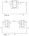
- a very stable fit of the display plate on the holding rail can be achieved if, as in the embodiment shown in FIG. 7, the holding tongues 5 are provided in the vicinity of the two side edges 18 of the display plate 3; one can arrange a single retaining tongue on each side edge 18 or, as shown in FIG. 7, one each Pair of holding tongues 5, whereby a particularly secure fixation of the display plate on the holding rail can be achieved, which can withstand even stronger impacts.
- FIGS. 1 to 4 There are a number of possibilities for the design of the holding rail which is provided in the device according to the invention. Which training is favorable in each case depends on the conditions present on the relevant storage container, storage rack, shop furniture or the like.
- To form the rear groove side surface gives the advantage that the holding rail a can have a very simple shape, and on the other hand the further advantage that a stepless sliding of the retaining tongues into the groove can be achieved when attaching the display plate.
- the rear leg 20 of the holding rail 4 is wider than the front leg 21 of this holding rail 4 and projects downward beyond the inlet 8 of the groove 6. You can so when attaching the display plate this or those provided on it Place the retaining tongues on the part of the rear leg of the retaining rail located outside the entrance of the groove and push the retaining tongues into the groove without requiring special care.
- both the front leg 21 and the rear leg 20 essentially end at the entrance 8 of the groove 6, and the edge of the rear leg 20 with a bevel 19 is to facilitate the insertion of the retaining tongues Mistake.
- the holding rails can be attached to the relevant storage container, storage rack, shop furniture or the like in various ways, e.g. by means of screws, rivets or even by gluing.
- an elastic intermediate layer 22 is inserted between the holding rail 4 and the wall of a storage container 2, one side of which is glued to the surface 24 of the storage container 2 and the other side of which is glued to the holding rail 4 is; so even small unevenness of the surface 24 is not disadvantageous.
- a covering rib 23 provided on the holding rail 4 protects the elastic intermediate layer 22 upwards.
- the holding rail can also simply be formed from sheet metal or from flat plastic material, the rail possibly also being formed by a part of a construction element serving primarily other purposes. Examples of such embodiments are shown in FIGS. 12 and 13.
- the holding rail 4 is formed by a strip consisting of sheet metal or flat plastic material, which is bent forward from the surface 24 to which the holding rail 4 is attached in the direction of arrow 26 and which projects with it an edge 25 abuts the surface 24 or is fastened there, and with its free edge 27 to form the undercut 10 of the front, undercut side surface 9 of the groove 6 is bent backwards.
- the holding rail 4 is through the edge region 29 of a cover consisting of sheet metal or flat plastic material 30 is formed, this edge region 29 protruding over the upper edge 28 of the surface 24 on which the holding rail 4 is arranged.
- a pressure tongue 17 is pivotally mounted on the rear side 15 of the display plate 3, on which a spring designed for example as a helical spring 16 acts, which in turn acts on the rear side 15 of the Display plate 3 is attached; when the holding tongues 5 are inserted into the groove of the holding rail, the pressing tongue 17 projects into the groove and comes to rest against the rear side surface 7 of the groove 6 due to the force of the spring 16.
- the holding tongues 5 are formed by at least one bar 31 which projects upwards at the upper edge of the display plate 3 and which carries a holding rib 12.
- a coil spring 16 is arranged below the attachment point of the bar 31 on the display plate 3 and engages on the holding rail 4 outside the input 8 of the groove 6, so that a moment of force is exerted on the display plate, which the display plate 3 in the direction of arrow 26 forward seeks to pan.
- a corresponding effect also results in the embodiment of a display plate 3 shown in FIGS.
- a below the attachment points of the strips 31 on the display plate 3 on this display plate attached double-arm leaf spring 14 serves, as explained above, to press the retaining tongues with the retaining ribs 12 into the undercut of the undercut groove side surface of the retaining rail provided in the device according to the invention, whereby the Location of this leaf spring 14 is below the attachment point of the retaining tongues on the display plate 3 and the points of attack of the ends of the spring 14 are below the retaining ribs 12, through the spring 14, a moment of force is generated which tries to pivot the display plate 3.
- a very stable fixation of leaf springs or pressure tongues on the display plate can be obtained by arranging at least one pocket 32 on the back of the display plate 3, as is provided in the embodiment shown in FIG. 14, and the leaf spring or pressure tongue with one Push the end into this pocket, improving the hold of the leaf spring or pressure tongue preferably locking or gluing can be provided.
- FIGS. 15 and 16 A variant of this is the embodiment shown in FIGS. 15 and 16, in which 3 groove strips 33 are formed on the rear side 15 of the display plate, between which a leaf spring 14 (or a retaining tongue) is inserted; it is additionally provided for secure fixation, a latching with stop lugs 34, which are integrally formed on the spring 14.
- a retaining tongue 5 integrally integrated with a leaf spring 14 in the form of an elongated strip which is folded approximately in its center 35 transversely to its longitudinal extent (arrow 36), one leg this structure is the spring 14 and the other leg is the retaining tongue 5; the retaining tongue 5 carries at its end 37 a retaining lug 11 which is designed in the form of a bend in the end 37 of this leg.
- This embodiment is particularly well suited for being attached to a display sign in accordance with the embodiments according to FIG. 14 or FIGS. 15 and 16.
- the width of the entrance 8 of the groove 6 is chosen to be as small as possible, i.e. that the thickness of the holding tongues 5 together with the holding lugs 11 or holding ribs 12 is only slightly smaller, e.g. by 1 to 2 mm, as the width of the entrance 8 of the groove 6.
- the width of the entrance 8 of the groove 6 is chosen to be as small as possible, i.e. that the thickness of the holding tongues 5 together with the holding lugs 11 or holding ribs 12 is only slightly smaller, e.g. by 1 to 2 mm, as the width of the entrance 8 of the groove 6.
Landscapes
- Physics & Mathematics (AREA)
- General Physics & Mathematics (AREA)
- Engineering & Computer Science (AREA)
- Theoretical Computer Science (AREA)
- Supports Or Holders For Household Use (AREA)
- Display Racks (AREA)
Applications Claiming Priority (2)
| Application Number | Priority Date | Filing Date | Title |
|---|---|---|---|
| AT2286/90 | 1990-11-13 | ||
| AT228690A AT394913B (de) | 1990-11-13 | 1990-11-13 | Einrichtung zur loesbaren befestigung von an lagerbehaeltern, lagerregalen, ladenmoebeln od. dgl. anzubringenden anzeigeschildern |
Publications (3)
| Publication Number | Publication Date |
|---|---|
| EP0486460A2 EP0486460A2 (de) | 1992-05-20 |
| EP0486460A3 EP0486460A3 (oth) | 1994-02-02 |
| EP0486460B1 true EP0486460B1 (de) | 1996-04-24 |
Family
ID=3531531
Family Applications (1)
| Application Number | Title | Priority Date | Filing Date |
|---|---|---|---|
| EP19910890257 Expired - Lifetime EP0486460B1 (de) | 1990-11-13 | 1991-10-25 | Einrichtung zur lösbaren Befestigung von an Lagerbehältern, Lagerregalen, Ladenmöbeln oder dergl. anzubringenden Anzeigeschildern |
Country Status (3)
| Country | Link |
|---|---|
| EP (1) | EP0486460B1 (oth) |
| AT (1) | AT394913B (oth) |
| DE (1) | DE59107719D1 (oth) |
Families Citing this family (6)
| Publication number | Priority date | Publication date | Assignee | Title |
|---|---|---|---|---|
| FR2706665B1 (fr) * | 1993-06-11 | 1995-09-08 | Fis | Dispositif pour la fixation d'un boîtier d'affichage électronique. |
| DE19534671A1 (de) * | 1995-09-19 | 1997-03-20 | Esselte Meto Int Gmbh | Vorrichtung zur Anzeige von Preis- und/oder Produktinformationen |
| FR2744825B1 (fr) * | 1996-02-14 | 1998-03-20 | Visioplast Sarl | Dispositif d'un moyen d'assemblage combinant un element de fixation et un porte-etiquettes |
| AT404888B (de) * | 1996-06-24 | 1999-03-25 | Tiedemann Roman | Steckrahmen für kennzeichnungsschilder |
| AT511894B1 (de) * | 2011-09-06 | 2013-06-15 | Arian Gesmbh | Montage von druckwerken in rahmenprofilen |
| AT14943U1 (de) * | 2014-12-10 | 2016-09-15 | Grasmann Josef | Halterung für ein Anzeigeelement |
Family Cites Families (6)
| Publication number | Priority date | Publication date | Assignee | Title |
|---|---|---|---|---|
| US1973413A (en) * | 1932-04-28 | 1934-09-11 | Mcdonnell Jay Philip | Display carrier and holder |
| FR1468720A (fr) * | 1965-06-16 | 1967-02-10 | élément profilé | |
| GB1218557A (en) * | 1967-11-02 | 1971-01-06 | Reginald Alfred George Smith | Improvements in or relating to signs |
| GB1473378A (en) * | 1975-10-28 | 1977-05-11 | Pilkington Tiles Ltd | Display apparatus |
| GB2191031B (en) * | 1986-05-22 | 1989-12-06 | Pendred Norman Co | Information ticket holder and assembly |
| US4919287A (en) * | 1988-06-03 | 1990-04-24 | Haskett Wayne J | Display unit for consumer products |
-
1990
- 1990-11-13 AT AT228690A patent/AT394913B/de not_active IP Right Cessation
-
1991
- 1991-10-25 EP EP19910890257 patent/EP0486460B1/de not_active Expired - Lifetime
- 1991-10-25 DE DE59107719T patent/DE59107719D1/de not_active Expired - Fee Related
Also Published As
| Publication number | Publication date |
|---|---|
| EP0486460A3 (oth) | 1994-02-02 |
| EP0486460A2 (de) | 1992-05-20 |
| AT394913B (de) | 1992-07-27 |
| ATA228690A (de) | 1991-12-15 |
| DE59107719D1 (de) | 1996-05-30 |
Similar Documents
| Publication | Publication Date | Title |
|---|---|---|
| DE60203982T2 (de) | Etikettenträger zur Befestigung an einem schmalkantigen Regal | |
| DE68914463T2 (de) | Etikettenhalter. | |
| DE602004005937T2 (de) | System zur Fixierung von Regalausstattungen | |
| DE2746118A1 (de) | Halter fuer informationstraeger in streifenform | |
| EP0224107A2 (de) | Vorrichtung zum Darbieten von Verkaufsartikeln | |
| DE2355646C2 (de) | Halter für das flexible Wischelement eines Fahrzeug-Scheibenwischers | |
| DE69804880T2 (de) | Automatisch verriegelbarer Schieber für Reissverschluss | |
| EP0486460B1 (de) | Einrichtung zur lösbaren Befestigung von an Lagerbehältern, Lagerregalen, Ladenmöbeln oder dergl. anzubringenden Anzeigeschildern | |
| EP0143299A2 (de) | Kanten- oder Eckbeschlag | |
| DE102007055301A1 (de) | Regaldisplay | |
| DE202009016050U1 (de) | Warentrennstab | |
| DD157153A5 (de) | Seitengriff fuer geschirre | |
| EP3050464B1 (de) | Möbelteil mit möbelteil-funktionselement | |
| DE3431062C2 (de) | Vorrichtung zum Anbringen einer Preisschild-Trägerschiene an Verkaufsregalen, -vitrinen oder dergleichen | |
| DE2431462A1 (de) | Aufbewahrungskasten fuer sortiert aufzubewahrende kleinteile | |
| DE2323860C3 (de) | Vorrichtung zum Führen von Schubladen | |
| DE60117624T2 (de) | System zum Fixieren von Etikettenhaltern und Regale | |
| EP0907943B1 (de) | Steckrahmen für kennzeichnungsschilder | |
| DE60317628T2 (de) | Posterrahmen für ein posterschild | |
| AT381634B (de) | Regalfach aus metallblech | |
| DE9300474U1 (de) | Kennzeichnungsschild | |
| DE8203745U1 (de) | Klammer | |
| EP0012993A1 (de) | Extrudiertes Preisschild aus Kunststoff | |
| DE202009002368U1 (de) | Behältnis für ein Geometriedreieck | |
| EP4261810A1 (de) | Werbe-halter sowie damit ausgestattetes verkaufsregal |
Legal Events
| Date | Code | Title | Description |
|---|---|---|---|
| PUAI | Public reference made under article 153(3) epc to a published international application that has entered the european phase |
Free format text: ORIGINAL CODE: 0009012 |
|
| AK | Designated contracting states |
Kind code of ref document: A2 Designated state(s): DE FR GB NL SE |
|
| PUAL | Search report despatched |
Free format text: ORIGINAL CODE: 0009013 |
|
| AK | Designated contracting states |
Kind code of ref document: A3 Designated state(s): DE FR GB NL SE |
|
| 17P | Request for examination filed |
Effective date: 19940718 |
|
| RAP1 | Party data changed (applicant data changed or rights of an application transferred) |
Owner name: ESSELTE METO INTERNATIONAL GMBH |
|
| RIN1 | Information on inventor provided before grant (corrected) |
Inventor name: TIEDEMANN, ROMAN |
|
| 17Q | First examination report despatched |
Effective date: 19950828 |
|
| GRAH | Despatch of communication of intention to grant a patent |
Free format text: ORIGINAL CODE: EPIDOS IGRA |
|
| GRAA | (expected) grant |
Free format text: ORIGINAL CODE: 0009210 |
|
| AK | Designated contracting states |
Kind code of ref document: B1 Designated state(s): DE FR GB NL SE |
|
| REF | Corresponds to: |
Ref document number: 59107719 Country of ref document: DE Date of ref document: 19960530 |
|
| ET | Fr: translation filed | ||
| GBT | Gb: translation of ep patent filed (gb section 77(6)(a)/1977) |
Effective date: 19960723 |
|
| PLBE | No opposition filed within time limit |
Free format text: ORIGINAL CODE: 0009261 |
|
| STAA | Information on the status of an ep patent application or granted ep patent |
Free format text: STATUS: NO OPPOSITION FILED WITHIN TIME LIMIT |
|
| 26N | No opposition filed | ||
| REG | Reference to a national code |
Ref country code: GB Ref legal event code: IF02 |
|
| PGFP | Annual fee paid to national office [announced via postgrant information from national office to epo] |
Ref country code: SE Payment date: 20021004 Year of fee payment: 12 |
|
| PGFP | Annual fee paid to national office [announced via postgrant information from national office to epo] |
Ref country code: FR Payment date: 20021008 Year of fee payment: 12 |
|
| PGFP | Annual fee paid to national office [announced via postgrant information from national office to epo] |
Ref country code: GB Payment date: 20021023 Year of fee payment: 12 |
|
| PGFP | Annual fee paid to national office [announced via postgrant information from national office to epo] |
Ref country code: NL Payment date: 20021031 Year of fee payment: 12 Ref country code: DE Payment date: 20021031 Year of fee payment: 12 |
|
| PG25 | Lapsed in a contracting state [announced via postgrant information from national office to epo] |
Ref country code: GB Free format text: LAPSE BECAUSE OF NON-PAYMENT OF DUE FEES Effective date: 20031025 |
|
| PG25 | Lapsed in a contracting state [announced via postgrant information from national office to epo] |
Ref country code: SE Free format text: LAPSE BECAUSE OF NON-PAYMENT OF DUE FEES Effective date: 20031026 |
|
| PG25 | Lapsed in a contracting state [announced via postgrant information from national office to epo] |
Ref country code: NL Free format text: LAPSE BECAUSE OF NON-PAYMENT OF DUE FEES Effective date: 20040501 Ref country code: DE Free format text: LAPSE BECAUSE OF NON-PAYMENT OF DUE FEES Effective date: 20040501 |
|
| EUG | Se: european patent has lapsed | ||
| GBPC | Gb: european patent ceased through non-payment of renewal fee |
Effective date: 20031025 |
|
| PG25 | Lapsed in a contracting state [announced via postgrant information from national office to epo] |
Ref country code: FR Free format text: LAPSE BECAUSE OF NON-PAYMENT OF DUE FEES Effective date: 20040630 |
|
| NLV4 | Nl: lapsed or anulled due to non-payment of the annual fee |
Effective date: 20040501 |
|
| REG | Reference to a national code |
Ref country code: FR Ref legal event code: ST |