EP0485843A1 - Vorrichtung zum Steuern des Öffnens/Schliessens einer Form - Google Patents
Vorrichtung zum Steuern des Öffnens/Schliessens einer Form Download PDFInfo
- Publication number
- EP0485843A1 EP0485843A1 EP91118739A EP91118739A EP0485843A1 EP 0485843 A1 EP0485843 A1 EP 0485843A1 EP 91118739 A EP91118739 A EP 91118739A EP 91118739 A EP91118739 A EP 91118739A EP 0485843 A1 EP0485843 A1 EP 0485843A1
- Authority
- EP
- European Patent Office
- Prior art keywords
- oil
- switching
- differential
- instruction signal
- capacity pump
- Prior art date
- Legal status (The legal status is an assumption and is not a legal conclusion. Google has not performed a legal analysis and makes no representation as to the accuracy of the status listed.)
- Granted
Links
- 238000006073 displacement reaction Methods 0.000 claims abstract description 14
- 239000002184 metal Substances 0.000 claims description 8
- 230000010354 integration Effects 0.000 claims description 2
- 230000007935 neutral effect Effects 0.000 description 6
- 238000001746 injection moulding Methods 0.000 description 3
- 230000001133 acceleration Effects 0.000 description 2
- 230000001276 controlling effect Effects 0.000 description 2
- 239000011347 resin Substances 0.000 description 2
- 229920005989 resin Polymers 0.000 description 2
- 101100452377 Arabidopsis thaliana IKU1 gene Proteins 0.000 description 1
- 101100452378 Arabidopsis thaliana IKU2 gene Proteins 0.000 description 1
- 238000010438 heat treatment Methods 0.000 description 1
- 238000002347 injection Methods 0.000 description 1
- 239000007924 injection Substances 0.000 description 1
- 238000000465 moulding Methods 0.000 description 1
- 230000001105 regulatory effect Effects 0.000 description 1
- 230000035939 shock Effects 0.000 description 1
Images


Classifications
-
- G—PHYSICS
- G05—CONTROLLING; REGULATING
- G05D—SYSTEMS FOR CONTROLLING OR REGULATING NON-ELECTRIC VARIABLES
- G05D3/00—Control of position or direction
- G05D3/12—Control of position or direction using feedback
- G05D3/14—Control of position or direction using feedback using an analogue comparing device
-
- B—PERFORMING OPERATIONS; TRANSPORTING
- B29—WORKING OF PLASTICS; WORKING OF SUBSTANCES IN A PLASTIC STATE IN GENERAL
- B29C—SHAPING OR JOINING OF PLASTICS; SHAPING OF MATERIAL IN A PLASTIC STATE, NOT OTHERWISE PROVIDED FOR; AFTER-TREATMENT OF THE SHAPED PRODUCTS, e.g. REPAIRING
- B29C45/00—Injection moulding, i.e. forcing the required volume of moulding material through a nozzle into a closed mould; Apparatus therefor
- B29C45/17—Component parts, details or accessories; Auxiliary operations
- B29C45/64—Mould opening, closing or clamping devices
- B29C45/67—Mould opening, closing or clamping devices hydraulic
-
- B—PERFORMING OPERATIONS; TRANSPORTING
- B29—WORKING OF PLASTICS; WORKING OF SUBSTANCES IN A PLASTIC STATE IN GENERAL
- B29C—SHAPING OR JOINING OF PLASTICS; SHAPING OF MATERIAL IN A PLASTIC STATE, NOT OTHERWISE PROVIDED FOR; AFTER-TREATMENT OF THE SHAPED PRODUCTS, e.g. REPAIRING
- B29C45/00—Injection moulding, i.e. forcing the required volume of moulding material through a nozzle into a closed mould; Apparatus therefor
- B29C45/17—Component parts, details or accessories; Auxiliary operations
- B29C45/76—Measuring, controlling or regulating
- B29C45/82—Hydraulic or pneumatic circuits
Definitions
- the present invention relates to a mold opening/closing control apparatus for an injection molding machine.
- a conventional injection molding machine resin which is heated in a heating cylinder and fluidized is injected into a mold at a high pressure, cooled therein so as to solidify or harden, and then the mold is opened and a molded product is removed.
- the injection molding machine has a mold clamping apparatus by means of which a mold is opened or closed and mold clamping is performed so that molten resin will not leak during the time of injection.
- a toggle type mold clamping apparatus in which a force generated by a hydraulic cylinder or a motor is amplified by a combination of links of toggle joints, and thus a large mold clamping force can be obtained
- a straight hydraulic type mold clamping apparatus in which a clamping force is directly generated by oil supplied to a mold clamping cylinder.
- a mold clamping cylinder and a mold opening/closing cylinder are disposed in the straight hydraulic type mold clamping apparatus. From the necessity of improving molding efficiency, mold opening/closing is performed at a high speed in a mold opening/closing cylinder. However, when mold closing is performed at a high speed, a movable metal mold could strike a fixed metal mold due to the inertial force of the movable platen, the movable metal mold or the like when the mold closing is terminated. When mold opening is performed at a high speed, a movable platen could strike a mold clamping cylinder by an inertial force similar to that described above. Accordingly, position control for a mold opening/closing cylinder is performed by a hydraulic control valve.
- an electromagnetic change-over valve for selectively supplying oil to either of the oil chambers of the mold opening/closing cylinder is disposed.
- a variable capacity pump is connected to one of the oil chambers of the electromagnetic selecting valve, and an electromagnetic proportional flow-rate control valve is connected to the other oil chamber.
- a maximum discharge amount of the variable capacity pump can be determined as described below. That is, the setting of a system pressure determines the pressure area of the mold opening/closing cylinder. Therefore, a maximum discharge amount of the variable capacity pump can be determined by a product of the abovementioned pressure area and a required maximum speed.
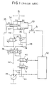
- Fig. 1 is a view showing a mold opening/closing control apparatus in which a differential circuit is used.
- reference numeral 31 denotes a cylinder in which a mold clamping cylinder and a mold opening/closing cylinder are made in one piece (hereinafter referred to as a mold clamping cylinder).
- a piston 32 is slidably disposed inside the cylinder.
- a large-diameter rod 33 and a small-diameter rod 34 are projected and formed on both sides of the piston 32.
- the large-diameter rod 33 is connected to a movable metal mold via a movable platen (not shown).
- the piston 32 reciprocates by the operation of the mold clamping cylinder 31, and mold opening/closing and mold clamping are performed
- An oil chamber 35 is formed in the end surface of the small-diameter rod 34 of the piston 32. Oil is supplied to the oil chamber 35 in a case where the movable platen is moved to a fixed platen at the time of closing the mold.
- An oil chamber 36 is formed in the large-diameter rod 33 of the piston 32. Oil is supplied to the oil chamber 36 in order to separate the movable platen from the fixed platen at the time of opening the mold.
- an oil chamber 37 for clamping the mold is formed in the small-diameter rod 34 of the piston 32 and also in the end surface of the piston 32.
- Reference numeral 38 denotes an electromagnetic change-over valve by means of which switching is performed by the actuation of solenoids a and b.
- the ports of the electromagnetic change-over valve 38 are individually connected to the oil chambers 35 and 36 inside the mold clamping cylinder 31, a variable capacity pump 39, an electromagnetic change-over valve 45, and an electromagnetic proportional control valve 40.
- the electromagnetic change-over valve 38 goes into position I if the solenoid a is driven and into position II if the solenoid b is driven.
- Position N is a neutral position.
- Reference numeral 39 denotes a variable capacity pump, in which the inclined rotational angle of a swash plate is changed by an instructed signal, whose amount of discharge is changed in proportion to the signal.
- Reference numeral 40 denotes an electromagnetic proportional flow-rate control valve which is electrically controlled by the solenoid a and by means of which a flow rate is proportionally controlled by an electrical signal.
- the electromagnetic proportional flow-rate control valve 40 constitutes a meter-out circuit by which control is made possible by the oil chamber 36.
- Reference numeral 41 denotes an electromagnetic change-over valve which goes to positions I and II by the actuation of the solenoid a.
- the electromagnetic proportional flow-rate control valve 40 is connected to an oil tank 44.
- an oil path 42 is connected with the electromagnetic proportional flow-rate control valve 40 through an oil path 43.
- the electromagnetic change-over valve 45 goes into positions I and II by the actuation of the solenoid a.
- the electromagnetic change-over valve 45 is made to go into position II at the time of opening and closing the mold. During that time, oil is taken into or discharged from between the oil chamber 37 and an oil tank 49 through a prefill valve 47 having pilot check.
- the electromagnetic change-over valve 45 is made to go into position II at the time of closing the mold, and oil is supplied to the oil chamber 37 for clamping the mold through the electromagnetic change-over valve 38.
- the above-described electromagnetic change-over valve 38, 41, and 45 are constructed only so as to be switched, and their resistance to passage is small.
- the mold clamping cylinder 31 has the large-diameter rod 33 and the small-diameter rod 34 on both sides of the piston 32, as described above.
- the two of them constitute oil chambers 35, 36, and 37.
- pressure area A3 is a value sufficient to generate a mold clamping force
- pressure area A2 is a value sufficient to generate a mold releasing force.
- To move the mold an oil pressure is applied to pressure areas A1 and A2.
- the pressure area A1 is made half of the pressure area A2, and a differential circuit is also used at the time of opening the mold.
- the electromagnetic change-over valve 38 is made to go into position II, the prefill electromagnetic change-over valve 45 is made to go into position II, and the electromagnetic change-over valve 41 is made to go into position I.
- oil discharged from the variable capacity pump 39 is supplied to the oil chamber 36, whereas the oil in the oil chamber 35 is released to an oil tank 44 via the electromagnetic change-over valve 38, the electromagnetic proportional flow-rate control valve 40, and the electromagnetic change-over valve 41.
- the prefill valve 47 having pilot check Since the pressure in an oil path 48 is high, the prefill valve 47 having pilot check is opened due to a pilot pressure received. The oil inside the oil chamber 37 is released to the oil tank 49 through the prefill valve 47 having pilot check.
- the electromagnetic change-over valves 38, 41, and 45 are made to go into position II.
- the electromagnetic proportional flow-rate control valve 40 is placed in a fully open state.
- the oil inside the oil chamber 35 is supplied to the oil path 42 through the electromagnetic change-over valve 38, the electromagnetic proportional flow-rate control valve 40, and the electromagnetic change-over valve 41, and supplied to the oil chamber 36 again via the electromagnetic change-over valve 38.
- a differential circuit operated by pressure areas A1 and A2 is formed.
- the piston 32 moves in the leftward direction in the figure, and a maximum speed for opening the mold can be obtained.
- the present invention has been devised to solve the above-described problems. It is accordingly an object of the present invention to provide a mold opening/closing control apparatus in which switching to a differential circuit while a piston is being moved can be performed smoothly.
- a hydraulic circuit in which a meter-in circuit and a differential circuit are combined, is connected to a mold opening/closing cylinder, and oil is supplied from a variable capacity pump.
- the mold opening/closing cylinder is operated.
- Speed instruction signals are integrated and made to be a position instruction signal.
- a positional deviation is determined from the position instruction signal and an actual displacement of the mold opening/closing cylinder.
- a flow-rate instruction signal is set by the positional deviation.
- a differential switching determining section when a differential switching determining section receives the above positional deviation, it compares the positional deviation with a reference value and determines whether differential switching should be performed.
- a differential change-over valve is connected to the differential switching determining section. When it receives a signal from the differential switching determining section, the meter-in circuit and the differential circuit are selected.
- a gain switching section is connected to the differential switching determining section. It switches between a gain for the meter-in circuit and a gain for the differential circuit in response to the reception of the positional deviation and a signal from the differential switching determining section. Therefore, a minimum variable capacity pump can be used, and a smooth switching between the meter-in circuit and the differential circuit can be made possible. Therefore, smooth acceleration/deceleration can be made possible.
- a fixed capacity pump can be connected to the variable capacity pump.
- it because it has an un-load and on-load determining section, it receives a flow-rate instruction signal from the gain switching section and compares it with a reference value to determine whether switching between un-loading and on-loading should be performed so that the switching will be performed. Therefore, a flow-rate instruction signal of a variable capacity pump can be made small, and the variable capacity pump can be further miniaturized.
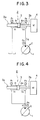
- Fig. 2 is a schematic view showing a mold opening/colsing control apparatus of an embodiment of the present invention.
- Fig. 3 is a view showing a meter-in circuit.
- Fig. 4 is a view showing a differential circuit.
- reference numeral 1 denotes a variable capacity pump
- reference numeral 2 denotes a mold opening/closing cylinder to which oil from the variable capacity pump 1 is supplied
- reference numeral 3 denotes a piston of the mold opening/closing cylinder 2
- reference numeral 4 denotes a movable platen operated by the mold opening/closing cylinder 2.
- the mold opening/closing cylinder 2 is disposed independently of an unillustrated mold clamping cylinder.
- a small-diameter rod 3b is attached to the movable platen 4 of the piston 3; a large-diameter rod 3a is attached to a side opposite to the movable platen 4.
- a pressure area of the piston 3 on the large-diameter rod 3a is represented as A1 and that on the small-diameter rod 3b is represented as A2.
- the driving force of the mold opening/closing cylinder 2 required at the time of opening the mold is given by the product of the pressure area A2 and a discharge pressure P3 of the variable capacity pump 1.
- the velocity of the piston 3 is determined by dividing the discharge flow rate q of the variable capacity pump 1 by the pressure area A2.
- the differential circuit of Fig. 4 although the driving force of the mold opening/closing cylinder 2 is smaller than that of the meter-in circuit in Fig. 3 because a pressure area is equivalent to A2 - A1, the velocity of the piston 3 is higher.
- the driving force and velocity required for the mold opening/closing cylinder 2 are realized from the discharge pressure P s and the discharge flow rate q of the variable capacity pump 1 having a minimum amount of capacity.
- variable capacity pump 1 is connected to only one of the oil chambers of the piston 3 so that mold opening only is performed.
- An electromagnetic change-over valve (not shown) is disposed between the variable capacity pump 1 and the mold opening/closing cylinder 2. Oil from the variable capacity pump 1 is selectively supplied to one of the oil chambers on either side of the piston 3, so that mold opening/closing can be performed.
- reference numeral 1 denotes a variable capacity pump which is capable of changing the amount of oil discharged
- reference numeral 2 denotes a mold opening/closing cylinder, in which a piston 3 is slidably disposed.
- the piston 3 reciprocates by the operation of the mold opening/closing cylinder 2 to cause a metal mold to be opened/closed by using the movable platen 4.
- Reference numeral 60 denotes an electromagnetic change-over valve which can be switched by solenoids a and b; reference numeral 61 denotes an oil path on a supply side, connected between the discharge side of the variable capacity pump 1 and the electromagnetic change-over valve 60, through which oil discharged from the variable capacity pump 1 flows, reference numeral 62 denotes an oil path on a return side, connected between the electromagnetic change-over valve 60 and a differential change-over valve 5, through which oil recovered from the mold opening/closing cylinder 2 flows.
- Oil chambers 2a and 2b are formed on the surface of both ends of the piston 3, and are selectively connected to the oil path 61 on the supply side and the oil path 62 on the return side via the electromagnetic change-over valve 60.
- the electromagnetic change-over valve 60 is switched by the actuation of the solenoids a and b.
- the ports of the electromagnetic change-over valve 60 are individually connected to the oil chambers 2a and 2b, the variable capacity pump 1, and the differential change-over valve 5.
- the solenoid a is driven, the electromagnetic change-over valve 60 goes into position I; when the solenoid b is driven, the electromagnetic change-over valve 60 goes into position II.
- Position N is a neutral position.
- the differential change-over valve 5 comprises an electromagnetic change-over valve operated by the solenoid a. It goes into positions I and II in response to the reception of an electrical signal. At position I, with the oil path 61 on the supply side connected to the oil path 62 on the return side, a differential circuit is formed. At position II, with the oil path 62 on the return side connected to the oil tank 63, a meter-in circuit is formed.
- Reference numeral 6 denotes a swash plate whose inclination angle is changed on the basis of an instruction signal which changes the amount of discharge from the variable capacity pump 1.
- the piston 3 of the mold opening/closing cylinder 2 is connected to a displacement sensor 7, which detects the stroke of the movement of the piston 3 and sends a displacement signal x e to a subtracter 8.
- Reference numeral 11 denotes an integrator to which a velocity instruction signal dx er ef /dt is input.
- the piston 3 moves at a velocity of dx e /dt proportional to a velocity instruction signal dx er ef /dt, and it stops at a specified position with a high degree of precision. Therefore, a position instruction signal x er ef is generated by the integrator 11, the displacement signal x e is fed back to the position instruction signal x er ef , and a positional deviation x er ef - x e is determined.
- the positional deviation x er ef - x e is input to a differential switching determining section 12 and a gain switching section 13.
- a flow-rate instruction signal q re f from the variable capacity pump 1 can be obtained by multiplying the positional deviation x er ef - x e by pump gains PG1 and PG2 set by the gain switching section 13. Because the mold opening/closing control apparatus basically performs closed loop control based on the position of the piston 3, a high degree of accuracy in coming to a stop can be obtained, and the piston 3 can move at a velocity proportional to the velocity instruction signal dx er ef /dt.
- the flow-rate instruction signal q re f changes smoothly because of the setting of the pump gains PG1 and PG2, with the result that an increase at the time of acceleration or deceleration can be lowered.
- the differential switching determining section 12 is provided to select the meter-in circuit of Fig. 3 when the piston 3 moves at a low speed, and to select the differential circuit of Fig. 4 when the piston 3 moves at a high speed.
- the differential switching determing section 12 goes on or off by the positional deviation x er ef - x e , causing the differential change-over valve 5 to be switched into position I or II.
- the inventor has taken notice that the flow-rate instruction signal q re f is proportional to the positional deviation x er ef - x e and, further, that the velocity dx e /dt is statically proportional to the positional deviation x er ef - x e .
- differential switching is determined by the positional deviation x er ef - x e .
- the differential switching determining section 12 has hysteresis for the purpose of preventing switch hunting. If the differential circuit is selected as a result of determing differential switching, an instruction is provided to the differential change-over valve 5 and a hydraulic circuit is switched. At the same time, an instruction is also provided to the gain switch section 13. Switching is performed from the pump gain PG1 for the meter-in circuit to the pump gain PG2 for the differential circuit.
- the flow-rate instruction signal q re f for the positional deviation x er ef - x e is lowered.
- Fig. 5 is a view showing the relationship between the positional deviation and flow-rate instruction of the mold opening/closing control apparatus of the present invention.
- the differential circuit is turned on when the positional deviation x er ef - x e becomes the value of IKU1 and turned off when the positional deviation x er ef - x e becomes IKU2. As shown in Fig 5, the differential circuit is turned on when the variable capacity pump 1 is at a maximum of flow rate, thereby lowering the flow-rate instruction signal q re f .
- a velocity d xe /dt which can ultimately be obtained may be represented by a straight line shown in Fig. 5.
- a timing adjustment section 14 is disposed to perform at the same time the pump gains PG1 and PG2 are switched in the gain switching section 13. Timing adjustment is performed by allowing idle time.
- Reference numeral 15 denotes a subtracter for making minor feedback adjustment; and reference numeral 16 denotes an amplifier.
- variable capacity pump 1 has a function for outputting a discharge flow rate q corresponding to the flow-rate instruction signal q re f .
- the variable capacity pump 1 is combined with a fixed capacity pump, costs can be reduced more than when a large variable capacity pump 1 or a plurality of variable capacity pumps are used.
- variable capacity pump 1 and a fixed capacity pump are combined.
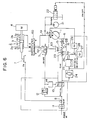
- Fig. 6 is a schematic view of a mold opening/closing control apparatus showing another embodiment of the present invention.
- reference numeral 1 denotes a variable capacity pump
- reference numeral 2 denotes a mold opening/closing cylinder, in which a piston 3 is slidably disposed.
- the piston 3 reciprocates by the operation of the mold opening/closing cylinder 2 to cause a metal mold to be opened/closed by using the movable platen 4.
- Reference numeral 60 denotes an electromagnetic change-over valve which can be switched by solenoids a and b; reference numeral 61 denotes an oil path on a supply side, connected between the discharge side of the variable capacity pump 1 and an electromagnetic change-over valve 60, through which oil discharged from the variable capacity pump 1 flows; reference numeral 62 denotes an oil path on a return side, connected between the electromagnetic change-over valve 60 and a differential change-over valve 5, through which oil recovered from the mold opening/closing cylinder 2 flows.
- Oil chambers 2a and 2b are formed on the surface of both ends of the piston 3.
- the oil chambers 2a and 2b are selectively connected to the oil path 61 on the supply side and the oil path 62 on the return side via the electromagnetic change-over valve 60.
- the electromagnetic change-over valve 60 is switched by the actuation of the solenoids a and b.
- the ports of the electromagnetic change-over valve 60 are individually connected to the oil chambers 2a and 2b, the variable capacity pump 1, and the differential change-over valve 5.
- Position N is a neutral position.
- the differential change-over valve 5 comprises an electromagnetic change-over valve operated by the solenoid a. It goes into positions I and II in response to the reception of an electrical signal. At position I, with the oil path 61 on the supply side connected to the oil path 62 on the return side, a differential circuit is formed. At position II, with the oil path 62 on the return side connected to the oil tank 63, a meter-in circuit is formed.
- Reference numeral 6 denotes a swash plate whose inclination angle is changed on the basis of an instruction signal which changes the amount of discharge from the variable capacity pump 1.
- the piston 3 of the mold opening/closing cylinder 2 is connected to a displacement sensor 7, which detects the stroke of the movement of the piston 3 and sends a displacement signal x e to a subtracter 8.
- Reference numeral 11 denotes an integrator to which a velocity instruction signal dx er ef /dt is input.
- the displacement signal x e is fed back to the position instruction signal x er ef , and a positional deviation x er ef -x e is determined.
- the positional deviation x er ef -x e is input to the differential switching determining section 12 and the gain switching section 13.
- a flow-rate instruction signal q re f from the variable capacity pump 1 can be obtained by multiplying the positional deviation x er ef - x e by pump gains PG1 and PG2 set by the gain switching section 13.
- the differential switching determining section 12 is provided to select the meter-in circuit of Fig. 3 when the piston 3 moves at a low speed, and to select the differential circuit of Fig. 4 when the piston 3 moves at a high speed.
- the differential switching determining section 12 goes on or off by the positional deviation x er ef - x e , causing the differential change-over valve 5 to be switched into positions I or II.
- differential circuit is selected as a result of determining differential switching by the differential switching determining section 12, an instruction is provided to the differential change-over valve 5 and a hydraulic circuit is switched. At the same time, an instruction is also provided to the gain switching section 13. Switching is performed from the pump gain PG1 for the meter-in circuit to the pump gain PG2 for the differential circuit. In order to make the differential change-over valve 5 opereate, a fixed amount of time is required. Therefore, a timing adjustment section 14 is disposed to perform at the same time the pump gains PG1 and PG2 are switched in the gain switching section 13. Timing adjustment is performed by allowing idle time.
- Reference numeral 15 denotes a subtracter for making minor feedback adjustment; and reference numeral 16 denotes an amplifier.
- a fixed capacity pump 21 and an un-load/on-load change-over valve 22 are added as a hydraulic circuit to the mold openin/closing control apparatus of Fig. 2.
- the flow-rate instruction signal q r ef obtained by the gain switching section 13 is sent to a subtracter 23 and un-load/on-load determining section 24.
- Fig. 7 is a view showing the relationship between a first flow-rate instruction signal to the un-load/on-load determining section and a second flow-rate instruction signal to the variable capacity pump.
- the un-load/on-load determining section 24 has hysteresis for the purpose of preventing switch hunting.
- the level of the flow-rate instruction signal q re f (a first flow-rate instruction signal) is raised and reaches a set value
- the un-load/on-load determining section 24 issues an on-load command to the un-load/on-load change-over valve 22, causing the fixed capacity pump 21 to be activated.
- the oil discharged from the fixed capacity pump 21 merges with the oil discharged from the variable capacity pump 1 and is sent to the oil chamber 2b.
- a value corresponding to the amount of oil discharged from the fixed capacity pump 21 is subtracted from the flow-rate instruction signal q re f of the variable capacity pump 1.
- the output of the un-load/on-load determining section 24 is sent out to a switch 26 via an idle time setter 25.
- the discharge amount q FO of the fixed capacity pump 21 is set by a setter 27, a compensation calculation for leakage in the fixed capacity pump 21 is performed by a subtracter 28, and the amount is sent to the subtracter 23 via the switch 26. That is, leakage proportional to the pressure P s on the discharge side occurs in the fixed capacity pump 21. Therefore, an actual discharge amount becomes q FO -K2 ⁇ P s , and the total flow-rate characteristics become uncontinuous at a switching point because operating conditions vary even if the value of a signal output from the un-load/on-load determining section 24 is adjusted.
- a command sent to the subtracter 23 is the actual discharge amount q FO -K2 ⁇ P s .
- the discharge amount q FO -K2 ⁇ P s is subtracted from the flow-rate instruction signal q re f from the gain switching section 13, and it is made to be a flow-rate instruction signal q re f '( a second flow-rate instruction signal) to the variable capacity pump 1.
- the switch 26 is turned on or off after a predetermined idle time has elapsed. What is more, an idle time t c1 is set when the switch 26 is switched off from on; an idle time t c2 is set when the switch 26 is switched on from off. In this way, switching from the variable capacity pump 1 to the fixed capacity pump 21, or vice versa, can be performed smoothly.
- Fig. 8 is a view showing the relationship between the positional deviation and the flow-rate instruction signal of the mold opening/closing control apparatus of another embodiment of the present invention.
- the difference between the first flow-rate instruction signal q re f and the second flow-rate instruction signal q re f ' is the discharge amount of the fixed capacity pump 21.
- pump gains PG1 and PG2 are switched, as described above, and the flow-rate instruction signal q re f is lowered according to the ratio of pressure areas.
- the level of the flow-rate instruction signal q re f is raised.
- reference values for determining differential switching by the differential switching determining section 12 and for determining un-load/on-load switching by the un-load/on-load determining section 24 are set.
- the above reference values are set so that the flow rate after switching from the differential circuit to the meter-in circuit is performed becomes smaller than the on-load set flow rate of the fixed capacity pump 21. They are also set so that the flow rate after switching from the meter-in circuit to the differential circuit is performed becomes larger than the un-load set flow rate of the fixed capacity pump 21.
Applications Claiming Priority (2)
| Application Number | Priority Date | Filing Date | Title |
|---|---|---|---|
| JP2299015A JP2788675B2 (ja) | 1990-11-06 | 1990-11-06 | 型開閉制御装置 |
| JP299015/90 | 1990-11-06 |
Publications (2)
| Publication Number | Publication Date |
|---|---|
| EP0485843A1 true EP0485843A1 (de) | 1992-05-20 |
| EP0485843B1 EP0485843B1 (de) | 1995-06-07 |
Family
ID=17867126
Family Applications (1)
| Application Number | Title | Priority Date | Filing Date |
|---|---|---|---|
| EP91118739A Expired - Lifetime EP0485843B1 (de) | 1990-11-06 | 1991-11-04 | Vorrichtung zum Steuern des Öffnens/Schliessens einer Form |
Country Status (4)
| Country | Link |
|---|---|
| US (1) | US5219584A (de) |
| EP (1) | EP0485843B1 (de) |
| JP (1) | JP2788675B2 (de) |
| DE (1) | DE69110247T2 (de) |
Cited By (2)
| Publication number | Priority date | Publication date | Assignee | Title |
|---|---|---|---|---|
| EP2583812A3 (de) * | 2011-10-20 | 2014-07-02 | Hesta Blasformtechnik GmbH&Co. KG | Verfahren zum Betrieb einer Blasformmaschine |
| AT524160A1 (de) * | 2020-08-19 | 2022-03-15 | Engel Austria Gmbh | Hydraulische Antriebsvorrichtung für eine Formgebungsmaschine |
Families Citing this family (8)
| Publication number | Priority date | Publication date | Assignee | Title |
|---|---|---|---|---|
| JP3002811B2 (ja) * | 1995-10-20 | 2000-01-24 | 日精樹脂工業株式会社 | 射出成形機の制御方法及び装置 |
| KR100466753B1 (ko) * | 1997-04-16 | 2005-04-14 | 스미도모쥬기가이고교 가부시키가이샤 | 사판식가변용량펌프의제어장치 |
| US20030054977A1 (en) * | 1999-10-12 | 2003-03-20 | Cell Therapeutics, Inc. | Manufacture of polyglutamate-therapeutic agent conjugates |
| JP2002240116A (ja) * | 2001-02-19 | 2002-08-28 | Sato Tekkosho:Kk | 射出成形用の型締装置及び射出成形装置 |
| JP4293415B2 (ja) * | 2002-08-26 | 2009-07-08 | 三菱重工プラスチックテクノロジー株式会社 | 型締装置および型締装置における多軸型締同期制御方法 |
| JP4629746B2 (ja) * | 2008-02-26 | 2011-02-09 | 日精樹脂工業株式会社 | 型締装置の制御方法 |
| JP4629747B2 (ja) * | 2008-02-26 | 2011-02-09 | 日精樹脂工業株式会社 | 型締装置の制御方法 |
| US10882105B2 (en) * | 2016-12-22 | 2021-01-05 | Nissei Plastic Industrial Co., Ltd. | Control method and drive control apparatus of hydraulic injection molding machine |
Citations (7)
| Publication number | Priority date | Publication date | Assignee | Title |
|---|---|---|---|---|
| FR2354465A1 (fr) * | 1976-06-10 | 1978-01-06 | Sanyo Kiki Kk | Dispositif accelerateur pour verins a mouvement alternatif |
| EP0025987A1 (de) * | 1979-09-20 | 1981-04-01 | Bêché & Grohs GmbH | Verfahren zur Steuerung des Arbeitsablaufes einer druckmittelbeaufschlagten Arbeitsmaschine sowie druckmittelbeaufschlagte Arbeitsmaschine mit Druckmittelsteuerung |
| GB2133905A (en) * | 1980-06-30 | 1984-08-01 | Karlstad Mekaniska Ab | A hydraulically operable press for use in the production of wood-based boards |
| DE3537421A1 (de) * | 1985-10-21 | 1987-04-23 | Rexroth Mannesmann Gmbh | Kunststoffverarbeitungsmaschine mit hydraulischen antrieben |
| EP0284903A2 (de) * | 1987-04-01 | 1988-10-05 | Gebr. Schmidt Fabrik Fur Feinmechanik | Kolbenpresse |
| DE8713628U1 (de) * | 1987-10-10 | 1989-02-09 | Robert Bosch Gmbh, 7000 Stuttgart, De | |
| EP0403041A2 (de) * | 1989-06-14 | 1990-12-19 | MANNESMANN Aktiengesellschaft | Spritzgiessmaschine mit hydraulischen Verbrauchern |
Family Cites Families (3)
| Publication number | Priority date | Publication date | Assignee | Title |
|---|---|---|---|---|
| DE3844432C1 (de) * | 1988-12-31 | 1990-01-25 | Karl 7298 Lossburg De Hehl | |
| JP2804096B2 (ja) * | 1989-07-17 | 1998-09-24 | 住友重機械工業株式会社 | 型締装置における油圧回路 |
| US4992036A (en) * | 1990-01-31 | 1991-02-12 | Cincinnati Milacron Inc. | Mold clamping system |
-
1990
- 1990-11-06 JP JP2299015A patent/JP2788675B2/ja not_active Expired - Fee Related
-
1991
- 1991-08-29 US US07/751,962 patent/US5219584A/en not_active Expired - Lifetime
- 1991-11-04 DE DE69110247T patent/DE69110247T2/de not_active Expired - Fee Related
- 1991-11-04 EP EP91118739A patent/EP0485843B1/de not_active Expired - Lifetime
Patent Citations (7)
| Publication number | Priority date | Publication date | Assignee | Title |
|---|---|---|---|---|
| FR2354465A1 (fr) * | 1976-06-10 | 1978-01-06 | Sanyo Kiki Kk | Dispositif accelerateur pour verins a mouvement alternatif |
| EP0025987A1 (de) * | 1979-09-20 | 1981-04-01 | Bêché & Grohs GmbH | Verfahren zur Steuerung des Arbeitsablaufes einer druckmittelbeaufschlagten Arbeitsmaschine sowie druckmittelbeaufschlagte Arbeitsmaschine mit Druckmittelsteuerung |
| GB2133905A (en) * | 1980-06-30 | 1984-08-01 | Karlstad Mekaniska Ab | A hydraulically operable press for use in the production of wood-based boards |
| DE3537421A1 (de) * | 1985-10-21 | 1987-04-23 | Rexroth Mannesmann Gmbh | Kunststoffverarbeitungsmaschine mit hydraulischen antrieben |
| EP0284903A2 (de) * | 1987-04-01 | 1988-10-05 | Gebr. Schmidt Fabrik Fur Feinmechanik | Kolbenpresse |
| DE8713628U1 (de) * | 1987-10-10 | 1989-02-09 | Robert Bosch Gmbh, 7000 Stuttgart, De | |
| EP0403041A2 (de) * | 1989-06-14 | 1990-12-19 | MANNESMANN Aktiengesellschaft | Spritzgiessmaschine mit hydraulischen Verbrauchern |
Non-Patent Citations (5)
| Title |
|---|
| KUNSTSTOFFE. vol. 66, no. 2, February 1976, MÜNCHEN DE pages 59 - 65; & WALTER: 'Die Anwendung von Hydraulikelementen bei Spritzgiessmaschinen' * |
| PATENT ABSTRACTS OF JAPAN vol. 10, no. 265 (M-515)(2321) 10 September 1986 & JP-A-61 089 020 ( TOYO KIKAI KINZOKU K.K. ) 7 May 1986 * |
| PATENT ABSTRACTS OF JAPAN vol. 14, no. 23 (M-920)(3966) 17 January 1990 & JP-A-1 263 019 ( SUMITOMO HEAVY IND LTD ) 19 October 1989 * |
| PATENT ABSTRACTS OF JAPAN vol. 7, no. 120 (M-217)(1265) 25 May 1983 & JP-A-58 038 134 ( DAIKIN KOGYO K.K. ) 5 March 1983 * |
| PATENT ABSTRACTS OF JAPAN vol. 9, no. 303 (M-434)(2026) 30 November 1985 & JP-A-60 141 400 ( AMADA K.K. ) 26 July 1985 * |
Cited By (3)
| Publication number | Priority date | Publication date | Assignee | Title |
|---|---|---|---|---|
| EP2583812A3 (de) * | 2011-10-20 | 2014-07-02 | Hesta Blasformtechnik GmbH&Co. KG | Verfahren zum Betrieb einer Blasformmaschine |
| AT524160A1 (de) * | 2020-08-19 | 2022-03-15 | Engel Austria Gmbh | Hydraulische Antriebsvorrichtung für eine Formgebungsmaschine |
| AT524160B1 (de) * | 2020-08-19 | 2022-06-15 | Engel Austria Gmbh | Hydraulische Antriebsvorrichtung für eine Formgebungsmaschine |
Also Published As
| Publication number | Publication date |
|---|---|
| US5219584A (en) | 1993-06-15 |
| JPH04173209A (ja) | 1992-06-19 |
| DE69110247T2 (de) | 1995-10-19 |
| DE69110247D1 (de) | 1995-07-13 |
| JP2788675B2 (ja) | 1998-08-20 |
| EP0485843B1 (de) | 1995-06-07 |
Similar Documents
| Publication | Publication Date | Title |
|---|---|---|
| EP0041273B1 (de) | Druckregeleinrichtung für ein hydrostatisches Getriebe | |
| US5179836A (en) | Hydraulic system for a differential piston type cylinder | |
| EP0462589B1 (de) | Steuervorrichtung für einen lastdruckkompensierten, hydraulischen Antrieb | |
| US4699571A (en) | Control valve for a variable displacement pump | |
| EP0485843B1 (de) | Vorrichtung zum Steuern des Öffnens/Schliessens einer Form | |
| US5528911A (en) | Hydraulic control apparatus for a plurality of users | |
| US5165320A (en) | Fluid-controlled servo-arrangement | |
| EP0513360A1 (de) | Hydraulikkreislaufsystem | |
| EP0667452B1 (de) | Kapazitätsregelvorrichtung für hydraulische pumpe mit veränderlicher fördermenge | |
| JP3216815B2 (ja) | 圧力補償弁を有する油圧回路 | |
| JPH0639951B2 (ja) | 油圧回路の制御方法 | |
| EP0417657B1 (de) | Verfahren zur Steuerung eines hydraulischen Verbrauchers | |
| JPH0849264A (ja) | 掘削機の油圧制御装置 | |
| US4451893A (en) | Control method and control system for hydrostatic drive system | |
| JP3685287B2 (ja) | 可変容量型油圧ポンプの容量制御装置 | |
| JP3240265B2 (ja) | 型締装置の油圧制御方法 | |
| JP2941470B2 (ja) | 型開閉制御装置 | |
| JP3553651B2 (ja) | 可変容量型油圧ポンプの容量制御装置 | |
| JP2866159B2 (ja) | 油圧制御回路 | |
| JPS62177303A (ja) | 油圧アクチユエ−タの制御方法 | |
| JP2837173B2 (ja) | 制御弁装置 | |
| JPH0347717A (ja) | 型締装置における油圧回路 | |
| JPH05172111A (ja) | 圧力補償式油圧回路の可変油圧ポンプ容量制御装置 | |
| JP3036164B2 (ja) | 油圧装置 | |
| JPH04314505A (ja) | 型開閉制御装置 |
Legal Events
| Date | Code | Title | Description |
|---|---|---|---|
| PUAI | Public reference made under article 153(3) epc to a published international application that has entered the european phase |
Free format text: ORIGINAL CODE: 0009012 |
|
| AK | Designated contracting states |
Kind code of ref document: A1 Designated state(s): DE FR GB IT |
|
| 17P | Request for examination filed |
Effective date: 19920625 |
|
| 17Q | First examination report despatched |
Effective date: 19930916 |
|
| RAP1 | Party data changed (applicant data changed or rights of an application transferred) |
Owner name: SUMITOMO HEAVY INDUSTRIES, LTD. |
|
| GRAA | (expected) grant |
Free format text: ORIGINAL CODE: 0009210 |
|
| ITF | It: translation for a ep patent filed |
Owner name: BARZANO' E ZANARDO MILANO S.P.A. |
|
| AK | Designated contracting states |
Kind code of ref document: B1 Designated state(s): DE FR GB IT |
|
| REF | Corresponds to: |
Ref document number: 69110247 Country of ref document: DE Date of ref document: 19950713 |
|
| ET | Fr: translation filed | ||
| PLBE | No opposition filed within time limit |
Free format text: ORIGINAL CODE: 0009261 |
|
| STAA | Information on the status of an ep patent application or granted ep patent |
Free format text: STATUS: NO OPPOSITION FILED WITHIN TIME LIMIT |
|
| 26N | No opposition filed | ||
| REG | Reference to a national code |
Ref country code: GB Ref legal event code: IF02 |
|
| PGFP | Annual fee paid to national office [announced via postgrant information from national office to epo] |
Ref country code: GB Payment date: 20021030 Year of fee payment: 12 |
|
| PGFP | Annual fee paid to national office [announced via postgrant information from national office to epo] |
Ref country code: FR Payment date: 20021108 Year of fee payment: 12 |
|
| PG25 | Lapsed in a contracting state [announced via postgrant information from national office to epo] |
Ref country code: GB Free format text: LAPSE BECAUSE OF NON-PAYMENT OF DUE FEES Effective date: 20031104 |
|
| GBPC | Gb: european patent ceased through non-payment of renewal fee |
Effective date: 20031104 |
|
| PG25 | Lapsed in a contracting state [announced via postgrant information from national office to epo] |
Ref country code: FR Free format text: LAPSE BECAUSE OF NON-PAYMENT OF DUE FEES Effective date: 20040730 |
|
| REG | Reference to a national code |
Ref country code: FR Ref legal event code: ST |
|
| PGFP | Annual fee paid to national office [announced via postgrant information from national office to epo] |
Ref country code: DE Payment date: 20081103 Year of fee payment: 18 |
|
| PGFP | Annual fee paid to national office [announced via postgrant information from national office to epo] |
Ref country code: IT Payment date: 20081126 Year of fee payment: 18 |
|
| PG25 | Lapsed in a contracting state [announced via postgrant information from national office to epo] |
Ref country code: DE Free format text: LAPSE BECAUSE OF NON-PAYMENT OF DUE FEES Effective date: 20100601 |
|
| PG25 | Lapsed in a contracting state [announced via postgrant information from national office to epo] |
Ref country code: IT Free format text: LAPSE BECAUSE OF NON-PAYMENT OF DUE FEES Effective date: 20091104 |