EP0484704B1 - Substratheizen mit Niedervoltbogenentladung und variablem Magnetfeld - Google Patents
Substratheizen mit Niedervoltbogenentladung und variablem MagnetfeldInfo
- Publication number
- EP0484704B1 EP0484704B1 EP91117606A EP91117606A EP0484704B1 EP 0484704 B1 EP0484704 B1 EP 0484704B1 EP 91117606 A EP91117606 A EP 91117606A EP 91117606 A EP91117606 A EP 91117606A EP 0484704 B1 EP0484704 B1 EP 0484704B1
- Authority
- EP
- European Patent Office
- Prior art keywords
- heated
- substrate
- magnetic field
- heating
- chamber
- Prior art date
- Legal status (The legal status is an assumption and is not a legal conclusion. Google has not performed a legal analysis and makes no representation as to the accuracy of the status listed.)
- Expired - Lifetime
Links
- 238000010438 heat treatment Methods 0.000 title claims abstract description 67
- 239000000758 substrate Substances 0.000 title claims abstract description 42
- 238000010891 electric arc Methods 0.000 title claims abstract description 10
- 239000000463 material Substances 0.000 claims abstract description 48
- 238000000034 method Methods 0.000 claims description 22
- 239000011248 coating agent Substances 0.000 claims description 6
- 238000000576 coating method Methods 0.000 claims description 6
- 238000009826 distribution Methods 0.000 claims description 6
- 230000000694 effects Effects 0.000 claims 1
- 238000004519 manufacturing process Methods 0.000 claims 1
- 239000007789 gas Substances 0.000 description 9
- 238000010586 diagram Methods 0.000 description 6
- XKRFYHLGVUSROY-UHFFFAOYSA-N Argon Chemical compound [Ar] XKRFYHLGVUSROY-UHFFFAOYSA-N 0.000 description 4
- 229910052786 argon Inorganic materials 0.000 description 2
- 238000010894 electron beam technology Methods 0.000 description 2
- 229910052756 noble gas Inorganic materials 0.000 description 2
- 230000002159 abnormal effect Effects 0.000 description 1
- 238000007872 degassing Methods 0.000 description 1
- 230000001419 dependent effect Effects 0.000 description 1
- 238000010292 electrical insulation Methods 0.000 description 1
- 239000011796 hollow space material Substances 0.000 description 1
- 238000002844 melting Methods 0.000 description 1
- 230000008018 melting Effects 0.000 description 1
- 229910052751 metal Inorganic materials 0.000 description 1
- 239000002184 metal Substances 0.000 description 1
- 150000002739 metals Chemical class 0.000 description 1
- 230000002093 peripheral effect Effects 0.000 description 1
- 230000005855 radiation Effects 0.000 description 1
- 238000005245 sintering Methods 0.000 description 1
- 238000005476 soldering Methods 0.000 description 1
Images

Classifications
-
- H—ELECTRICITY
- H01—ELECTRIC ELEMENTS
- H01J—ELECTRIC DISCHARGE TUBES OR DISCHARGE LAMPS
- H01J37/00—Discharge tubes with provision for introducing objects or material to be exposed to the discharge, e.g. for the purpose of examination or processing thereof
- H01J37/32—Gas-filled discharge tubes
- H01J37/32009—Arrangements for generation of plasma specially adapted for examination or treatment of objects, e.g. plasma sources
- H01J37/32055—Arc discharge
-
- H—ELECTRICITY
- H05—ELECTRIC TECHNIQUES NOT OTHERWISE PROVIDED FOR
- H05B—ELECTRIC HEATING; ELECTRIC LIGHT SOURCES NOT OTHERWISE PROVIDED FOR; CIRCUIT ARRANGEMENTS FOR ELECTRIC LIGHT SOURCES, IN GENERAL
- H05B7/00—Heating by electric discharge
-
- C—CHEMISTRY; METALLURGY
- C23—COATING METALLIC MATERIAL; COATING MATERIAL WITH METALLIC MATERIAL; CHEMICAL SURFACE TREATMENT; DIFFUSION TREATMENT OF METALLIC MATERIAL; COATING BY VACUUM EVAPORATION, BY SPUTTERING, BY ION IMPLANTATION OR BY CHEMICAL VAPOUR DEPOSITION, IN GENERAL; INHIBITING CORROSION OF METALLIC MATERIAL OR INCRUSTATION IN GENERAL
- C23C—COATING METALLIC MATERIAL; COATING MATERIAL WITH METALLIC MATERIAL; SURFACE TREATMENT OF METALLIC MATERIAL BY DIFFUSION INTO THE SURFACE, BY CHEMICAL CONVERSION OR SUBSTITUTION; COATING BY VACUUM EVAPORATION, BY SPUTTERING, BY ION IMPLANTATION OR BY CHEMICAL VAPOUR DEPOSITION, IN GENERAL
- C23C14/00—Coating by vacuum evaporation, by sputtering or by ion implantation of the coating forming material
- C23C14/22—Coating by vacuum evaporation, by sputtering or by ion implantation of the coating forming material characterised by the process of coating
- C23C14/54—Controlling or regulating the coating process
- C23C14/541—Heating or cooling of the substrates
-
- H—ELECTRICITY
- H01—ELECTRIC ELEMENTS
- H01J—ELECTRIC DISCHARGE TUBES OR DISCHARGE LAMPS
- H01J37/00—Discharge tubes with provision for introducing objects or material to be exposed to the discharge, e.g. for the purpose of examination or processing thereof
- H01J37/32—Gas-filled discharge tubes
- H01J37/32431—Constructional details of the reactor
- H01J37/32623—Mechanical discharge control means
-
- H—ELECTRICITY
- H01—ELECTRIC ELEMENTS
- H01J—ELECTRIC DISCHARGE TUBES OR DISCHARGE LAMPS
- H01J37/00—Discharge tubes with provision for introducing objects or material to be exposed to the discharge, e.g. for the purpose of examination or processing thereof
- H01J37/32—Gas-filled discharge tubes
- H01J37/32431—Constructional details of the reactor
- H01J37/3266—Magnetic control means
-
- H—ELECTRICITY
- H01—ELECTRIC ELEMENTS
- H01J—ELECTRIC DISCHARGE TUBES OR DISCHARGE LAMPS
- H01J2237/00—Discharge tubes exposing object to beam, e.g. for analysis treatment, etching, imaging
- H01J2237/32—Processing objects by plasma generation
- H01J2237/33—Processing objects by plasma generation characterised by the type of processing
- H01J2237/332—Coating
Definitions
- a special form of heating by electron bombardment is heating using a low-voltage arc;
- a low-voltage arc in the context of this description is to be understood as a gas discharge which burns between a hot cathode emitting electrons due to glow emission on the one hand and an anode on the other hand (it is irrelevant in this connection whether the cathode is kept at the emission temperature solely by the gas discharge or additionally is heated).
- a noble gas is admitted in the vicinity of the cathode, for example into the hollow space of a hollow cathode or into a special hot cathode chamber, which is connected to the vacuum recipient via an opening.
- the low-voltage arc is thus used to generate locally limited hot spots with large temperature differences from the surroundings.
- substrates by means of which, for example, longitudinally extended substrates, respectively. longitudinally extended substrate holders with several substrates are evenly heated.
- this object is achieved by means of a method according to the wording according to claim 1.
- the low-voltage arc discharge is magnetically bundled and at least one locally variable and / or displaceable magnetic field is maintained at least during the heating. It is either possible to keep the magnetic field stationary and to vary it by means of the current in the magnetic coil, or to move the magnetic coil locally, which means that the associated magnetic field is also shifted locally. It is essential that the distribution of the current density in the vacuum chamber is influenced, in order to shift the electrons in the gas discharge into different areas of the vacuum chamber, and thus to heat the substrate surface evenly. to accomplish the surface of the heating material. A higher electron density locally leads to a stronger heating of the corresponding substrate area. By pushing the electrons back and forth through the variation of the magnetic field, a uniform heating of the substrate can be achieved.
- At least two partially overlapping magnetic fields are maintained, which are operated alternately stronger and weaker.
- stronger or weaker heating can alternately be effected along the substrate surface.
- the electrons are always pushed into the area where the magnetic field is weaker. Accordingly, the heating of the substrate is greater in the area where the magnetic field is weakly maintained.
- the at least one or the two magnetic fields mentioned is parallel along the surface of the heating material, respectively. of the substrate varies locally and / or maintained displaceably.
- a device for the uniform heating of heating material resp. proposed a substrate to be coated, which comprises a vacuum chamber for receiving the heating material or substrate, and a cathode chamber connected to the vacuum chamber with a hot cathode located therein, and with at least one magnet coil arranged in the region of the vacuum chamber, which can be operated in this way, that a locally variable and / or displaceable magnetic field can be maintained in the vacuum chamber at least during heating.
- At least two magnetic coils are provided in the region of the vacuum chamber, which are arranged at a distance from one another in such a way that in the vacuum chamber two essentially to the heating material or. Coaxial magnetic fields arise with the substrates.
- Fig. 1 means a bell-shaped vacuum recipient in which the heating material 3 is carried on a holder 2.
- the holder is fastened to the base plate 5 of the recipient by means of electrical insulation 4 and is electrically connected to the positive pole of a supply device 7 via a vacuum-tight feedthrough 6.
- a hot cathode chamber 8 is attached to the upper part of the recipient and is connected to the interior of the recipient 1 via an opening 9.
- the hot cathode 12 is accommodated, which, as indicated in the drawing, can be a wire heated by current passage; however, it can also be designed in the form of a heated or self-heating hollow cathode.
- a control valve 13 is provided for the admission of gases into the hot cathode chamber.
- Two magnetic coils 14a and 14b generate magnetic fields 16 coaxial with the recipient 1. If one follows the central field line starting from the opening 9, the magnetic field 16 initially becomes stronger and reaches a maximum intensity on the central plane of the magnetic coil 14a. When further removed from the opening 9, the magnetic field initially weakens, then becomes stronger again and reaches a second maximum of the intensity on the central plane of the magnetic coil 14b. The strength of the magnetic fields 16 is now dependent on the current strength with which the two magnetic coils 14a and. 14b are operated. In the device shown in Fig. 1 it is provided that the two solenoids 14a and 14b can be operated with different currents.
- the recipient and the hot cathode chamber 8 connected to it are pumped out of air with the aid of a high vacuum pump on the pump nozzle 15 until a pressure of less than about 0.01 P is reached.
- the valve 13 then lets in as much gas, e.g. the noble gas argon flow in, so that an argon pressure between 0.1 and 1 P is established in the recipient.
- the hot cathode 12 is then heated and the supply device 7 is switched on.
- the latter generates an electrical voltage of e.g. 100 V.
- the electrons entering the recipient 1 through the opening 9 follow the field lines of the magnetic fields with sufficient field strengths (e.g. 0.01 T).
- the magnetic fields make it easier for the electrons to move parallel to the axis than perpendicular to the axis.
- the electron current is distributed over the whole, as an anode-connected holder 2.
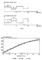
- FIG. 2 now shows in diagram form how the two magnetic coils 14a and 14b are to be operated, for example.
- the upper diagram in FIG. 2 relates to the current intensity in the upper coil, while the lower diagram relates to the current intensity in the lower coil 14b.
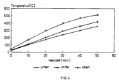
- FIGS. 3 and 4 The influence is shown graphically in FIGS. 3 and 4 when the magnetic fields are operated differently. It clearly shows that with a uniform magnetic field according to FIG. 4, the lower and upper area of the coating system, respectively. is heated less in the recipient than the central area. With differently operated magnetic fields according to FIG. 3, the heating is uniform and corresponds approximately to the mean value of the heating when the magnetic field is operated without variation.
- the diagram in FIG. 4 clearly shows that not only is the presence of two magnetic fields responsible for uniform heating of the heating material, but also, as shown in FIG. 3 by operating the magnetic fields differently, as described for example with reference to FIG. 2.
- the device shown in FIG. 1 naturally only includes one example.
- it is also possible to arrange only one magnetic coil which, however, can be moved locally.
- It is also possible to arrange a plurality of magnetic coils it being possible, for example, to additionally arrange a magnetic coil in the region of the hot cathode chamber 8.
- a magnetic coil is arranged in the region of the hot cathode chamber 8
- it is possible to generate different magnetic fields in the recipient by means of different current intensities I in the magnet coils arranged in this way.
- Essential to the invention is in any case only that in the coating chamber, respectively. at least one variable magnetic field is generated in the recipient or the vacuum chamber so as to locally change the current density during the heating process in the chamber.
Landscapes
- Engineering & Computer Science (AREA)
- Chemical & Material Sciences (AREA)
- Physics & Mathematics (AREA)
- Plasma & Fusion (AREA)
- Analytical Chemistry (AREA)
- Materials Engineering (AREA)
- Chemical Kinetics & Catalysis (AREA)
- Mechanical Engineering (AREA)
- Metallurgy (AREA)
- Organic Chemistry (AREA)
- Physical Vapour Deposition (AREA)
- Chemical Vapour Deposition (AREA)
- Plasma Technology (AREA)
- Discharge Heating (AREA)
Applications Claiming Priority (2)
| Application Number | Priority Date | Filing Date | Title |
|---|---|---|---|
| DE4035131 | 1990-11-05 | ||
| DE4035131A DE4035131C2 (de) | 1990-11-05 | 1990-11-05 | Verfahren und Vorrichtung zum gleichmäßigen Erwärmen von Heizgut, insbes. von zu beschichtenden Substraten, in einer Vakuumkammer |
Publications (2)
| Publication Number | Publication Date |
|---|---|
| EP0484704A1 EP0484704A1 (de) | 1992-05-13 |
| EP0484704B1 true EP0484704B1 (de) | 1994-07-20 |
Family
ID=6417661
Family Applications (1)
| Application Number | Title | Priority Date | Filing Date |
|---|---|---|---|
| EP91117606A Expired - Lifetime EP0484704B1 (de) | 1990-11-05 | 1991-10-16 | Substratheizen mit Niedervoltbogenentladung und variablem Magnetfeld |
Country Status (6)
| Country | Link |
|---|---|
| EP (1) | EP0484704B1 (ja) |
| JP (1) | JP3302710B2 (ja) |
| KR (1) | KR100246490B1 (ja) |
| AT (1) | ATE108836T1 (ja) |
| DE (2) | DE4035131C2 (ja) |
| ES (1) | ES2056552T3 (ja) |
Families Citing this family (6)
| Publication number | Priority date | Publication date | Assignee | Title |
|---|---|---|---|---|
| CH687111A5 (de) * | 1992-05-26 | 1996-09-13 | Balzers Hochvakuum | Verfahren zum Erzeugen einer Niederspannungsentladung, Vakuumbehandlungsanlage hierfuer sowie Anwendung des Verfahrens. |
| DE4437269C1 (de) * | 1994-10-18 | 1996-02-22 | Balzers Hochvakuum | Verfahren zum Reinigen einer Werkstückoberfläche und seine Verwendung |
| DE19500262C1 (de) * | 1995-01-06 | 1995-09-28 | Metaplas Oberflaechenveredelun | Verfahren zur Plasmabehandlung von Werkstücken |
| DE19521548A1 (de) * | 1995-06-13 | 1996-12-19 | Ipsen Ind Int Gmbh | Verfahren und Vorrichtung zur Steuerung der elektrischen Stromdichte über einem Werkstück bei der Wärmebehandlung im Plasma |
| DE19725930C2 (de) * | 1997-06-16 | 2002-07-18 | Eberhard Moll Gmbh Dr | Verfahren und Anlage zum Behandeln von Substraten mittels Ionen aus einer Niedervoltbogenentladung |
| DE10018143C5 (de) * | 2000-04-12 | 2012-09-06 | Oerlikon Trading Ag, Trübbach | DLC-Schichtsystem sowie Verfahren und Vorrichtung zur Herstellung eines derartigen Schichtsystems |
Family Cites Families (6)
| Publication number | Priority date | Publication date | Assignee | Title |
|---|---|---|---|---|
| DE1175374B (de) * | 1960-01-04 | 1964-08-06 | Nat Res Dev | Lichtbogenbrenner |
| US3210454A (en) * | 1962-05-17 | 1965-10-05 | Alloyd Electronics Corp | High temperature apparatus |
| CH631743A5 (de) * | 1977-06-01 | 1982-08-31 | Balzers Hochvakuum | Verfahren zum aufdampfen von material in einer vakuumaufdampfanlage. |
| CH645137A5 (de) * | 1981-03-13 | 1984-09-14 | Balzers Hochvakuum | Verfahren und vorrichtung zum verdampfen von material unter vakuum. |
| CH658545A5 (de) * | 1982-09-10 | 1986-11-14 | Balzers Hochvakuum | Verfahren zum gleichmaessigen erwaermen von heizgut in einem vakuumrezipienten. |
| DE3829260A1 (de) * | 1988-08-29 | 1990-03-01 | Multi Arc Gmbh | Plasmabeschichtungskammer mit entfernbarem schutzschirm |
-
1990
- 1990-11-05 DE DE4035131A patent/DE4035131C2/de not_active Expired - Fee Related
-
1991
- 1991-10-16 DE DE59102249T patent/DE59102249D1/de not_active Expired - Lifetime
- 1991-10-16 EP EP91117606A patent/EP0484704B1/de not_active Expired - Lifetime
- 1991-10-16 ES ES91117606T patent/ES2056552T3/es not_active Expired - Lifetime
- 1991-10-16 AT AT91117606T patent/ATE108836T1/de not_active IP Right Cessation
- 1991-11-01 JP JP28800691A patent/JP3302710B2/ja not_active Expired - Lifetime
- 1991-11-04 KR KR1019910019533A patent/KR100246490B1/ko not_active IP Right Cessation
Also Published As
| Publication number | Publication date |
|---|---|
| JP3302710B2 (ja) | 2002-07-15 |
| KR920011295A (ko) | 1992-06-27 |
| JPH04289160A (ja) | 1992-10-14 |
| DE4035131C2 (de) | 1995-09-21 |
| DE4035131A1 (de) | 1992-05-07 |
| KR100246490B1 (ko) | 2000-04-01 |
| DE59102249D1 (de) | 1994-08-25 |
| ES2056552T3 (es) | 1994-10-01 |
| ATE108836T1 (de) | 1994-08-15 |
| EP0484704A1 (de) | 1992-05-13 |
Similar Documents
| Publication | Publication Date | Title |
|---|---|---|
| EP0275018B1 (de) | Verfahren und Vorrichtung zum Beschichten elektrisch leitender Gegenstände mittels Glimmentladung | |
| EP0463230B1 (de) | Vorrichtung zum Beschichten von Substraten | |
| DE3513014C2 (de) | Verfahren zur Behandlung der Oberfläche von Werkstücken | |
| EP2795657B1 (de) | Vorrichtung zum erzeugen eines hohlkathodenbogenentladungsplasmas | |
| EP0529259A1 (de) | Einrichtung zum Behandeln von Substraten | |
| EP0727508A1 (de) | Verfahren und Vorrichtung zur Behandlung von Substratoberflächen | |
| DE3615361C2 (de) | Vorrichtung zur Oberflächenbehandlung von Werkstücken | |
| EP1576641B1 (de) | Vacuumarcquelle mit magnetfelderzeugungseinrichtung | |
| EP0484704B1 (de) | Substratheizen mit Niedervoltbogenentladung und variablem Magnetfeld | |
| DE3330144C2 (de) | Verfahren zum gleichmässigen Erwärmen von Heizgut in einem Vakuumrezipienten | |
| DE10084452B3 (de) | Lichtbogenquelle mit rechteckiger Kathode und Verfahren zur Lenkung eines Lichtbogenflecks | |
| DE1565883B1 (de) | Vorrichtung zum Erhitzen eines Materials mittels Elektronen | |
| DE69020553T2 (de) | Elektrische Lichtbogenbehandlung von Teilchen. | |
| DE102008028166B4 (de) | Vorrichtung zur Erzeugung eines Plasma-Jets | |
| DE3837487A1 (de) | Verfahren und vorrichtung zum aetzen von substraten mit einer magnetfeldunterstuetzten niederdruck-entladung | |
| DE3614398A1 (de) | Anordnung zum behandeln von werkstuecken mit einer evakuierbaren kammer | |
| CH695807A5 (de) | Quelle für Vakuumbehandlungsprozess. | |
| DE19500262C1 (de) | Verfahren zur Plasmabehandlung von Werkstücken | |
| EP0791226B1 (de) | Vorrichtung zum beschichten von substraten mit einem materialdampf im unterdruck oder vakuum | |
| DE3406953C2 (de) | Verfahren zum Erwärmen von Heizgut in einem Vakuumrezipienten | |
| DE102004015231B4 (de) | Verfahren und Vorrichtung zum Behandeln von Substratoberflächen mittels Ladungsträgerbeschuss | |
| DE19627004C2 (de) | Strahlungsquelle sowie Glühkathode für den Einsatz in einer Strahlungsquelle | |
| DE3222327A1 (de) | Einrichtung zur vakuumbedampfung | |
| CH702969A2 (de) | Segmentierte Anode. | |
| DE10303428A1 (de) | Verfahren und Einrichtung zur plasmaaktivierten Schichtabscheidung durch Kathodenzerstäubung nach dem Magnetron-Prinzip |
Legal Events
| Date | Code | Title | Description |
|---|---|---|---|
| PUAI | Public reference made under article 153(3) epc to a published international application that has entered the european phase |
Free format text: ORIGINAL CODE: 0009012 |
|
| AK | Designated contracting states |
Kind code of ref document: A1 Designated state(s): AT CH DE ES FR GB IT LI SE |
|
| 17P | Request for examination filed |
Effective date: 19920423 |
|
| 17Q | First examination report despatched |
Effective date: 19931203 |
|
| GRAA | (expected) grant |
Free format text: ORIGINAL CODE: 0009210 |
|
| AK | Designated contracting states |
Kind code of ref document: B1 Designated state(s): AT CH DE ES FR GB IT LI SE |
|
| REF | Corresponds to: |
Ref document number: 108836 Country of ref document: AT Date of ref document: 19940815 Kind code of ref document: T |
|
| GBT | Gb: translation of ep patent filed (gb section 77(6)(a)/1977) |
Effective date: 19940726 |
|
| REF | Corresponds to: |
Ref document number: 59102249 Country of ref document: DE Date of ref document: 19940825 |
|
| ET | Fr: translation filed | ||
| ITF | It: translation for a ep patent filed | ||
| REG | Reference to a national code |
Ref country code: ES Ref legal event code: FG2A Ref document number: 2056552 Country of ref document: ES Kind code of ref document: T3 |
|
| EAL | Se: european patent in force in sweden |
Ref document number: 91117606.3 |
|
| PLBE | No opposition filed within time limit |
Free format text: ORIGINAL CODE: 0009261 |
|
| STAA | Information on the status of an ep patent application or granted ep patent |
Free format text: STATUS: NO OPPOSITION FILED WITHIN TIME LIMIT |
|
| 26N | No opposition filed | ||
| REG | Reference to a national code |
Ref country code: GB Ref legal event code: IF02 |
|
| PGFP | Annual fee paid to national office [announced via postgrant information from national office to epo] |
Ref country code: AT Payment date: 20051012 Year of fee payment: 15 |
|
| PG25 | Lapsed in a contracting state [announced via postgrant information from national office to epo] |
Ref country code: AT Free format text: LAPSE BECAUSE OF NON-PAYMENT OF DUE FEES Effective date: 20061016 |
|
| REG | Reference to a national code |
Ref country code: CH Ref legal event code: PFA Owner name: OC OERLIKON BALZERS AG Free format text: BALZERS AKTIENGESELLSCHAFT# #9496 BALZERS (LI) -TRANSFER TO- OC OERLIKON BALZERS AG#PATENTABTEILUNG POSTFACH 1000#9496 BALZERS (LI) |
|
| REG | Reference to a national code |
Ref country code: CH Ref legal event code: PUE Owner name: OERLIKON TRADING AG, TRUEBBACH Free format text: OC OERLIKON BALZERS AG#PATENTABTEILUNG POSTFACH 1000#9496 BALZERS (LI) -TRANSFER TO- OERLIKON TRADING AG, TRUEBBACH#HAUPTSTRASSE#9477 TRUEBBACH (CH) |
|
| REG | Reference to a national code |
Ref country code: FR Ref legal event code: CD |
|
| PGFP | Annual fee paid to national office [announced via postgrant information from national office to epo] |
Ref country code: FR Payment date: 20101020 Year of fee payment: 20 |
|
| PGFP | Annual fee paid to national office [announced via postgrant information from national office to epo] |
Ref country code: DE Payment date: 20101013 Year of fee payment: 20 |
|
| REG | Reference to a national code |
Ref country code: ES Ref legal event code: PC2A Owner name: OERLIKON TRADING AG,TRUBBACH Effective date: 20110309 |
|
| PGFP | Annual fee paid to national office [announced via postgrant information from national office to epo] |
Ref country code: GB Payment date: 20101013 Year of fee payment: 20 Ref country code: SE Payment date: 20101012 Year of fee payment: 20 Ref country code: IT Payment date: 20101020 Year of fee payment: 20 |
|
| PGFP | Annual fee paid to national office [announced via postgrant information from national office to epo] |
Ref country code: CH Payment date: 20110126 Year of fee payment: 20 |
|
| PGFP | Annual fee paid to national office [announced via postgrant information from national office to epo] |
Ref country code: ES Payment date: 20101122 Year of fee payment: 20 |
|
| REG | Reference to a national code |
Ref country code: DE Ref legal event code: R071 Ref document number: 59102249 Country of ref document: DE |
|
| REG | Reference to a national code |
Ref country code: DE Ref legal event code: R071 Ref document number: 59102249 Country of ref document: DE |
|
| REG | Reference to a national code |
Ref country code: CH Ref legal event code: PL |
|
| REG | Reference to a national code |
Ref country code: GB Ref legal event code: PE20 Expiry date: 20111015 |
|
| REG | Reference to a national code |
Ref country code: SE Ref legal event code: EUG |
|
| PG25 | Lapsed in a contracting state [announced via postgrant information from national office to epo] |
Ref country code: GB Free format text: LAPSE BECAUSE OF EXPIRATION OF PROTECTION Effective date: 20111015 |
|
| PG25 | Lapsed in a contracting state [announced via postgrant information from national office to epo] |
Ref country code: DE Free format text: LAPSE BECAUSE OF EXPIRATION OF PROTECTION Effective date: 20111017 |
|
| REG | Reference to a national code |
Ref country code: ES Ref legal event code: FD2A Effective date: 20140826 |
|
| PG25 | Lapsed in a contracting state [announced via postgrant information from national office to epo] |
Ref country code: ES Free format text: LAPSE BECAUSE OF EXPIRATION OF PROTECTION Effective date: 20111017 |