EP0481952B1 - Pièce soumise à l'usure remplaçable - Google Patents
Pièce soumise à l'usure remplaçable Download PDFInfo
- Publication number
- EP0481952B1 EP0481952B1 EP91890222A EP91890222A EP0481952B1 EP 0481952 B1 EP0481952 B1 EP 0481952B1 EP 91890222 A EP91890222 A EP 91890222A EP 91890222 A EP91890222 A EP 91890222A EP 0481952 B1 EP0481952 B1 EP 0481952B1
- Authority
- EP
- European Patent Office
- Prior art keywords
- wearing
- basic
- wear
- supporting
- supporting part
- Prior art date
- Legal status (The legal status is an assumption and is not a legal conclusion. Google has not performed a legal analysis and makes no representation as to the accuracy of the status listed.)
- Expired - Lifetime
Links
Images

Classifications
-
- B—PERFORMING OPERATIONS; TRANSPORTING
- B27—WORKING OR PRESERVING WOOD OR SIMILAR MATERIAL; NAILING OR STAPLING MACHINES IN GENERAL
- B27L—REMOVING BARK OR VESTIGES OF BRANCHES; SPLITTING WOOD; MANUFACTURE OF VENEER, WOODEN STICKS, WOOD SHAVINGS, WOOD FIBRES OR WOOD POWDER
- B27L11/00—Manufacture of wood shavings, chips, powder, or the like; Tools therefor
- B27L11/005—Tools therefor
Definitions
- the invention relates to an interchangeable wear part, in particular a wear plate or wear shoe, for protecting components against abrasive removal, in particular in machine-technical facilities, such as, for example, woodworking and wood crushing machines and the like, or for at least partially armoring on walls exposed to abrasion.
- a wear plate or wear shoe for protecting components against abrasive removal, in particular in machine-technical facilities, such as, for example, woodworking and wood crushing machines and the like, or for at least partially armoring on walls exposed to abrasion.
- Wear parts or armor and the like have the purpose of preventing abrasion of components or machine parts from material removal or keeping them as low as possible in order to increase the service life of such parts and / or operational safety.
- Wear elements are often used in machines in order to counteract a change in the geometric conditions by ablation, which can have a disruptive effect on the work functions.
- Armor can be easily made by often welding wear-resistant filler metal to the component or machine part.
- this has the disadvantage that distortion phenomena can occur due to the introduction of heat into the part, and a costly rework is usually required to smooth the surface.
- the invention has for its object to provide an interchangeable wear part of the type mentioned, which has high wear resistance and durability, has low risk of breakage and is easy to attach with high stability.
- This object is achieved in that the wearing part is formed from a base part made of tough material and a support part made of a material which has a high wear resistance, the base part and the support part being connected to one another in a flat manner and the base part having a fastening element by means of which the wear part is releasably attachable to the component.
- the wearing part 1 shown in Fig. 1 is a plate-shaped element provided with a fastener, which consists of a support part 3 made of wear-resistant tool steel (e.g. DIN work number 1.20 ⁇ 80 ⁇ ) and a base part 2 made of a weldable structural steel consists.
- the plate-shaped element was made of a composite material, for example Composite steel sheet worked out, this (s) from two material parts, which are metallically interconnected, existing plate or sheet with a thickness of 12 mm was produced by roll welding. A thermal treatment or hardening takes place with a view to the highest wear resistance and hardness of the support part 3.
- the attachment of a fastening element 4 was carried out by arc welding or butt welding to form a weld or weld bead 5.
- the fastening element 4 in the area of the connection 5 to the base part 2 can also be enlarged or have a larger diameter. This is preferably advantageous if larger bending stresses also occur.
- the thickness of the base part 2 is equal to or greater than the thickness a of the support part 3.
- the support part 3 can also be made of hard metal and cannot be removed from the base part 2 by soldering or the like be connected.
- the support part 3 can be created by welding plating the base part 2.
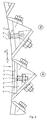
- Fig. 2 shows a wearing part 1 according to the invention and a conventional part 1 ', installed in a rotating ring of a cutting device. This ring equipped with knife 7 rotates in the direction R, with the cutting wooden parts being moved in the opposite direction.
- the wear part 1 shown in area A according to the invention shows a uniform removal to a small extent from the surface 32 of the support part when producing wood chips 3.
- a conventional wearing part 1 ' is shown, which has a threaded bore and is fastened to the ring part by means of a screw 4'.
- a screw 4' In the case of abrasive stress, there is an increased removal of the materials in the area of the screw breakthrough and, furthermore, local scouring 9 of the wearing part 1 '.
- the screw connection may also be loosened and / or knocked out, in particular due to an unsteady load under high stress, which means that it is often necessary to retighten the screws or to replace the wearing parts.
Landscapes
- Life Sciences & Earth Sciences (AREA)
- Engineering & Computer Science (AREA)
- Manufacturing & Machinery (AREA)
- Mechanical Engineering (AREA)
- Wood Science & Technology (AREA)
- Forests & Forestry (AREA)
- Polishing Bodies And Polishing Tools (AREA)
- Materials For Medical Uses (AREA)
- Pens And Brushes (AREA)
- Connection Of Plates (AREA)
- Measurement Of The Respiration, Hearing Ability, Form, And Blood Characteristics Of Living Organisms (AREA)
- Surgical Instruments (AREA)
- Table Devices Or Equipment (AREA)
- Crushing And Pulverization Processes (AREA)
- Vending Machines For Individual Products (AREA)
- Nonmetallic Welding Materials (AREA)
- Turning (AREA)
- Professional, Industrial, Or Sporting Protective Garments (AREA)
- Crushing And Grinding (AREA)
- Massaging Devices (AREA)
- Debarking, Splitting, And Disintegration Of Timber (AREA)
- Laminated Bodies (AREA)
- Earth Drilling (AREA)
- Replacement Of Web Rolls (AREA)
Claims (11)
- Pièce soumise à l'usure remplaçable, en particulier plaque d'usure ou coussinet d'usure, pour la protection des éléments de construction contre une érosion abrasive, en particulier dans les installations mécaniques, comme par exemple les machines à travaiiler le bois, les machines à broyer le bois, etc., ou pour le blindage au moins partiel des parois soumises à l'abrasion, caractérisée en ce que la pièce soumise à l'usure (1) est formée d'une pièce de base (2) et d'une pièce de support (2) en matériau tenace et d'une pièce de support (3) en matériau d'une haute résistance à l'usure, la pièce de base (2) et la pièce de support (3) étant reliées l'une par rapport à l'autre par leur surfaces et la pièce de base (2) étant pourvue d'un élément de fixage (4) au moyen duquel la pièce soumise à l'usure est fixée de manière amovible à l'élément de construction (6).
- Pièce soumise à l' usure selon la revendication 1, caractérisée en ce que la surface de raccord (31) entre la pièce de base (2) et la pièce de support (3) est formée essentiellement parallèle à la surface extérieure (32) soumise à l'usure de la pièce de support (3).
- Pièce soumise à l'usure selon la revendication 1 ou 2, caractérisée en ce que le raccord (31) des surfaces entre la pièce de base (2) et la pièce de support (3) est un raccord métallique ou une jonction par brasage.
- Pièce soumise à l'usure selon une des revendications 1 à 3, caractérisée en ce que le corps consistant en la pièce de base (2) et la pièce de support (3) est en matériau composite.
- Pièce soumise à l'usure selon une des revendications 1 à 4, caractérisée en ce que la surface extérieure (32) soumise à l'usure de la pièce de support (3) est libre de perforations, trous taraudés, etc.
- Pièce soumise à l'usure selon une des revendications 1 à 5, caractérisée en ce que la pièce de support (3) est formée par l'application d'un alliage résistant à l'usure.
- Pièce soumise à l' usure selon une des revendications 1 à 6, caractérisée en ce que la pièce soumise à l'usure (1), en particulier la pièce de support (3), est soumise au traitement thermique, par exemple trempée ou durcie.
- Pièce soumise à l'usure selon une des revendications 1 à 7, caractérisée en ce que l'élément de fixage (4) est relié à la pièce de base (2) de manière indétachable, en particulier par un soudage (5).
- Pièce soumise à l'usure selon une des revendications 1 à 8, caractérisée en ce que le diamètre de l'élément de fixation (4) dans le domaine du raccord indétachable (5) à la pièce de base (2) est augmenté.
- Pièce soumise à l'usure selon une des revendications 1 à 9, caractérisée en ce qu'au moins dans le domaine du raccord indétachable à l'élément de fixation (4), la pièce de base (2) est pourvue d'un évidement rempli de moyens de fixage (5), par exemple un soudage, un matériau additif de soudage ou un métal d'apport de brasage.
- Pièce soumise à l'usure selon une des revendications 1 à 10, caractérisée en ce que l'épaisseur de la pièce de support (a) est égale à ou plus petite que la plus grande épaisseur de la pièce de base (g).
Applications Claiming Priority (2)
| Application Number | Priority Date | Filing Date | Title |
|---|---|---|---|
| AT2091/90 | 1990-10-17 | ||
| AT0209190A AT401478B (de) | 1990-10-17 | 1990-10-17 | Auswechselbarer verschleissteil |
Publications (2)
| Publication Number | Publication Date |
|---|---|
| EP0481952A1 EP0481952A1 (fr) | 1992-04-22 |
| EP0481952B1 true EP0481952B1 (fr) | 1994-11-09 |
Family
ID=3527560
Family Applications (1)
| Application Number | Title | Priority Date | Filing Date |
|---|---|---|---|
| EP91890222A Expired - Lifetime EP0481952B1 (fr) | 1990-10-17 | 1991-09-20 | Pièce soumise à l'usure remplaçable |
Country Status (11)
| Country | Link |
|---|---|
| US (1) | US5188158A (fr) |
| EP (1) | EP0481952B1 (fr) |
| AT (2) | AT401478B (fr) |
| CS (1) | CS277557B6 (fr) |
| DE (1) | DE59103495D1 (fr) |
| ES (1) | ES2064073T3 (fr) |
| FI (1) | FI914835A (fr) |
| HU (1) | HU209894B (fr) |
| NO (1) | NO177180C (fr) |
| PL (1) | PL167330B1 (fr) |
| RO (1) | RO114305B1 (fr) |
Cited By (1)
| Publication number | Priority date | Publication date | Assignee | Title |
|---|---|---|---|---|
| DE102012110344A1 (de) | 2012-10-29 | 2014-04-30 | Siempelkamp Maschinen- Und Anlagenbau Gmbh & Co. Kg | Messerring für einen Messerringzerspaner |
Families Citing this family (5)
| Publication number | Priority date | Publication date | Assignee | Title |
|---|---|---|---|---|
| US5604957A (en) * | 1993-12-23 | 1997-02-25 | Trutzschler Gmbh & Co. Kg | Fiber batt feeding apparatus for a fiber processing machine |
| EP0705668A1 (fr) * | 1994-08-12 | 1996-04-10 | B. Maier Zerkleinerungstechnik GmbH | Déchiqueteuse à lames-couronne |
| DE19518609C1 (de) * | 1995-05-23 | 1996-02-01 | Maier Zerkleinerungstech Gmbh | Zerspaner für Hackschnitzel |
| FI20011460A0 (fi) * | 2001-07-04 | 2001-07-04 | Metso Paper Oy | Menetelmä kiekkohakkurin terän alustan kulutuskestävyyden lisäämiseksi ja terän alustan omaava kiekkohakkuri |
| US7350548B1 (en) | 2006-10-16 | 2008-04-01 | Nicholson Manufacturing Ltd. | Swing arm assembly with replaceable insert for use with a debarker apparatus |
Family Cites Families (8)
| Publication number | Priority date | Publication date | Assignee | Title |
|---|---|---|---|---|
| GB928928A (en) * | 1961-04-13 | 1963-06-19 | Mond Nickel Co Ltd | Improvements relating to liners for grinding mills |
| US4187891A (en) * | 1975-09-18 | 1980-02-12 | Weill Theodore C | Wear part |
| DE7609913U1 (de) * | 1976-03-31 | 1976-07-29 | Pallmann Kg Maschinenfabrik, 6660 Zweibruecken | Verschleisschuh |
| US4645715A (en) * | 1981-09-23 | 1987-02-24 | Energy Conversion Devices, Inc. | Coating composition and method |
| DE3146861A1 (de) * | 1981-11-26 | 1983-06-01 | Hombak Maschinenfabrik Gmbh & Co Kg, 6550 Bad Kreuznach | Verschleissschuh fuer einen messerringzerspaner |
| US4712597A (en) * | 1986-03-27 | 1987-12-15 | Stringer George E | Knife holder for wood chippers |
| DE3920956A1 (de) * | 1989-04-21 | 1990-10-25 | Hans Joachim Giebel | Verschleissplatte und verfahren zu deren herstellung |
| DE8907820U1 (fr) * | 1989-04-21 | 1989-09-07 | Giebel, Hans Joachim, 6300 Giessen, De |
-
1990
- 1990-10-17 AT AT0209190A patent/AT401478B/de not_active IP Right Cessation
-
1991
- 1991-09-20 EP EP91890222A patent/EP0481952B1/fr not_active Expired - Lifetime
- 1991-09-20 DE DE59103495T patent/DE59103495D1/de not_active Expired - Fee Related
- 1991-09-20 AT AT91890222T patent/ATE113892T1/de not_active IP Right Cessation
- 1991-09-20 ES ES91890222T patent/ES2064073T3/es not_active Expired - Lifetime
- 1991-10-04 NO NO913896A patent/NO177180C/no unknown
- 1991-10-07 PL PL91291959A patent/PL167330B1/pl unknown
- 1991-10-14 FI FI914835A patent/FI914835A/fi not_active Application Discontinuation
- 1991-10-15 RO RO148577A patent/RO114305B1/ro unknown
- 1991-10-15 CS CS913128A patent/CS277557B6/cs unknown
- 1991-10-16 HU HU913268A patent/HU209894B/hu not_active IP Right Cessation
- 1991-10-16 US US07/777,141 patent/US5188158A/en not_active Expired - Fee Related
Cited By (3)
| Publication number | Priority date | Publication date | Assignee | Title |
|---|---|---|---|---|
| DE102012110344A1 (de) | 2012-10-29 | 2014-04-30 | Siempelkamp Maschinen- Und Anlagenbau Gmbh & Co. Kg | Messerring für einen Messerringzerspaner |
| WO2014067740A1 (fr) | 2012-10-29 | 2014-05-08 | Siempelkamp Maschinen- Und Anlagenbau Gmbh & Co. Kg | Anneau de coupe pour outil d'enlèvement de copeaux à anneau de coupe |
| DE102012110344B4 (de) * | 2012-10-29 | 2015-06-18 | Siempelkamp Maschinen- Und Anlagenbau Gmbh | Messerring für einen Messerringzerspaner |
Also Published As
| Publication number | Publication date |
|---|---|
| CS277557B6 (en) | 1993-03-17 |
| PL167330B1 (pl) | 1995-08-31 |
| HU913268D0 (en) | 1992-01-28 |
| NO913896L (no) | 1992-04-21 |
| FI914835A0 (fi) | 1991-10-14 |
| ATE113892T1 (de) | 1994-11-15 |
| ATA209190A (de) | 1996-02-15 |
| PL291959A1 (en) | 1992-06-26 |
| DE59103495D1 (de) | 1994-12-15 |
| NO177180B (no) | 1995-04-24 |
| FI914835A (fi) | 1992-04-18 |
| HU209894B (en) | 1994-11-28 |
| EP0481952A1 (fr) | 1992-04-22 |
| CS312891A3 (en) | 1992-05-13 |
| ES2064073T3 (es) | 1995-01-16 |
| AT401478B (de) | 1996-09-25 |
| HUT59627A (en) | 1992-06-29 |
| NO913896D0 (no) | 1991-10-04 |
| US5188158A (en) | 1993-02-23 |
| NO177180C (no) | 1995-08-02 |
| RO114305B1 (ro) | 1999-03-30 |
Similar Documents
| Publication | Publication Date | Title |
|---|---|---|
| EP1602429B1 (fr) | Dispositif et procédé pour la séparation de joints soudés | |
| DE4344801C2 (de) | Granulator | |
| EP3374084B1 (fr) | Outil d'usinage de matériaux abrasifs | |
| DE19528512C2 (de) | Verschleißteile und Verfahren zu deren Herstellung | |
| DE2423963A1 (de) | Werkzeug zur erdbearbeitung | |
| EP0481952B1 (fr) | Pièce soumise à l'usure remplaçable | |
| DE19833466A1 (de) | Dreh-Schneidvorrichtung und Anbringungsanordnung für Schneidwerkzeuge | |
| EP2039482B1 (fr) | Couteau à segment | |
| DE10112165B4 (de) | Stabmesserkopf zum Verzahnen | |
| DE19854122A1 (de) | Verfahren und Anordnung zur Befestigung von Schneide-Elementen an einem Stammblatt eines beim Sägen verwendeten Sägeblattes | |
| DE102019004876A1 (de) | Schlegel | |
| DE2803850C2 (fr) | ||
| DE3831110A1 (de) | Fuehrungsschiene fuer die saegekette einer motorkettensaege | |
| DE202014011237U1 (de) | Vorrichtung zum Auftragsschweißen | |
| DE3108954C2 (de) | Messer und Verfahren zu seiner Herstellung | |
| DE202007011503U1 (de) | Schneidmesser | |
| DE19531270C2 (de) | Hand-Oszillationsmaschine mit Zwischenhalterung für Werkzeuge | |
| DE102008038272B4 (de) | Fräswerkzeug | |
| AT334854B (de) | Meisselhalter fur schramwerkzeuge | |
| EP0207071A1 (fr) | Couteau de machine et procédé pour sa fabrication | |
| EP0648586A1 (fr) | Chaîne de sciage | |
| DE8612330U1 (de) | Schleißresistenter Noppenbolzen | |
| EP0896848B1 (fr) | Lame de scie à dispositif de serrage de la plaquette de coupe | |
| DD244360A1 (de) | Verwendung verbundwerkstoffen fuer vershleissteile in tagebaugrossgeraeten | |
| DE3146861A1 (de) | Verschleissschuh fuer einen messerringzerspaner |
Legal Events
| Date | Code | Title | Description |
|---|---|---|---|
| PUAI | Public reference made under article 153(3) epc to a published international application that has entered the european phase |
Free format text: ORIGINAL CODE: 0009012 |
|
| 17P | Request for examination filed |
Effective date: 19911011 |
|
| AK | Designated contracting states |
Kind code of ref document: A1 Designated state(s): AT BE CH DE DK ES FR GB IT LI LU NL SE |
|
| 17Q | First examination report despatched |
Effective date: 19930802 |
|
| GRAA | (expected) grant |
Free format text: ORIGINAL CODE: 0009210 |
|
| AK | Designated contracting states |
Kind code of ref document: B1 Designated state(s): AT BE CH DE DK ES FR GB IT LI LU NL SE |
|
| PG25 | Lapsed in a contracting state [announced via postgrant information from national office to epo] |
Ref country code: NL Effective date: 19941109 Ref country code: GB Effective date: 19941109 Ref country code: FR Effective date: 19941109 Ref country code: DK Effective date: 19941109 Ref country code: BE Effective date: 19941109 |
|
| REF | Corresponds to: |
Ref document number: 113892 Country of ref document: AT Date of ref document: 19941115 Kind code of ref document: T |
|
| REF | Corresponds to: |
Ref document number: 59103495 Country of ref document: DE Date of ref document: 19941215 |
|
| REG | Reference to a national code |
Ref country code: ES Ref legal event code: FG2A Ref document number: 2064073 Country of ref document: ES Kind code of ref document: T3 |
|
| ITF | It: translation for a ep patent filed |
Owner name: STUDIO TORTA SOCIETA' SEMPLICE |
|
| PG25 | Lapsed in a contracting state [announced via postgrant information from national office to epo] |
Ref country code: SE Effective date: 19950209 |
|
| EN | Fr: translation not filed | ||
| NLV1 | Nl: lapsed or annulled due to failure to fulfill the requirements of art. 29p and 29m of the patents act | ||
| GBV | Gb: ep patent (uk) treated as always having been void in accordance with gb section 77(7)/1977 [no translation filed] |
Effective date: 19941109 |
|
| PLBE | No opposition filed within time limit |
Free format text: ORIGINAL CODE: 0009261 |
|
| STAA | Information on the status of an ep patent application or granted ep patent |
Free format text: STATUS: NO OPPOSITION FILED WITHIN TIME LIMIT |
|
| PG25 | Lapsed in a contracting state [announced via postgrant information from national office to epo] |
Ref country code: LU Free format text: LAPSE BECAUSE OF NON-PAYMENT OF DUE FEES Effective date: 19950930 Ref country code: LI Effective date: 19950930 Ref country code: CH Effective date: 19950930 |
|
| 26N | No opposition filed | ||
| REG | Reference to a national code |
Ref country code: CH Ref legal event code: PL |
|
| PGFP | Annual fee paid to national office [announced via postgrant information from national office to epo] |
Ref country code: AT Payment date: 20020827 Year of fee payment: 12 |
|
| PGFP | Annual fee paid to national office [announced via postgrant information from national office to epo] |
Ref country code: DE Payment date: 20020907 Year of fee payment: 12 |
|
| PGFP | Annual fee paid to national office [announced via postgrant information from national office to epo] |
Ref country code: ES Payment date: 20020923 Year of fee payment: 12 |
|
| PG25 | Lapsed in a contracting state [announced via postgrant information from national office to epo] |
Ref country code: AT Free format text: LAPSE BECAUSE OF NON-PAYMENT OF DUE FEES Effective date: 20030920 |
|
| PG25 | Lapsed in a contracting state [announced via postgrant information from national office to epo] |
Ref country code: ES Free format text: LAPSE BECAUSE OF NON-PAYMENT OF DUE FEES Effective date: 20030922 |
|
| PG25 | Lapsed in a contracting state [announced via postgrant information from national office to epo] |
Ref country code: DE Free format text: LAPSE BECAUSE OF NON-PAYMENT OF DUE FEES Effective date: 20040401 |
|
| REG | Reference to a national code |
Ref country code: ES Ref legal event code: FD2A Effective date: 20030922 |
|
| PG25 | Lapsed in a contracting state [announced via postgrant information from national office to epo] |
Ref country code: IT Free format text: LAPSE BECAUSE OF NON-PAYMENT OF DUE FEES;WARNING: LAPSES OF ITALIAN PATENTS WITH EFFECTIVE DATE BEFORE 2007 MAY HAVE OCCURRED AT ANY TIME BEFORE 2007. THE CORRECT EFFECTIVE DATE MAY BE DIFFERENT FROM THE ONE RECORDED. Effective date: 20050920 |