EP0480962B1 - Piles soufre/sodium comprenant une partie ceramique solidaire d'une partie metallique - Google Patents
Piles soufre/sodium comprenant une partie ceramique solidaire d'une partie metallique Download PDFInfo
- Publication number
- EP0480962B1 EP0480962B1 EP90909772A EP90909772A EP0480962B1 EP 0480962 B1 EP0480962 B1 EP 0480962B1 EP 90909772 A EP90909772 A EP 90909772A EP 90909772 A EP90909772 A EP 90909772A EP 0480962 B1 EP0480962 B1 EP 0480962B1
- Authority
- EP
- European Patent Office
- Prior art keywords
- deformable metal
- metal layer
- ceramic
- sulphur cell
- sodium sulphur
- Prior art date
- Legal status (The legal status is an assumption and is not a legal conclusion. Google has not performed a legal analysis and makes no representation as to the accuracy of the status listed.)
- Expired - Lifetime
Links
Images


Classifications
-
- H—ELECTRICITY
- H01—ELECTRIC ELEMENTS
- H01M—PROCESSES OR MEANS, e.g. BATTERIES, FOR THE DIRECT CONVERSION OF CHEMICAL ENERGY INTO ELECTRICAL ENERGY
- H01M10/00—Secondary cells; Manufacture thereof
- H01M10/36—Accumulators not provided for in groups H01M10/05-H01M10/34
- H01M10/39—Accumulators not provided for in groups H01M10/05-H01M10/34 working at high temperature
- H01M10/3909—Sodium-sulfur cells
-
- C—CHEMISTRY; METALLURGY
- C04—CEMENTS; CONCRETE; ARTIFICIAL STONE; CERAMICS; REFRACTORIES
- C04B—LIME, MAGNESIA; SLAG; CEMENTS; COMPOSITIONS THEREOF, e.g. MORTARS, CONCRETE OR LIKE BUILDING MATERIALS; ARTIFICIAL STONE; CERAMICS; REFRACTORIES; TREATMENT OF NATURAL STONE
- C04B37/00—Joining burned ceramic articles with other burned ceramic articles or other articles by heating
- C04B37/02—Joining burned ceramic articles with other burned ceramic articles or other articles by heating with metallic articles
-
- B—PERFORMING OPERATIONS; TRANSPORTING
- B23—MACHINE TOOLS; METAL-WORKING NOT OTHERWISE PROVIDED FOR
- B23K—SOLDERING OR UNSOLDERING; WELDING; CLADDING OR PLATING BY SOLDERING OR WELDING; CUTTING BY APPLYING HEAT LOCALLY, e.g. FLAME CUTTING; WORKING BY LASER BEAM
- B23K20/00—Non-electric welding by applying impact or other pressure, with or without the application of heat, e.g. cladding or plating
- B23K20/10—Non-electric welding by applying impact or other pressure, with or without the application of heat, e.g. cladding or plating making use of vibrations, e.g. ultrasonic welding
-
- C—CHEMISTRY; METALLURGY
- C04—CEMENTS; CONCRETE; ARTIFICIAL STONE; CERAMICS; REFRACTORIES
- C04B—LIME, MAGNESIA; SLAG; CEMENTS; COMPOSITIONS THEREOF, e.g. MORTARS, CONCRETE OR LIKE BUILDING MATERIALS; ARTIFICIAL STONE; CERAMICS; REFRACTORIES; TREATMENT OF NATURAL STONE
- C04B37/00—Joining burned ceramic articles with other burned ceramic articles or other articles by heating
- C04B37/02—Joining burned ceramic articles with other burned ceramic articles or other articles by heating with metallic articles
- C04B37/023—Joining burned ceramic articles with other burned ceramic articles or other articles by heating with metallic articles characterised by the interlayer used
- C04B37/026—Joining burned ceramic articles with other burned ceramic articles or other articles by heating with metallic articles characterised by the interlayer used consisting of metals or metal salts
-
- C—CHEMISTRY; METALLURGY
- C04—CEMENTS; CONCRETE; ARTIFICIAL STONE; CERAMICS; REFRACTORIES
- C04B—LIME, MAGNESIA; SLAG; CEMENTS; COMPOSITIONS THEREOF, e.g. MORTARS, CONCRETE OR LIKE BUILDING MATERIALS; ARTIFICIAL STONE; CERAMICS; REFRACTORIES; TREATMENT OF NATURAL STONE
- C04B2237/00—Aspects relating to ceramic laminates or to joining of ceramic articles with other articles by heating
- C04B2237/02—Aspects relating to interlayers, e.g. used to join ceramic articles with other articles by heating
- C04B2237/12—Metallic interlayers
- C04B2237/121—Metallic interlayers based on aluminium
-
- C—CHEMISTRY; METALLURGY
- C04—CEMENTS; CONCRETE; ARTIFICIAL STONE; CERAMICS; REFRACTORIES
- C04B—LIME, MAGNESIA; SLAG; CEMENTS; COMPOSITIONS THEREOF, e.g. MORTARS, CONCRETE OR LIKE BUILDING MATERIALS; ARTIFICIAL STONE; CERAMICS; REFRACTORIES; TREATMENT OF NATURAL STONE
- C04B2237/00—Aspects relating to ceramic laminates or to joining of ceramic articles with other articles by heating
- C04B2237/30—Composition of layers of ceramic laminates or of ceramic or metallic articles to be joined by heating, e.g. Si substrates
- C04B2237/32—Ceramic
- C04B2237/34—Oxidic
- C04B2237/343—Alumina or aluminates
-
- C—CHEMISTRY; METALLURGY
- C04—CEMENTS; CONCRETE; ARTIFICIAL STONE; CERAMICS; REFRACTORIES
- C04B—LIME, MAGNESIA; SLAG; CEMENTS; COMPOSITIONS THEREOF, e.g. MORTARS, CONCRETE OR LIKE BUILDING MATERIALS; ARTIFICIAL STONE; CERAMICS; REFRACTORIES; TREATMENT OF NATURAL STONE
- C04B2237/00—Aspects relating to ceramic laminates or to joining of ceramic articles with other articles by heating
- C04B2237/30—Composition of layers of ceramic laminates or of ceramic or metallic articles to be joined by heating, e.g. Si substrates
- C04B2237/40—Metallic
- C04B2237/405—Iron metal group, e.g. Co or Ni
- C04B2237/406—Iron, e.g. steel
-
- C—CHEMISTRY; METALLURGY
- C04—CEMENTS; CONCRETE; ARTIFICIAL STONE; CERAMICS; REFRACTORIES
- C04B—LIME, MAGNESIA; SLAG; CEMENTS; COMPOSITIONS THEREOF, e.g. MORTARS, CONCRETE OR LIKE BUILDING MATERIALS; ARTIFICIAL STONE; CERAMICS; REFRACTORIES; TREATMENT OF NATURAL STONE
- C04B2237/00—Aspects relating to ceramic laminates or to joining of ceramic articles with other articles by heating
- C04B2237/50—Processing aspects relating to ceramic laminates or to the joining of ceramic articles with other articles by heating
- C04B2237/59—Aspects relating to the structure of the interlayer
- C04B2237/592—Aspects relating to the structure of the interlayer whereby the interlayer is not continuous, e.g. not the whole surface of the smallest substrate is covered by the interlayer
-
- C—CHEMISTRY; METALLURGY
- C04—CEMENTS; CONCRETE; ARTIFICIAL STONE; CERAMICS; REFRACTORIES
- C04B—LIME, MAGNESIA; SLAG; CEMENTS; COMPOSITIONS THEREOF, e.g. MORTARS, CONCRETE OR LIKE BUILDING MATERIALS; ARTIFICIAL STONE; CERAMICS; REFRACTORIES; TREATMENT OF NATURAL STONE
- C04B2237/00—Aspects relating to ceramic laminates or to joining of ceramic articles with other articles by heating
- C04B2237/50—Processing aspects relating to ceramic laminates or to the joining of ceramic articles with other articles by heating
- C04B2237/70—Forming laminates or joined articles comprising layers of a specific, unusual thickness
- C04B2237/708—Forming laminates or joined articles comprising layers of a specific, unusual thickness of one or more of the interlayers
-
- C—CHEMISTRY; METALLURGY
- C04—CEMENTS; CONCRETE; ARTIFICIAL STONE; CERAMICS; REFRACTORIES
- C04B—LIME, MAGNESIA; SLAG; CEMENTS; COMPOSITIONS THEREOF, e.g. MORTARS, CONCRETE OR LIKE BUILDING MATERIALS; ARTIFICIAL STONE; CERAMICS; REFRACTORIES; TREATMENT OF NATURAL STONE
- C04B2237/00—Aspects relating to ceramic laminates or to joining of ceramic articles with other articles by heating
- C04B2237/50—Processing aspects relating to ceramic laminates or to the joining of ceramic articles with other articles by heating
- C04B2237/76—Forming laminates or joined articles comprising at least one member in the form other than a sheet or disc, e.g. two tubes or a tube and a sheet or disc
-
- C—CHEMISTRY; METALLURGY
- C04—CEMENTS; CONCRETE; ARTIFICIAL STONE; CERAMICS; REFRACTORIES
- C04B—LIME, MAGNESIA; SLAG; CEMENTS; COMPOSITIONS THEREOF, e.g. MORTARS, CONCRETE OR LIKE BUILDING MATERIALS; ARTIFICIAL STONE; CERAMICS; REFRACTORIES; TREATMENT OF NATURAL STONE
- C04B2237/00—Aspects relating to ceramic laminates or to joining of ceramic articles with other articles by heating
- C04B2237/50—Processing aspects relating to ceramic laminates or to the joining of ceramic articles with other articles by heating
- C04B2237/88—Joining of two substrates, where a substantial part of the joining material is present outside of the joint, leading to an outside joining of the joint
-
- Y—GENERAL TAGGING OF NEW TECHNOLOGICAL DEVELOPMENTS; GENERAL TAGGING OF CROSS-SECTIONAL TECHNOLOGIES SPANNING OVER SEVERAL SECTIONS OF THE IPC; TECHNICAL SUBJECTS COVERED BY FORMER USPC CROSS-REFERENCE ART COLLECTIONS [XRACs] AND DIGESTS
- Y02—TECHNOLOGIES OR APPLICATIONS FOR MITIGATION OR ADAPTATION AGAINST CLIMATE CHANGE
- Y02E—REDUCTION OF GREENHOUSE GAS [GHG] EMISSIONS, RELATED TO ENERGY GENERATION, TRANSMISSION OR DISTRIBUTION
- Y02E60/00—Enabling technologies; Technologies with a potential or indirect contribution to GHG emissions mitigation
- Y02E60/10—Energy storage using batteries
-
- Y—GENERAL TAGGING OF NEW TECHNOLOGICAL DEVELOPMENTS; GENERAL TAGGING OF CROSS-SECTIONAL TECHNOLOGIES SPANNING OVER SEVERAL SECTIONS OF THE IPC; TECHNICAL SUBJECTS COVERED BY FORMER USPC CROSS-REFERENCE ART COLLECTIONS [XRACs] AND DIGESTS
- Y02—TECHNOLOGIES OR APPLICATIONS FOR MITIGATION OR ADAPTATION AGAINST CLIMATE CHANGE
- Y02P—CLIMATE CHANGE MITIGATION TECHNOLOGIES IN THE PRODUCTION OR PROCESSING OF GOODS
- Y02P70/00—Climate change mitigation technologies in the production process for final industrial or consumer products
- Y02P70/50—Manufacturing or production processes characterised by the final manufactured product
-
- Y—GENERAL TAGGING OF NEW TECHNOLOGICAL DEVELOPMENTS; GENERAL TAGGING OF CROSS-SECTIONAL TECHNOLOGIES SPANNING OVER SEVERAL SECTIONS OF THE IPC; TECHNICAL SUBJECTS COVERED BY FORMER USPC CROSS-REFERENCE ART COLLECTIONS [XRACs] AND DIGESTS
- Y10—TECHNICAL SUBJECTS COVERED BY FORMER USPC
- Y10T—TECHNICAL SUBJECTS COVERED BY FORMER US CLASSIFICATION
- Y10T29/00—Metal working
- Y10T29/49—Method of mechanical manufacture
- Y10T29/49002—Electrical device making
- Y10T29/49108—Electric battery cell making
- Y10T29/4911—Electric battery cell making including sealing
-
- Y—GENERAL TAGGING OF NEW TECHNOLOGICAL DEVELOPMENTS; GENERAL TAGGING OF CROSS-SECTIONAL TECHNOLOGIES SPANNING OVER SEVERAL SECTIONS OF THE IPC; TECHNICAL SUBJECTS COVERED BY FORMER USPC CROSS-REFERENCE ART COLLECTIONS [XRACs] AND DIGESTS
- Y10—TECHNICAL SUBJECTS COVERED BY FORMER USPC
- Y10T—TECHNICAL SUBJECTS COVERED BY FORMER US CLASSIFICATION
- Y10T29/00—Metal working
- Y10T29/49—Method of mechanical manufacture
- Y10T29/49002—Electrical device making
- Y10T29/49108—Electric battery cell making
- Y10T29/49114—Electric battery cell making including adhesively bonding
-
- Y—GENERAL TAGGING OF NEW TECHNOLOGICAL DEVELOPMENTS; GENERAL TAGGING OF CROSS-SECTIONAL TECHNOLOGIES SPANNING OVER SEVERAL SECTIONS OF THE IPC; TECHNICAL SUBJECTS COVERED BY FORMER USPC CROSS-REFERENCE ART COLLECTIONS [XRACs] AND DIGESTS
- Y10—TECHNICAL SUBJECTS COVERED BY FORMER USPC
- Y10T—TECHNICAL SUBJECTS COVERED BY FORMER US CLASSIFICATION
- Y10T29/00—Metal working
- Y10T29/53—Means to assemble or disassemble
- Y10T29/5313—Means to assemble electrical device
- Y10T29/53135—Storage cell or battery
-
- Y—GENERAL TAGGING OF NEW TECHNOLOGICAL DEVELOPMENTS; GENERAL TAGGING OF CROSS-SECTIONAL TECHNOLOGIES SPANNING OVER SEVERAL SECTIONS OF THE IPC; TECHNICAL SUBJECTS COVERED BY FORMER USPC CROSS-REFERENCE ART COLLECTIONS [XRACs] AND DIGESTS
- Y10—TECHNICAL SUBJECTS COVERED BY FORMER USPC
- Y10T—TECHNICAL SUBJECTS COVERED BY FORMER US CLASSIFICATION
- Y10T428/00—Stock material or miscellaneous articles
- Y10T428/12—All metal or with adjacent metals
- Y10T428/12493—Composite; i.e., plural, adjacent, spatially distinct metal components [e.g., layers, joint, etc.]
- Y10T428/12736—Al-base component
- Y10T428/1275—Next to Group VIII or IB metal-base component
- Y10T428/12757—Fe
Definitions
- This invention relates to bonds between metals and ceramic materials and in particular to sodium sulphur cells including a ceramic member and a metal member bonded together to form a seal and to a method of securing a metal member to a ceramic member to form a seal.
- a solid electrolyte - generally beta alumina - separates two liquid electrodes, namely liquid sulphur and liquid sodium electrodes.
- FIG. 1 of the drawings is a perspective view of the cell with part broken away.
- the cell comprises a case 1 of, for example steel, in the form of a right circular cylinder and containing a solid electrolyte cup 2 of beta alumina, the cup 2 containing a sodium electrode 3, while a space between the case 1 and the cup 2 contains a sulphur electrode 4.
- the cell is maintained at a temperature of between 300°C and 400°C such that the sodium and sulphur electrodes 3 and 4 are in liquid form.
- the open end of the cup 2 is closed by an insulating disc 5 of alpha alumina, while the case 1 is closed by an annular sealing steel disc 6.
- the case 1 serves as a terminal for the sulphur electrode 4, while the sodium electrode 3 contains an elongate metal current collector 8 which extends axially of the case 1 out through the disc 5 where it is connected to a centre terminal disc 7 mounted on the disc 5, the necessary connections being made by welding.
- sulphur is essentially non-conducting a means of making an electrical connection between the case 1 and the cup 2 has to be provided, and this is generally achieved by forming the sulphur electrode 4 as a carbon fibre mat impregnated with sulphur.
- the alpha alumina disc 5 With such a cell it is necessary for the alpha alumina disc 5 to seal the open end of the beta alumina cup 2 and this is generally effected by a glazing technique. It is also necessary for the disc 6 and the terminal disc 7 to be secured to the alpha alumina disc 5 to form seals, and since alpha alumina is both ionically and electronically insulating, diffusion bonding is generally used.
- low temperature bonding is carried out after the alpha alumina disc 5 is glazed to the beta alumina cup 2.
- the temperatures used in the low temperature bonding can induce failure of the glazing seal during subsequent manufacturing operations or during use of the cell.
- the presence of a beta alumina cup further complicates the process of the diffusion bonding between the alpha alumina disc 5 and either one of the disc 6 or the terminal 7.
- High temperature bonding requires the use of materials capable of withstanding the high temperatures used and the thermal stresses produced during the bonding operation. However high temperature bonding can be carried out prior to connection of the alpha alumina disc 5 to the beta alumina cup 2 and thus the stress level in this glazing connection can be kept to a minimum.
- GB1117760 discloses the ultrasonic welding of ductile metals such as aluminium or copper to hard materials such as glass and other vitreous or ceramic substances.
- a foil of ductile metal such as aluminium foil of thickness 0.1 mm or less, is pressed against a layer of eg. ceramic between a sonotrode and a rigid anvil.
- the sonotrode is in the form of a body of revolution which rotates with this axis of revolution parallel to the ceramic layer.
- the sonotrode is vibrated at an ultrasonic frequency in the direction of its axis of revolution and is in contact with the metal foil.
- a layer of resilient material is provided between the ceramic and the anvil.
- IBM Technical Disclosure Bulletin Volume 21, No. 8, 1979, page 3254, C.H. Perry "Aluminium Spacer Bond Medium” discloses a method of bonding a metal spacer element to a glass dielectric surface using aluminium as a spacer bonding medium and ultrasonic bonding.
- a sodium sulphur cell including a ceramic member and a composite member, said composite member comprising a substrate member and a deformable metal layer mechanically fixed to said substrate member, said substrate member being formed of a material which is harder than said deformable metal wherein said ceramic member and said deformable metal layer are hermetically sealed together by a solid phase bond formed by ultrasonic welding.
- the article according to the present invention includes a composite member bonded to the ceramic member.
- the composite member comprises a substrate member and a deformable metal layer, the substrate member being formed of a material which is harder than said deformable metal. In this way, the structural integrity of the article is improved.
- the substrate member is formed of a metal, such as steel, which provides structural integrity of the sodium/sulphur cell.
- the deformable metal can be aluminium or some other metal which has advantageous properties such as resistance to corrosion.
- the cases of the sodium/sulphur cells can be formed of steel having an anti-corrosion layer on its inner surface.
- a method of forming a sodium sulphur cell including a ceramic member and a composite member, said composite member comprising a substrate member and a deformable metal layer mechanically fixed to said substrate member, said substrate member being formed of a material which is harder than said deformable metal, the method including the steps of positioning said ceramic member and said composite member so that said ceramic member is adjacent said deformable metal layer and securing said ceramic member and said deformable metal layer together by ultrasonic welding to form a hermetic seal.
- the method of this aspect of the present invention allows a ceramic member to be bonded to a substrate member at ambient temperature. This can have advantages over other methods of forming a bond between two members, such as diffusion bonding, which require elevated temperatures.
- the number of thermal cycles experienced by the different parts of the cell are reduced.
- the stress level in the glazing seal is not so great as that caused by the elevated temperatures required for diffusion bonding, which even for the "low temperature" diffusion bonding is above 300°C.
- the method has the further advantages of speed (less than one second required per operation) and simplicity.
- the structure of the composite member both enables the ultrasonic welding operation to be effected and provides a structure in which the surface properties of the substrate member can be improved by the presence of the deformable metal layer.
- FIG. 2 A schematic representation of an apparatus for use in the method of the present invention is shown in Figure 2.
- the two members to be ultrasonically welded together, the workpiece, are shown at 10 as two components 10a, 10b.
- a frequency generator 12 which can provide an output of between 10 and 36 kHz, is used to produce a high frequency output signal at the desired frequency.
- This signal is coupled to a piezoelectric crystal 14 which responds by delivering a small amount of movement at a similar frequency to the applied signal. The movement is transmitted to the workpiece 10 by means of a sonotrode 16.
- the annular sonotrode 16 is of the required size and made of hardened steel, titanium or some other suitable material and is shaped so that the ultrasonic movement (direction indicated by the arrow A) is amplified and then focused at the desired position.
- the ultrasonic movement is transmitted to the top workpiece 10a by serrations 17 in the sonotrode 16.
- serrations 17 in the surface of the sonotrode embed themselves into the material so transmitting ultrasonic movement to the top component 10a.
- the bottom component 10b is located on a support 18 shown in more detail in Figure 3.
- the present apparatus uses a laterally driven sonotrode so that the movement of the welding tip relative to the weld interface is non-torsional with only a translational ultrasonic movement being used to generate the weld.
- a torsional ultrasonic welder in which the sonotrode oscillates and rotates about the axis of applied load, may be used.
- the support 18 includes a metallic support 20. Between the metallic support 20 and the bottom component 10b is advantageously provided a support member 22 made of a material which is resilient, ductile or deformable. Acceptable results have been produced using non-metallic support members 22 manufactured from any combination of plastic and rubber with round or square sections.
- the support 18 fixes the ceramic component 10b in position so that relative movement can take place between the top and bottom components 10a, 10b during welding.
- the jaws of the chuck 24 need not be locked around the bottom component 10b during welding but can be used merely to locate the bottom component 10b relative to the top component 10a.
- the apparatus can be operated with the jaws of the chuck 24 closed so that the bottom component 10b is locked in place relative to the top component 10a.
- this can result in minor locational and relative movement problems if rubber is used for the non-metallic support 22. This is due to elastic deformation and recovery of the rubber during the application and removal of the welding load.
- the top component 10a is positioned by means of a simple jig or by a pick and place unit (not shown).
- a simple jig or by a pick and place unit (not shown).
- the use of the jig is preferred.
- One example of this is implantation type welding in which the sonotrode 16 is vibrating as it comes into contact with the workpiece 10.
- the metallic component 10a is a composite formed of at least two components, one being a deformable layer used to effect a weld to the ceramic and the other being a substrate formed of a material that is stronger, harder or tougher, than the first.
- the layer of deformable material is mechanically fixed in position relative to the substrate member by any of a number of processes such as cold rolling, diffusion bonding, explosive welding, ultrasonic welding or by mechanical or chemical means.
- the top and bottom components 10a, 10b are positioned relative to one another such that the ceramic member 10b is adjacent the deformable layer (the deformable layer is shown in Figure 3 at 10c but not to scale).
- An example of a composite member used is a steel substrate of thickness 0.25mm on either side of which is solid phase welded a layer of aluminium. (The aluminium provides the deformable layer and is in general required only on the surface of the steel that is to be joined to the ceramic.) Aluminium coatings of thicknesses 25 and 60 microns have been used to produce hermetic seals and it is envisaged that thicknesses of aluminium outside this range, probably up to 150 microns or more, may be used.
- composite members formed in this way could be easily ultrasonically welded to a ceramic member to form a totally hermetic seal. It is believed that the steel substrate prevents fatigue cracking. Another reason for the success of this method using the composite member may be that the structure of the composite member as a whole allows the build-up of a higher pressure at the aluminium/ceramic interface during welding than might be otherwise possible.
- the steel substrate could be replaced by any other material provided this material is tougher or stronger than the aluminium coating.
- the commercially pure aluminium used could be replaced by almost any other aluminium alloy.
- the shape of the component may be significant in the ultrasonic welding together of metallic and ceramic components.
- the metallic components may typically split away from the weld area at the edge of the component or at sharp sectional and directional changes in the material.
- the plastics may melt instead of splitting. The splitting or melting is caused by a peak in the sinusoidal energy wave coinciding with one of the aforementioned component variations, this resulting in a sudden dissipation of energy at that point.
- the Inventors have not encountered such severe problems in the ultrasonic welding together of metallic and ceramic components although they have noticed different amounts of energy being absorbed by different shaped or sized components.
- the thickness of the components i.e. their dimension between the sonotrode and the support member
- the thickness of the bottom component the ceramic components in the present case
- the thickness of the top component should not exceed about 1.5mm to 2mm for a frequency generator of power 3kW. If the top component is too thick, the ultrasonic movement can be absorbed in the material, due to the ductility of the material and the frictional clamping at the interface between the two components, instead of causing movement at the component interface.
- the Inventors envisage that, in the present case, as the thickness of the aluminium approaches about 200 microns, the composite would be more difficult to weld because the effect of the substrate stiffening would be lost; the ductility of the aluminium would result in the movement being absorbed in the aluminium while the component interface would remain stationary.
- the Inventors have found that no seal is produced when it is attempted to ultrasonically weld together a ceramic component and a layer of aluminium of thickness 450 microns. It is envisaged that the use of generators of greater power would result in the possibility of being able to weld together thicker materials.
- the composite members described hereinbefore can be ultrasonically welded to many ceramic materials.
- a ceramic generically termed alpha alumina manufactured by Wades Ceramics under the reference UL300 having the following composition: Material Percentage Alumina 97.1 Silica 1.66 Titania 0.01 Ferric Oxide 0.08 Lime (CaO) 1.13 Magnesia 0.03 Potash 0.01 Soda Less than 0.05
- Another example is a debased alumina (manufactured by Corrs Ceramic) believed to have the following composition: Material Percentage Silica 0 to 3.0 Titania Less than 0.1 Ferric Oxide Less than 0.2 Lime (CaO) 0 to 3.0 Magnesia 0 to 2.0 Potash Less than 0.1 Soda Less than 0.3 Alumina Remainder
- the inventors also tried ultrasonically welding alpha alumina with a number of other metallic members as follows: 0.56 mm thick NS3 aluminium alloy 0.45 mm thick NS3 alumiumin alloy 0.56 mm thick commercially pure aluminium 0.45 mm thick commercially pure aluminium 0.2 mm thick 99.99% pure aluminium 0.15 mm thick Inconel 600 0.15 mm thick Fecralloy "B” 0.075 mm thick Fecralloy "B” 0.2 mm thick titanium The inventors found that it was possible to deposit a certain amount of the aluminium alloys onto the ceramic component but that it did not appear possible to form an annular weld region that would be structurally intact, hermetic and complete. With the other materials tried, small amounts of metal were abraded on to the surface of the ceramic but no bond of any sort was formed.
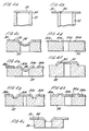
- Figure 4 shows a few of the numerous articles formed of metal and ceramic components which may be produced according to the present invention by the exploitation of technology that allows joining and formation of hermetic seals between metals and ceramics.
- the articles are cylindical in geometry and are shown in part and in section. For simplicity of representation, the layer of deformable metal has not been shown.
- Figure 4a shows a metallic disc 30 joined to a ceramic tube 32 by an ultrasonic seal 34. Like parts in the other figures are designated by like references.
- the metallic component is an annular disc.
- the metallic component of Figure 4c has been provided with a locational dimple 36 which abuts against the ceramic structure 32 to define the relative location of the two parts.
- Figure 4d shows an article with two metallic components 30a, 30b.
- FIG 4e the central metallic component 30b has been provided with a locational dimple as described hereinbefore.
- Figures 4f, 4g, 4h and 4i all show structures in which the relative positions of the metallic and ceramic components 30, 32 are defined by projections on the metallic component 30 which abut against the sides of recesses or projections in the ceramic structure 32.
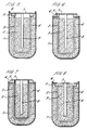
- Figures 5 to 8 of the drawings show diagrammatically four different constructions of sodium/sulphur cell similar to the cell shown in Figure 1, which can be readily manufactured using the method of this invention.
- the layer of deformable metal has not been shown.
- Parts of the cells corresponding to parts of the cell of Figure 1 have the same references.
- the cell of Figure 8 is most similar to that of Figure 1 in that the alpha alumina disc 5 serves for closure of the cup 2, there being only a small hole therein for receiving the current collector 8.
- the terminal disc 7 serves for closure of the cup 2, the alpha alumina member 5 being in the form of a ring secured about the open end of the cup 2 with the discs 6 and 7 secured thereto.
- the connections between the alpha alumina member 5 and the metal members 6 and 7 can be made by the method of this invention.
- FIG. 9 of the drawings shows the construction of part of another sodium/sulphur cell which can be readily manufactured using the method of this invention.
- the currect collector 8 is initially secured to, or formed integrally with, the terminal disc 7, and the disc 7 is then secured to the alpha alumina member 5 by the method of the invention to seal the electrode compartment 3, with the current collector 8 projecting into the compartment 3 as necessary.
- the disc 7 can be provided as part of a larger member 9 by which the cell can be connected to other cells, for example as described in WO 89/00344.
- An assembly of the construction shown in Figure 9 offers manufacturing advantages as compared with cells as shown in Figure 1. These advantages include a reduced number of components which can also be of simpler construction, and the ability to produce the necessary seals at ambient temperature by the method of this invention, after filling of the electrolyte cup 2 with the sodium electrode material.
- the terminal disc 7 and sealing disc 6 are secured to the disc 5 by diffusion bonding, the cup 2 filled with sodium (or sulphur), and the current collector 8 then inserted and welded to the terminal disc 7. If, as is generally the case, the cell is to be connected to other cells, then an intercell connection member must then be welded to the terminal disc 7 or the current collector 8.
- the ceramic member to which a metal member (or members) is bonded is of alpha alumina, it will be appreciated that other ceramic materials can otherwise be used.
- the Inventors have also attempted to ultrasonically weld together glass components and metal composite components (as described previously). It was found that if the glass component was too thin, it was susceptible to failure during loading, but it was still found possible to deposit a certain amount of aluminium onto the glass and also to leave areas of glass bonded to the aluminium layer of the composite. It is therefore envisaged that it would be possible to form seals between a composite member (as described previously) and a glassy or vitreous member if the vitreous member was sufficiently thick and sufficiently well supported to withstand the force applied during welding. It was further observed that the maximum power absorbed by a weld using a glass component was much lower than that absorbed by a weld using alpha alumina.
- This difference is believed to be due to the difference in surface roughness (coefficient of friction) at the weld interface.
- the maximum power taken from a welding generator during ultrasonic welding depends on the welding load applied, the weld area and the coefficient of friction between components to be welded.
- ultrasonic welds could be produced between components as described previously in which the substrate of the composite member was formed of any one of the following materials: aluminium with ceramic reinforcing fibres; plastic materials; plastics with metallic, ceramic or glass reinforcing fibres.
- the essential feature is that the substrate member is formed of a material which is harder than the deformable metal used.
Claims (30)
- Une pile au sodium/soufre comprenant un élément en céramique et un élément composite, ledit élément composite comprenant un élément formant substrat et une couche de métal déformable mécaniquement fixée audit élément formant substrat, ledit élément formant substrat étant formé d'une matière qui est plus dure que ledit métal déformable, dans laquelle ledit élément en céramique et ladite couche de métal déformable sont hermétiquement jointes ensemble par une liaison en phase solide formée par soudage par ultrasons.
- Une pile au sodium/soufre selon la revendication 1, dans laquelle ledit élément formant substrat est formé d'un métal.
- Une pile au sodium/soufre conformément à la revendication 2, dans laquelle ledit élément formant substrat est formé d'acier et ladite couche de métal déformable est choisie dans le groupe constitué d'aluminium et d'alliages d'aluminium.
- Une pile au sodium/soufre selon l'une quelconque des revendications précédentes, dans laquelle ladite couche de métal déformable à une épaisseur dans le domaine allant jusqu'a 450 microns inclus.
- Une pile au sodium/soufre selon la revendication 4, dans laquelle ladite couche de métal déformable a une épaisseur dans le domaine allant jusqu'à 150 microns inclus.
- Une pile au sodium/soufre selon la revendication 5, dans laquelle ladite couche de métal déformable a une épaisseur dans le domaine allant jusq'à 60 microns inclus.
- Une pile au sodium/soufre selon l'une quelconque des revendications 4 à 6, dans laquelle ladite couche de métal déformable a une épaisseur d'au moins 25 microns.
- Une pile au sodium/soufre selon l'une quelconque des revendications précédentes, dans laquelle ledit élément composite a une épaisseur maximale dans le domaine allant jusqu'à 2 mm inclus.
- Une pile au sodium/soufre selon l'une quelconque des revendications précédentes, dans laquelle ledit élément composite est laminaire.
- Une pile au sodium/soufre selon l'une quelconque des revendications précédentes, dans laquelle ledit élément en céramique est formé d'alumine alpha.
- Une pile au sodium/soufre selon l'une quelconque des revendications précédentes, dans laquelle ladite liaison d'assemblage est annulaire.
- Une pile au sodium/soufre selon l'une quelconque des revendications précédentes, comportant en outre une cuvette à électrolyte solide, l'élément an céramique consistant en un disque en céramique fermant l'extrémité ouverte de la cuvette; et un collecteur de courant s'étendant à travers le disque en céramique jusque dans la cuvette, ledit élément composite consistant en un élément terminal en connexion électrique avec le collecteur de courant, ledit élément terminal et ledit disque en céramique étant liés ensemble par ladite liaison d'assemblage en phase solide.
- Une pile au sodium/soufre selon la revendication 12, dans laquelle le disque terminal fait partie d'un élément d'interconnexion pour servir à connecter la pile à d'autres piles.
- Une pile au sodium/soufre selon l'une quelconque des revendications 12 ou 13, dans laquelle le disque terminal est formé en une seule pièce avec le collecteur de courant.
- Une pile au sodium/soufre selon l'une quelconque des revendications précédentes, dans laquelle ledit élément formant substrat est formé d'acier et ladite couche de métal déformable est formée d'une matière résistant à la corrosion.
- Une pile au sodium/soufre selon l'une quelconque des revendications précédentes, dans laquelle ladite couche de métal déformable est formée d'une matière choisie dans le groupe constitué d'aluminium et d'alliages d'aluminium.
- Un procédé de formation d'une pile au sodium/soufre comprenant un élément en céramique et un élément composite, ledit élément en céramique comportant un élément formant substrat et une couche de métal déformable mécaniquement fixée audit élément formant substrat, ledit élément formant substrat étant formé d'une matière qui est plus dure que ledit métal déformable, le procédé comprenant les opérations consistant à positionner ledit élément en céramique et ledit élément composite l'un relativement à l'autre de telle façon que ledit élément en céramique soit adjacent à ladite couche de métal déformable et à fixer ledit élément en céramique ou vitreux et ladite couche de métal déformable ensemble par soudage par ultrasons pour former un joint hermétique.
- Un procédé selon la revendication 17, dans lequel ledit élément formant substrat est formé d'un métal.
- Un procédé selon la revendication 18, dans lequel ledit élément formant substrat est formé d'acier et ladite couche de métal déformable est formée d'une matière choisie dans le groupe constitué d'aluminium et d'alliages d'aluminium.
- Un procédé selon l'une quelconque des revendications 17 à 19, dans lequel la couche de métal déformable a une épaisseur telle que ledit métal, déformable est amené à vibrer à une interface entre ladite couche de métal déformable et ledit élément en céramique pendant le soudage par ultrasons.
- Un procédé selon la revendication 20, dans lequel ladite couche de métal déformable a une épaisseur dans le domaine allant jusqu'à 450 microns inclus.
- Un procédé selon la revendication 21, dans lequel ladite couche de métal déformable a une épaisseur allant jusqu'à 150 microns inclus.
- Un procédé selon la revendication 22, dans lequel ladite couche de métal déformable a une épaisseur allant jusqu'à 60 microns inclus.
- Un procédé selon l'une quelconque des revendications 21 à 23, dans lequel ladite couche de métal déformable a une épaisseur d'au moins 25 microns.
- Un procédé selon l'une quelconque des revendications 17 à 24, dans lequel ledit élément composite a une épaisseur maximale dans le domaine allant jusqu'à 2 mm inclus.
- Un procédé salon l'une quelconque des revendications 17 à 25, dans lequel ledit élément composite est laminaire.
- Un procédé selon l'une quelconque des revendications 17 à 26, dans lequel ledit élément en céramique est formé d'alumine alpha.
- Un procédé selon l'une quelconque des revendications 17 à 27, dans lequel ladite liaison d'assemblage est annulaire.
- Un procédé selon l'une quelconque des revendications 17 à 28, dans lequel ledit élément formant substrat est formé d'acier et ladite couche de métal déformable est formée d'une matière résistant à la corrosion.
- Un procédé selon l'une quelconque des revendications 17 à 29, dans lequel ladite couche du métal déformable est formée d'une matière choisie dans le groupe constitué d'aluminium et d'alliages d'aluminium.
Applications Claiming Priority (3)
| Application Number | Priority Date | Filing Date | Title |
|---|---|---|---|
| GB898915316A GB8915316D0 (en) | 1989-07-04 | 1989-07-04 | Metal/ceramic bonds |
| GB8915316 | 1989-07-04 | ||
| PCT/GB1990/000999 WO1991000255A1 (fr) | 1989-07-04 | 1990-06-28 | Articles composes d'un element ceramique et d'un element metallique colles ensemble |
Publications (2)
| Publication Number | Publication Date |
|---|---|
| EP0480962A1 EP0480962A1 (fr) | 1992-04-22 |
| EP0480962B1 true EP0480962B1 (fr) | 1995-03-22 |
Family
ID=10659512
Family Applications (1)
| Application Number | Title | Priority Date | Filing Date |
|---|---|---|---|
| EP90909772A Expired - Lifetime EP0480962B1 (fr) | 1989-07-04 | 1990-06-28 | Piles soufre/sodium comprenant une partie ceramique solidaire d'une partie metallique |
Country Status (11)
| Country | Link |
|---|---|
| US (1) | US5270135A (fr) |
| EP (1) | EP0480962B1 (fr) |
| JP (1) | JPH05500495A (fr) |
| KR (1) | KR920703479A (fr) |
| AT (1) | ATE120159T1 (fr) |
| CA (1) | CA2062785A1 (fr) |
| DD (1) | DD296585A5 (fr) |
| DE (1) | DE69018077T2 (fr) |
| GB (1) | GB8915316D0 (fr) |
| WO (1) | WO1991000255A1 (fr) |
| ZA (1) | ZA905186B (fr) |
Families Citing this family (11)
| Publication number | Priority date | Publication date | Assignee | Title |
|---|---|---|---|---|
| GB9111982D0 (en) * | 1991-06-04 | 1991-07-24 | Chloride Silent Power Ltd | An alkali metal energy conversion cell |
| US5320915A (en) * | 1992-12-11 | 1994-06-14 | Hughes Aircraft Company | Glass sealing of electrochemical storage cell structures |
| US5378551A (en) * | 1993-07-19 | 1995-01-03 | Motorola, Inc. | Rechargeable battery cell having integral vibrating means |
| US5766789A (en) * | 1995-09-29 | 1998-06-16 | Energetics Systems Corporation | Electrical energy devices |
| DE19833590C1 (de) * | 1998-07-28 | 2000-03-30 | Dietmar Eifler | Verfahren zur Verschweißung eines ausgedehnten optischen Bauteils an eine Metallbefestigung, deren Verwendung sowie die optische Baugruppe |
| DE102008014320A1 (de) * | 2008-03-14 | 2009-09-17 | Fraunhofer-Gesellschaft zur Förderung der angewandten Forschung e.V. | Ultraschallunterstütztes Rührreibschweißen |
| DE102008002959A1 (de) * | 2008-07-22 | 2010-01-28 | Schunk Sonosystems Gmbh | Verfahren zum abdichtenden Verschweißen von Elementen mittels Ultraschall |
| US8603659B2 (en) * | 2008-10-03 | 2013-12-10 | General Electric Company | Sealing glass composition and article |
| WO2012110244A1 (fr) * | 2011-02-18 | 2012-08-23 | Schott Ag | Passage |
| CN103133465B (zh) * | 2013-03-06 | 2015-11-18 | 哈尔滨工业大学深圳研究生院 | 大气环境下硬质材料实现可控间隙连接的方法 |
| US10052713B2 (en) * | 2015-08-20 | 2018-08-21 | Ultex Corporation | Bonding method and bonded structure |
Family Cites Families (10)
| Publication number | Priority date | Publication date | Assignee | Title |
|---|---|---|---|---|
| GB981741A (en) * | 1961-04-21 | 1965-01-27 | Ind Fernand Courtoy Bureau Et | Improvements in and relating to the methods of making assemblies by bonding ceramics, cermets, alloys, heavy alloys and metals of different thermal expansion coefficient |
| NL6414623A (fr) * | 1964-12-16 | 1966-06-17 | ||
| GB1129951A (en) * | 1965-01-29 | 1968-10-09 | Smiths Industries Ltd | Improvements in or relating to the bonding of ceramic members to metal members and of ceramic members to each other |
| GB1586073A (en) * | 1978-05-24 | 1981-03-18 | Chloride Silent Power Ltd | Metal-to-ceramic seal |
| JPS5916282A (ja) * | 1982-07-19 | 1984-01-27 | Yuasa Battery Co Ltd | ナトリウム−硫黄電池の製造法 |
| US4631685A (en) * | 1984-12-07 | 1986-12-23 | General Motors Corporation | Method and apparatus for ultrasonic plastic forming and joining |
| JPS61138473A (ja) * | 1984-12-07 | 1986-06-25 | Yuasa Battery Co Ltd | ナトリウム−硫黄電池とその製造法 |
| GB8609771D0 (en) * | 1986-04-22 | 1986-05-29 | Lilliwyte Sa | Electrochemical cells |
| BE905774A (fr) * | 1986-11-18 | 1987-03-16 | Undatim Ultrasonics | Procede et installation pour la mise en oeuvre d'un dispositif vibrateur electroacoustique. |
| GB8715708D0 (en) * | 1987-07-03 | 1987-08-12 | Chloride Silent Power Ltd | Batteries |
-
1989
- 1989-07-04 GB GB898915316A patent/GB8915316D0/en active Pending
-
1990
- 1990-06-28 US US07/784,391 patent/US5270135A/en not_active Expired - Fee Related
- 1990-06-28 WO PCT/GB1990/000999 patent/WO1991000255A1/fr active IP Right Grant
- 1990-06-28 AT AT90909772T patent/ATE120159T1/de not_active IP Right Cessation
- 1990-06-28 DE DE69018077T patent/DE69018077T2/de not_active Expired - Fee Related
- 1990-06-28 JP JP2509050A patent/JPH05500495A/ja active Pending
- 1990-06-28 KR KR1019920700008A patent/KR920703479A/ko not_active Application Discontinuation
- 1990-06-28 EP EP90909772A patent/EP0480962B1/fr not_active Expired - Lifetime
- 1990-06-28 CA CA002062785A patent/CA2062785A1/fr not_active Abandoned
- 1990-07-03 ZA ZA905186A patent/ZA905186B/xx unknown
- 1990-07-04 DD DD90342486A patent/DD296585A5/de not_active IP Right Cessation
Also Published As
| Publication number | Publication date |
|---|---|
| DE69018077T2 (de) | 1995-07-27 |
| GB8915316D0 (en) | 1989-08-23 |
| DD296585A5 (de) | 1991-12-05 |
| US5270135A (en) | 1993-12-14 |
| ZA905186B (en) | 1991-04-24 |
| JPH05500495A (ja) | 1993-02-04 |
| CA2062785A1 (fr) | 1991-01-05 |
| WO1991000255A1 (fr) | 1991-01-10 |
| ATE120159T1 (de) | 1995-04-15 |
| EP0480962A1 (fr) | 1992-04-22 |
| DE69018077D1 (de) | 1995-04-27 |
| KR920703479A (ko) | 1992-12-18 |
Similar Documents
| Publication | Publication Date | Title |
|---|---|---|
| EP0480962B1 (fr) | Piles soufre/sodium comprenant une partie ceramique solidaire d'une partie metallique | |
| US2946119A (en) | Method and apparatus employing vibratory energy for bonding metals | |
| US8186566B2 (en) | Method for cohesively bonding metal to a non-metallic substrate | |
| Matheny et al. | Ultrasonic welding of metals | |
| EP0484368B1 (fr) | Procede de fermeture d'une extremite du boitier d'une cellule a sodium/soufre et cellule a sodium/soufre produite par ce procede | |
| US5160090A (en) | Method of making high-strength brazed joints | |
| EP0196221B1 (fr) | Procédé de fabrication de matériaux ceramiques composites | |
| JP3209133B2 (ja) | 多数枚積層した金属箔の超音波溶接方法 | |
| US5562716A (en) | Package and method of construction | |
| JP2000195543A (ja) | 絶縁リングと陰極金具の接合方法、結合構造及びこれを用いたナトリウム−硫黄電池 | |
| CN217045001U (zh) | 一种银镍合金-纯铝触头的爆炸复合法制备结构 | |
| JP2000323167A (ja) | ナトリウム−硫黄電池の製造方法及び製造装置 | |
| AU680634B2 (en) | Package and method of construction | |
| JPS6297240A (ja) | X線管用陽極構体及びその製造方法 | |
| JPS6354994B2 (fr) | ||
| JPH0723269B2 (ja) | ナトリウム―硫黄電池における金属製部品とセラミック製部品の結合方法 | |
| JPH10120474A (ja) | アルミニウムとセラミックスとの接合方法 | |
| CN114535772A (zh) | 一种银镍合金-纯铝触头的爆炸复合法制备结构及工艺 | |
| WO2002003483A1 (fr) | Traversee de logement de batterie | |
| JPH0675407B2 (ja) | ナトリウム−イオウ電池の容器接合部の構造 | |
| JP4170636B2 (ja) | ナトリウム−硫黄電池 | |
| JP2001176543A (ja) | ナトリウム−硫黄電池の製作方法 | |
| Matheny | EWI, Columbus, OH, USA Note: This chapter is a revised and updated version of Chapter 9 “Ultrasonic metal welding” by K. Graff, originally published in New Developments in Advanced Welding, ed. N. Ahmed, Woodhead Publishing Limited, 2005, ISBN: 978-1-85573-970-3. | |
| EP0517389A2 (fr) | Elément de conversion d'énergie à métal alcalin | |
| JPH0589909A (ja) | 密閉形二次電池の製造方法 |
Legal Events
| Date | Code | Title | Description |
|---|---|---|---|
| PUAI | Public reference made under article 153(3) epc to a published international application that has entered the european phase |
Free format text: ORIGINAL CODE: 0009012 |
|
| 17P | Request for examination filed |
Effective date: 19920114 |
|
| AK | Designated contracting states |
Kind code of ref document: A1 Designated state(s): AT BE DE DK ES FR GB IT LU NL SE |
|
| 17Q | First examination report despatched |
Effective date: 19930622 |
|
| GRAA | (expected) grant |
Free format text: ORIGINAL CODE: 0009210 |
|
| ITF | It: translation for a ep patent filed |
Owner name: FUMERO BREVETTI S.N.C. |
|
| RAP1 | Party data changed (applicant data changed or rights of an application transferred) |
Owner name: SILENT POWER GMBH FUER ENERGIESPEICHERTECHNIK |
|
| AK | Designated contracting states |
Kind code of ref document: B1 Designated state(s): AT BE DE DK ES FR GB IT LU NL SE |
|
| PG25 | Lapsed in a contracting state [announced via postgrant information from national office to epo] |
Ref country code: NL Free format text: LAPSE BECAUSE OF NON-PAYMENT OF DUE FEES Effective date: 19950322 Ref country code: ES Free format text: THE PATENT HAS BEEN ANNULLED BY A DECISION OF A NATIONAL AUTHORITY Effective date: 19950322 Ref country code: DK Effective date: 19950322 Ref country code: BE Effective date: 19950322 Ref country code: AT Effective date: 19950322 |
|
| REF | Corresponds to: |
Ref document number: 120159 Country of ref document: AT Date of ref document: 19950415 Kind code of ref document: T |
|
| REF | Corresponds to: |
Ref document number: 69018077 Country of ref document: DE Date of ref document: 19950427 |
|
| PG25 | Lapsed in a contracting state [announced via postgrant information from national office to epo] |
Ref country code: SE Effective date: 19950622 |
|
| PGFP | Annual fee paid to national office [announced via postgrant information from national office to epo] |
Ref country code: FR Payment date: 19950627 Year of fee payment: 6 |
|
| PGFP | Annual fee paid to national office [announced via postgrant information from national office to epo] |
Ref country code: DE Payment date: 19950629 Year of fee payment: 6 |
|
| PG25 | Lapsed in a contracting state [announced via postgrant information from national office to epo] |
Ref country code: LU Free format text: LAPSE BECAUSE OF NON-PAYMENT OF DUE FEES Effective date: 19950630 |
|
| ET | Fr: translation filed | ||
| NLV1 | Nl: lapsed or annulled due to failure to fulfill the requirements of art. 29p and 29m of the patents act | ||
| PLBE | No opposition filed within time limit |
Free format text: ORIGINAL CODE: 0009261 |
|
| STAA | Information on the status of an ep patent application or granted ep patent |
Free format text: STATUS: NO OPPOSITION FILED WITHIN TIME LIMIT |
|
| 26N | No opposition filed | ||
| PGFP | Annual fee paid to national office [announced via postgrant information from national office to epo] |
Ref country code: GB Payment date: 19960812 Year of fee payment: 7 |
|
| PG25 | Lapsed in a contracting state [announced via postgrant information from national office to epo] |
Ref country code: FR Effective date: 19970228 |
|
| PG25 | Lapsed in a contracting state [announced via postgrant information from national office to epo] |
Ref country code: DE Effective date: 19970301 |
|
| REG | Reference to a national code |
Ref country code: FR Ref legal event code: ST |
|
| PG25 | Lapsed in a contracting state [announced via postgrant information from national office to epo] |
Ref country code: GB Free format text: LAPSE BECAUSE OF NON-PAYMENT OF DUE FEES Effective date: 19970628 |
|
| GBPC | Gb: european patent ceased through non-payment of renewal fee |
Effective date: 19970628 |
|
| PG25 | Lapsed in a contracting state [announced via postgrant information from national office to epo] |
Ref country code: IT Free format text: LAPSE BECAUSE OF NON-PAYMENT OF DUE FEES Effective date: 20050628 |