EP0477976B1 - Adjusting technique for a digital elevator drive system - Google Patents
Adjusting technique for a digital elevator drive system Download PDFInfo
- Publication number
- EP0477976B1 EP0477976B1 EP91116570A EP91116570A EP0477976B1 EP 0477976 B1 EP0477976 B1 EP 0477976B1 EP 91116570 A EP91116570 A EP 91116570A EP 91116570 A EP91116570 A EP 91116570A EP 0477976 B1 EP0477976 B1 EP 0477976B1
- Authority
- EP
- European Patent Office
- Prior art keywords
- signal
- magnitude
- providing
- sensed
- indicative
- Prior art date
- Legal status (The legal status is an assumption and is not a legal conclusion. Google has not performed a legal analysis and makes no representation as to the accuracy of the status listed.)
- Expired - Lifetime
Links
Images


Classifications
-
- B—PERFORMING OPERATIONS; TRANSPORTING
- B66—HOISTING; LIFTING; HAULING
- B66B—ELEVATORS; ESCALATORS OR MOVING WALKWAYS
- B66B1/00—Control systems of elevators in general
- B66B1/34—Details, e.g. call counting devices, data transmission from car to control system, devices giving information to the control system
- B66B1/3407—Setting or modification of parameters of the control system
-
- B—PERFORMING OPERATIONS; TRANSPORTING
- B66—HOISTING; LIFTING; HAULING
- B66B—ELEVATORS; ESCALATORS OR MOVING WALKWAYS
- B66B1/00—Control systems of elevators in general
- B66B1/34—Details, e.g. call counting devices, data transmission from car to control system, devices giving information to the control system
-
- B—PERFORMING OPERATIONS; TRANSPORTING
- B66—HOISTING; LIFTING; HAULING
- B66B—ELEVATORS; ESCALATORS OR MOVING WALKWAYS
- B66B19/00—Mining-hoist operation
- B66B19/007—Mining-hoist operation method for modernisation of elevators
Definitions
- This invention relates to elevators, and more particularly, electric control systems and devices therefor. Still more precisely, the invention relates to a computer assisted method for initially adjusting, at time of installation, a control parameter for controlling an elevator system.
- a portable personal computer having a data base and algorithm that presents menus to the adjuster for his easy selection of items by which the elevator system may be measured and tuned, using virtual measuring and tuning components operated by means of the programs of the computer.
- the PC is temporarily connected to a microprocessor-controlled elevator system for operating as a virtual instrument so that the task of assembling and carrying a number of discrete measuring devices, e.g., an oscilloscope, a strip-chart recorder, and a spectrum analyzer, can be avoided by the simple substitution of a single "virtual" instrument capable of emulating any or all of these instruments.
- the programs of the computer can be devised, according to that disclosure, to enable a single apparatus to be used for the tuning and measurement of the whole elevator system and to improve the standard of tuning and measurements.
- the invention further suggests remote monitoring and tuning by means of telephone lines without entering the machine room and can be operated by technicians of different skill levels, depending on a hierarchy of skills as set forth. Large elevator groups or elevators similar to each other can be started up faster because tuning parameters can be transferred from one elevator to another. No separate measuring instruments are needed because the system employs a computer which comprises all the necessary virtual components, for example, in the form of icons symbolizing operations that functionally correspond to the operation of a real, physical instrument or component.
- a compensation signal is generated in a function generator which completely compensates the corresponding position error until the end of the travel. Stochastic position errors are equalized in an integrating amplifier until the end of the travel.
- a pattern-recognizing self-tuning controller has come to be known.
- Said known controller is provided for controlling a process wherein measured characteristics including at least one peak for an error signal, derived from the differences occurring over time between the values of a process controlled variable and a desired set-point level for that variable, are used for identifying the behaviour pattern of the error signal so that an operating parameter of the controller can be changed as required to minimize process recovery time whenever the process is subsequently disturbed or an abrupt change is made to the set-point level at some later point.
- the preferred embodiment of said known device is disclosed in the form of a proportional-integral-derivative (PID) controller in which the PID coefficients are calculated in accordance with prescribed relationships that are based on damping, overshoot and time period characteristics of the error signal.
- PID proportional-integral-derivative
- said document does not disclose any computer assisted method for initially adjusting a control parameter for controlling an elevator system at the time of installation.
- the object of the present invention is to provide self-adjusting technique for a digital elevator drive system.
- the method according to the invention is defined as a computer assisted method for initially adjusting, at the time of installation, a control parameter for controlling an elevator system, exhibiting the features set out with claim 1.
- Dependent claims 2 to 10 exhibit further improvements of the subject-matter of claim 1.
- a drive system is made able to adjust itself automatically.
- the elevator drive system is designed to use information the system obtains by means of its internal signals to tune itself.
- the information obtained from the internal signals of the system is used to display sufficient information to enable the adjuster to make appropriate hardware adjustments. This may be accomplished by means of built-in display devices or by means of an interchange of signals between a service tool and the elevator control system connected thereto.
- control parameters can be subdivided into sensitive parameters that have a severe influence on the drive performance which will be adjusted and others that can be set to values that will have a fixed relationship to those sensitive parameters that will be adjusted.
- the adjusting can be performed by special software driven in operational modes internal to the elevator system itself. These may include special excitation of control loops and the processing of feedback signals.
- each software control parameter e.g., a regulated gain or time constant
- a special software routine which may be set up to execute automatically upon initiation at the time of installation.
- some devices within any elevator control may be manually adjustable, and therefore it may often be necessary, for example, to adjust resistors in the controller cabinet.
- the drive system may be configured to provide precise information concerning the adjustment that needs to be made.
- a drive and brake subsystem may be decoupled from other subsystems during initial "exercising" to determine needed adjustments or while actually making such adjustments.
- the other elevator control systems are reconnected. This may be done automatically or by virtue of actual disconnections and reconnections. In this way, the setup of the complete control system may be decoupled from the tuning of other subsystems, such as the drive.
- the polarity of the feedback signals e.g., armature current, velocity, motor field current, are checked by means of checking the connections and observing the run direction.
- a brake resistor adjustment can be made to obtain a smooth brake lift in order to reduce start jerk of the elevator.
- the motor field current may be adjusted automatically.
- the feed forward gain of the drive system may be automatically adjusted.
- a start time delay for delaying initiation of a start torque profile which bypasses the velocity loop during starting may be adjusted automatically.
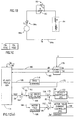
- Fig. 1A illustrates a signal processor 10 which is illustrated as a microprocessor but which may be any discrete or integrated circuit which carries out the functions to be described hereinafter.
- the signal processor comprises a central processing unit (CPU) 12 which communicates with a data, address and control (D,A,C) bus 14, also in communication with a random access memory (RAM) 16, and electrically erasable, programmable, read-only memory (EPROM) 18, and an input/output (I/O) device 20.
- CPU central processing unit
- D,A,C data, address and control
- RAM random access memory
- EPROM electrically erasable, programmable, read-only memory
- I/O input/output
- the signal processor 10 of Fig. 1A is shown interfacing with an elevator system 22 including a car 24 having a rope 26 laid over a sheave 28 attached to a counterweight 30 in a hoistway in a building.
- the sheave 28 is driven by a motor which in the case illustrated in Fig. 1A, is a Ward-Leonard control system having a DC motor, having its output shaft 34 attached to the sheave 28 and having its armature energized by an armature current (I A ) on a line 36 provided by a DC generator 38 which is in turn driven by a shaft 40 of an AC motor 42.
- Three-phase utility power on lines 44, 46, 48 is provided to the AC motor 42 for driving it at constant speed corresponding to the frequency of the utility.
- a field winding 50 of the DC motor 32 is energized by a motor field current (I MF ) on a line 52 provided by an SCR circuit 54 controlled by a motor field dictation current on a line 56 from the signal processor's I/O device 20.
- I MF motor field current
- a sensed motor field current signal is provided to the signal processor 10 on a line 58 and may be obtained by means of a small resistance 60 inserted in series with the signal line 52. A small voltage drop is provided across the resistor from which the motor field current may be inferred.
- the armature current on line 36 may be sensed by inserting a resistor 62 in the armature line 36 in order to provide a sensed armature current signal on a line 64 to the I/O device 20.
- a pair of lines 64a, 64b, which together constitute the signal line 64 may be utilized to indicate the magnitude of the armature voltage (VA).
- a DC generator field winding 66 is energized by a signal on a line 68 from an SCR circuit 70 controlled by a torque command signal (ALPHA GF) on a line 72 from the I/O device 20.
- a resistor 74 in the signal line 68 provides a voltage drop on a signal line 76 indicative of the magnitude of the generator field current for the I/O device 20.
- a tachometer 80 attached by means of a linkage or shaft 81 to the sheave or motor shaft 34 provides a sensed velocity signal on a line 82 to the I/O device 20.
- the tachometer 80 may be a position sensor and the signal on line 82 may be a position signal from which may be inferred velocity based on an internal clock 83 within the signal processor 10.
- a brake 84 as shown in Fig. 1B, represented by a resistance and an inductance, may be energized by a brake current (I B ) on a line 84a from a voltage source 84b provided upon closure of a switch 84c.
- An adjustable resistor 85 permits the exponential size of the brake current to be adjusted in slope according to a desired smoothness for brake release as shown subsequently in connection with Figs. 4 and 11.
- Another switch 86 may be provided which will be open during the initial brake opening process in order to provide the desired degree of moving but which will be closed to short out resistor 85 after detecting car motion.
- the smooth operation of the brake can also be achieved by other techniques, such as an open loop control of the brake voltage (ramp up of brake voltage) or a closed loop control of the brake current.
- the open loop technique of Fig. 1B is presently preferred and is shown in dotted lines in Figs. 1A and 1C.
- the brake 84 may be energized as shown in Figs. 1A and 1C in a closed loop control by a DC brake current (I B ) on a line 90 which, when energized, causes a restraining device 92 to be lifted, for example, from the sheave 28 in order to permit it to rotate.
- the brake current on the line 90 is sensed by means of a resistor 94 which provides a sensed brake current signal on a line 96 to the I/O device 20.
- a lift brake (L B ) signal on a line 98 is provided to an SCR circuit 100 which provides the brake current on the line 90 in response to a stepped-down AC voltage on a line 102 provided by a transformer 104, which is in turn energized by a line 106 which may be a single phase AC voltage obtained, for example, from two of the three phase utility power lines 44, 46.
- a number of hoistway devices such as position sensors, call buttons, indicators, and car buttons and indicators (not shown and provided by means of a traveling cable ⁇ not shown ⁇ ) are provided by means of signal lines symbolized by a signal line 110.
- a service tool 112 which may be a "dumb” terminal or a “smart” terminal, as the case may be, is used by a service technician to carry out the methods claimed herein. It or the elevator system itself may embody some of the routines for carrying out these methods in software.
- a dashed line 116 is there shown to separate the hardware functions of the figure from a preferred software embodiment of the invention residing in the elevator controller itself.
- the hardware shown on the right side of dashed line 116 in Fig. 1B is the same as that shown in Fig. 1A.
- the software functions shown on the left of the dashed line 116 in Fig. 1B are functional blocks which are carried out in software routines which may be stored in an EPROM 18, such as is shown in the signal processor 10 of Fig. 1A.
- These routines may be executed in any number of different approaches which will be apparent to those skilled in the art of programming based on the description of the functional blocks to be described herein. It should be understood that although many very detailed functional blocks are to be described, many of these functions are somewhat peripheral to the invention disclosed herein and are disclosed for purposes of completeness and form the context of the invention, rather than a limitation thereof.
- the DC generator 38 has its field 66 excited in order to generate an armature current on line 36 of sufficient magnitude to accelerate the DC motor 32 in conformance with a speed profile provided by a velocity generator 124 which provides a velocity profile signal (V REF ) on a line 126.
- the velocity profile generator was, in former days, carried out in discrete components located in one or more controllers. Such components included relatively large size resistors and relay switches for shorting out portions of the resistors in steps so as to weaken or strengthen the generator field, depending on the degree of acceleration desired.
- a velocity control loop comprises a filtered velocity command signal on a line 128 which is compared to a sensed velocity signal on the line 82.
- the difference therebetween is provided as a difference signal on a line 130 to a velocity controller 132, which may be of the proportional-integral type, and which provides an output signal on a line 134 to a summing junction 136 responsive to a summed signal on a line 138 from a summing junction 140.
- the summing junction 136 provides a summed signal on a line 142 to a summing junction 144 responsive to the sensed armature current on line 64.
- a difference signal on a line 146 is provided to an adaptive armature current controller 148.
- the adaptive controller 148 provides a control signal on a line 158 to the SCR circuit 70 for controlling the magnitude of the generator field current on line 68. Since the magnitude of the current on line 68 controls the magnitude of the armature current on line 36, it thereby controls the speed of the DC motor 32 which is sensed by the tachometer 80 and manifested by the velocity feedback on line 82, which together constitute a closed loop velocity control system.
- the velocity reference profile on line 126 is held in abeyance during the starting process and, although the velocity loop is still operative, it is merely provided with a small magnitude creep velocity signal on a line 162, which is added to the zero magnitude reference profile signal on line 126 in a summer 164 which provides a summed signal on a line 166 to a filter 168, which in turn provides a filtered signal on line 128 to a summing junction 170, which was previously described for summing the signals on lines 82 and 128.
- the output of the velocity controller 132 which attempts to zero the input signal on line 130, is summed to a signal on 138 which represents the summation of a feed forward gain signal on a line 172 and a start control torque signal on a line 174.
- a feed forward gain functional block 176 and a start logic functional block 178.
- start logic block 178 The function of the start logic block 178 will not be described in great detail here, except to say that it is responsive to a lift brake signal on a line 180 from the velocity profile generator 124 and, in response thereto, initiates the start control torque signal on line 174, which provides an increasing torque command signal on the line 174 until velocity is sensed on line 82, at which point the increase is stopped and the magnitude of the start command torque signal on line 174 is thereafter held constant.
- the velocity signal on line 82 once motion is indicated, initiates a start profile signal on a line 182 which causes the velocity profile generator 124 to begin providing the speed profile on the line 126.
- the lift brake signal on the line 96 which may be the same as the lift brake signal on line 180, is provided to the SCR device 100 or alternatively the switch 84c in order to begin the brake lift process.
- the timing and slope of the start control torque signal on line 174 may be set up to cause the open loop start torque profile to level off and the velocity loop to begin tracking a velocity profile command signal at the point when the brake 92 has just lifted from the sheave 28.
- the feed forward functional block 176 is provided in order to dictate the magnitude of the signal on line 172 in such a way as to better control the acceleration and deceleration of the motor 32 during the whole running process. This may be done in the manner shown in abstract form in Fig. 1B by adding the magnitude of the signal on line 172 to a summing junction 140. In any event, the feed forward gain functional block 176 is controlled by an acceleration reference signal provided on a line 186 from the velocity profile generator 124.
- a motor field dictation functional block is required as shown in a block 188 and is responsive to the summed signal on line 166 for providing a motor field dictation current for a brief period of time typically near the end of the acceleration on start-up to running speed (e.g., after 80% of the desired speed has been achieved) and at the beginning of the slowdown deceleration until the speed declines to 80% of running speed, at which point the armature current control circuit utilizing the velocity control loop takes over the deceleration task.
- a control signal is provided on a line 190 and commands a motor field current level, which is compared in a summing junction 192 with the sensed motor field current on line 58.
- the difference therebetween is indicated by a difference signal on a line 194, which is provided to a PI controller 196 for controlling by means of a control signal on a line 198, the SCR circuit 54 previously described in connection with Fig. 1A.
- This invention disclosure describes a technique that makes the drive system itself able to adjust all critical parameters.
- the initial setup of the drive system is subdivided into the following tasks:
- the polarities of factors that affect the run direction have to be in an appropriate combination.
- the direction of the car movement depends on the direction in which the ropes are laid over the drive sheave.
- the factors determining the sense of rotation of the motor are:
- the feedback values have to have the appropriate polarity.
- these values are:
- the drive system sets the elevator in movement using constant firing angle for the generator field and the motor field.
- all feedback signals have to be of the same polarity as the firing angles.
- the actual polarity of the armature current feedback depends on the torque condition of the motor.
- the driving motor has to pull the elevator out of the brake.
- the routine measures and registers the signs of the feedback signals. At that point, the elevator is stopped, and it is determined whether any sign faults exist, and if so, to correct any such wrong polarities in the feedback signals or actuator polarity by using a software table stored in EPROM 18, which is shown in Fig. 3.
- the software procedure will internally change the polarity of the corresponding input (sensed armature current on line 64) or the output firing angle signal (ALPHA GF) on line 72.
- a sign fault of the velocity feedback signal such may also be corrected in software, or the tool 112 may be prompted to display the appropriate information (encoder connections to be changed) and be started again as soon as the serviceman indicates that the leads have been checked or swapped.
- the system can be operated in a closed loop mode; thus, the elevator can be moved to conduct further setups.
- a step 202 is next executed by the signal processor 10 of Fig. 1A in accordance with a series of steps which may be the same or similar to those shown in this figure.
- the steps are stored in a program in the EPROM 18.
- the DC generator field control signal on line 72 and the DC motor field control signal on line 56 are provided by the signal processor 10 in an open loop fashion in order to cause the DC motor 32 to move slightly so that the sense and direction of movement may be determined.
- a step 204 after a few seconds, the sign of the sensed armature current on line 64 is registered in the RAM 16 of the signal processor 10. Also, the sign of the sensed velocity signal on line 84 is registered as well.
- the open loop command signals on lines 72 and 56 are stopped and the elevator stops, as indicated in a step 206.
- the observed run direction is obtained before changing signs.
- the consistency or lack of consistency in the signs of the feedback signals are determined as indicated in a step 208. This is done by consulting the table shown in Fig. 3.
- changes in the sign of the signals as received can be made in software by changing the interpretation of the received sign to its negation or by changing the sign of the generator field firing angle (ALPHA GF).
- a step 212 can be executed in which the interpretation of the signs of those feedback signals or the firing angle is changed in software according to Fig. 3.
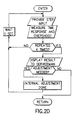
- a step 214 is executed in which a determination is made as to whether or not the sign of the sensed velocity signal is inconsistent with the observed run direction of the elevator car. If so, the interpretation of the sign can be negated in software, for example, as shown previously in connection with the armature current feedback, or, as shown in Fig. 2A, a prompt can be issued to the serviceman by means of the service tool 112 to swap the leads on the tachometer 80, as shown in step 216.
- the serviceman swaps the leads, he can make an entry on the service tool which will provide a signal on the line 113 to the signal processor 10 and a determination made in a step 218 that the leads have indeed been swapped, and the whole process can be repeated to ensure that sign consistency has now been achieved. If there is no inconsistency detected in a step 214, then a return can be directly made in a step 220.
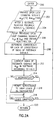
- the adjustment of the brake resistor has to be made to obtain a smooth brake lifting in order to reduce the start jerk of the elevator.
- a series of steps is commenced by first entering in a step 224 and executing a step 226 in which a lift brake command is provided on the line 98 to the switch 84c of Figs. 1A, 1B, and 1C.
- a timer is started as indicated in a step 228 and a wait state is entered until motion is detected as indicated in a step 230, at which point the timer is stopped as indicated in a step 232 and the brake opening time is obtained as indicated in a step 234.
- a step 240 determines when the serviceman indicates by a return signal via the service tool that the adjustment has been made and the steps 226, 236 are again executed as before.
- step 242 determines whether or not it is less than the level 238. If not, then it is equal and a return is made in a step 244. If it is less, then a determination is made in a step 246 as to whether or not brake opening time is greater than a second selected level 248, as shown in Fig. 4. If so, a return is made in step 244.
- a prompt is provided as indicated in a step 250 to the serviceman to increase the brake resistance in a small step and after receiving an indication from the serviceman that the adjustment has been made, as determined in a step 240, then the entire program is run again, as before, until the brake resistance causes the first selected opening time level to either be equal to the first selected level 238 or to be less than that level and greater than the level 248.
- the motor field current is a parameter which determines the field operating point of the motor. There are two different values of the required motor field current:
- the setting of the motor field current may be done at low speed.
- the motor will be running at 25% of the rated speed and the starting or initial value of the motor field current will be a suitable value with respect to the applicable range of the motor, e.g., two Amps.
- the drive system After entering at a step 260 in Fig. 2C, the drive system checks in a step 262 if the dictated speed is reached. In this case, the first phase of the adjustment can begin. After making sure the system is up to 25% of rated speed in steps 264, 266, the system measures the armature voltage and checks if it corresponds to the desired value (25% of the rated armature voltage) as shown in a step 268. According to the relationship (25% Varm-rated/Varm-measured), the new dictated field current will be calculated and delivered as shown in step 270.
- the measured armature voltage sampled in a step 276 is compared to the nominal value. The result of the relation (Varm-rated/Varm-measured) will be used to correct the motor field current calculated before and to deliver the final rated field current as shown in a step 278.
- a special routine may be activated in parallel to the motor field current adjustment to measure the peak values of the firing angles during a constant run at the rated speed. The relationship between the measured values and the maximal values of the firing angles provides an information which helps to set the corresponding transformer tap as shown in steps 280-286.
- the armature current controller 148 may be an adaptive PI-controller. To simplify the adjustment, the responses (Iarm-time-min, Iarm-time-max) are set to default values.
- the gain (Iarm-gain-min, Iarm-gain-max) has to be adjusted according to the operating point, i.e., where the system is working, as limited by the discontinuous (Igf) current flow.
- the parameter Iarm-gain-max will be adjusted in the discontinuous operation region, while in the continuous operation region, the parameter Iarm-gain-min will be set.
- the performance criterion used to adjust the armature control loop is the step response. In fact, several steps are provided as shown in Fig. 5.
- the step response is the measured reaction of a control system to a step change in the input.
- DCF discontinuous current flow
- the procedure activates and evaluates the step response four times before the result is displayed. There is a waiting time of one second between two steps to allow a closed loop driving of the speed control and to check the prescribed adjustment area again. After a last step response, the system waits 0.2 seconds and checks the result before setting it as available and displaying at the service tool.
- Fig. 7 shows the variation of the time response, which is mainly evaluated, depending on the parameter.
- the system ramps down and stands still. See Fig. 2D for a flow chart showing the above described procedure.
- the adjustment routine shown in Fig. 2E starts simultaneously with the profile and measures the maximum and the minimum of the speed controller output. The difference between both values will be displayed as an adjustment result. The procedure compares the actual and the old evaluated result to determine the lowest value for the result. Best adjustment is obtained when the lowest result is reached.
- Fig. 8 shows the characteristic of the prescribed speed controller output measurement results at different gain differences
- Fig. 10 shows the variation in time of speed regulator output for three different gains.
- Fig. 10(a) shows feed forward gain too low
- 10(b) shows it too high
- 10(c) shows it optimized.
- the adjustment will be started with a high gain of, e.g., "500”. This will be decremented in steps of "20" as shown in the direction of an arrow 300 in Fig. 8 as long as the evaluation of measurement results delivers decreasing ⁇ values. The adjustment will be continued until the parameter is well tuned and the result is "OK”. In this case, the system ramps down and stops.
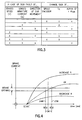
- the adjustment of the start time allows reduction of the jerk at the start of each run.
- this time is the time between the initiation of smooth brake lifting and the beginning of the start-jerk-reduction-routine which increases the armature current in the desired run direction at a creep speed of 5 mm/s.
- Figs. 11(a), (b) and (c) show the variation in time on a common time line of the measured drive signals (brake current, speed, armature current). The current will be increased until the car moves in the desired run direction which will cause the end of the jerk reduction.
- the adjustment will be started using the prescribed parameter "1500 ms". In case of a no load down run condition, this initial parameter will cause a sagging of the car in the up direction due largely to a delayed starting of the armature current profile. Starting will be decremented in different steps, according to the result of the measurement until no sagging of the car, i.e., no rollback, occurs. A pause of two seconds is set between each adjustment starting with new parameter to allow a complete brake closing. The adjustment will be finished if the measured result, i.e., the rollback, is zero.
- Fig. 12 shows the adjustment result depending on the parameter.
- a flow chart is there shown for carrying out the above-described steps. These logical steps will be of course stored in the EPROM 18 of the signal processor 10 of Fig. 1A and will be executed by the signal processor in conjunction with the serviceman using his service tool to cause the program to commence.
- an entrance to the program is made at a step 350, and the initial value of the time delay (t sd ) of Fig. 11(b) is set at an initial value of 1500 milliseconds. This is the time delay from the time (t 0 ) at which the lift brake current commences until the starting torque profile is started at time t 1 .
- a car starts to move at time t 2 , at which time the speed profile is commanded to commence.
- the actual measured speed is shown in Fig. 11(c) by a plot 354 while the dashed line 356 represents the speed profile.
- Fig. 2F the commencement of brake lift is shown in a step 358 after which a step 360 is executed in which the starting torque profile 362 of Fig. 11(b) is started at time t 1 after the time delay t sd .
- a step 360 is executed in which the starting torque profile 362 of Fig. 11(b) is started at time t 1 after the time delay t sd .
- the amount of rollback is measured and stored. If not zero, as detected in a step 366, the time delay is reduced by a selected amount as shown in a step 368 and steps 358, 360, 364, 366 are repeated until rollback is zero, at which point a return is made in a step 370.
Landscapes
- Engineering & Computer Science (AREA)
- Automation & Control Theory (AREA)
- Computer Networks & Wireless Communication (AREA)
- Elevator Control (AREA)
Applications Claiming Priority (2)
| Application Number | Priority Date | Filing Date | Title |
|---|---|---|---|
| US589862 | 1990-09-28 | ||
| US07/589,862 US5157228A (en) | 1990-09-28 | 1990-09-28 | Adjusting technique for a digital elevator drive system |
Publications (3)
| Publication Number | Publication Date |
|---|---|
| EP0477976A2 EP0477976A2 (en) | 1992-04-01 |
| EP0477976A3 EP0477976A3 (en) | 1993-05-05 |
| EP0477976B1 true EP0477976B1 (en) | 1997-12-03 |
Family
ID=24359872
Family Applications (1)
| Application Number | Title | Priority Date | Filing Date |
|---|---|---|---|
| EP91116570A Expired - Lifetime EP0477976B1 (en) | 1990-09-28 | 1991-09-27 | Adjusting technique for a digital elevator drive system |
Country Status (4)
| Country | Link |
|---|---|
| US (1) | US5157228A (fi) |
| EP (1) | EP0477976B1 (fi) |
| DE (2) | DE69128330T2 (fi) |
| FI (1) | FI914531A (fi) |
Families Citing this family (27)
| Publication number | Priority date | Publication date | Assignee | Title |
|---|---|---|---|---|
| JPH06321441A (ja) * | 1993-03-04 | 1994-11-22 | Otis Elevator Co | エレベータ巻上げ装置のプレトルク電流供給方法 |
| US5337878A (en) * | 1993-12-28 | 1994-08-16 | Otis Elevator Company | Assembly and method for adjusting brake force for passenger conveyor emergency brake |
| US5587565A (en) * | 1994-04-14 | 1996-12-24 | Otis Elevator Company | Method for controlling elevator doors |
| US5587566A (en) * | 1994-04-29 | 1996-12-24 | Otis Elevator Company | Method for adjusting an elevator door |
| US5862886A (en) * | 1995-11-29 | 1999-01-26 | Otis Elevator Company | Pretorque to unload elevator car/floor locks before retraction |
| US5777280A (en) * | 1996-08-27 | 1998-07-07 | Otis Elevator Company | Calibration routine with adaptive load compensation |
| JP3899668B2 (ja) * | 1998-04-28 | 2007-03-28 | 株式会社デンソー | 界磁巻線式同期機の駆動制御装置 |
| US6161656A (en) * | 1999-02-01 | 2000-12-19 | Otis Elevator Company | Speed and direction indicator for elevator systems |
| DK174766B1 (da) | 2001-04-30 | 2003-10-27 | Guldmann V As | Fremgangsmåde til drift af et hejseapparat samt et hejseapparat. |
| US6763916B2 (en) * | 2002-04-12 | 2004-07-20 | Delaware Capital Formation, Inc. | Method and apparatus for synchronizing a vehicle lift |
| US7150073B2 (en) * | 2004-04-27 | 2006-12-19 | Delaware Capital Formation, Inc. | Hinge pin |
| US7353916B2 (en) | 2004-06-02 | 2008-04-08 | Inventio Ag | Elevator supervision |
| DK2189410T3 (en) * | 2004-06-02 | 2014-03-10 | Inventio Ag | Elevator Monitoring |
| FI119764B (fi) * | 2007-11-14 | 2009-03-13 | Kone Corp | Kuljetusjärjestelmän parametrien sovittaminen |
| EP2303747B1 (en) * | 2008-06-17 | 2013-04-10 | Otis Elevator Company | Safe control of a brake using low power control devices |
| FI120938B (fi) * | 2009-02-06 | 2010-05-14 | Kone Corp | Järjestely ja menetelmä hissin jarrun ohjaamiseksi |
| FI122183B (fi) * | 2010-03-15 | 2011-09-30 | Kone Corp | Menetelmä ja laite hissin sähkökäytön käyntiinajamiseksi |
| JP2012013546A (ja) * | 2010-06-30 | 2012-01-19 | Toshiba Corp | 移動式炉内計装系駆動装置およびそれを用いた案内管内部の摩擦抵抗監視方法 |
| DE102011101860A1 (de) | 2011-05-12 | 2012-11-15 | Thyssenkrupp Aufzugswerke Gmbh | Verfahren und Vorrichtung zum Steuern einer Aufzugsanlage |
| FI123017B (fi) | 2011-08-31 | 2012-10-15 | Kone Corp | Hissijärjestelmä |
| KR20130057902A (ko) * | 2011-11-24 | 2013-06-03 | 엘에스산전 주식회사 | 엘리베이터의 제어 방법, 엘리베이터 제어 장치 및 이를 이용한 엘리베이터 장치 |
| CN105026297B (zh) * | 2013-02-22 | 2018-01-19 | 通力股份公司 | 用于监视配重式电梯的安全性的方法和装置 |
| US10513414B2 (en) * | 2014-12-29 | 2019-12-24 | Otis Elevator Company | System and method of maintaining performance of a system |
| US10227222B2 (en) | 2015-07-31 | 2019-03-12 | Vehicle Service Group, Llc | Precast concrete pit |
| US10246313B2 (en) | 2015-07-31 | 2019-04-02 | Vehicle Service Group, Llc | Precast concrete pit |
| ES2659789T3 (es) * | 2015-10-08 | 2018-03-19 | Kone Corporation | Método para controlar un ascensor |
| CN115028033A (zh) * | 2021-09-30 | 2022-09-09 | 日立电梯(中国)有限公司 | 电梯变频器速度环pi参数自学习方法、变频器及介质 |
Citations (1)
| Publication number | Priority date | Publication date | Assignee | Title |
|---|---|---|---|---|
| EP0318660A1 (de) * | 1987-11-27 | 1989-06-07 | Inventio Ag | Verfahren und Einrichtung zur Wegregelung eines Positionier-antriebes, insbesondere für Aufzugsanlagen |
Family Cites Families (22)
| Publication number | Priority date | Publication date | Assignee | Title |
|---|---|---|---|---|
| US3584706A (en) * | 1968-10-10 | 1971-06-15 | Reliance Electric Co | Safties for elevator hoist motor control having high gain negative feedback loop |
| US3876918A (en) * | 1972-08-14 | 1975-04-08 | Hitachi Ltd | Electric motor controlling system |
| US3811079A (en) * | 1973-04-25 | 1974-05-14 | Hitachi Ltd | Dc motor control system |
| US3938624A (en) * | 1974-05-10 | 1976-02-17 | Armor Elevator Company, Inc. | Transportation system with motor field control |
| US3973648A (en) * | 1974-09-30 | 1976-08-10 | Westinghouse Electric Corporation | Monitoring system for elevator installation |
| JPS5220210A (en) * | 1975-08-08 | 1977-02-16 | Hitachi Ltd | Control means for d-c motor |
| GB2022882B (en) * | 1978-06-07 | 1982-11-17 | Gec Elliott Automation Ltd | Motor control systems |
| JPS6054227B2 (ja) * | 1979-05-11 | 1985-11-29 | 株式会社日立製作所 | 交流エレベ−タ−の制御装置 |
| DE3005103A1 (de) * | 1980-02-12 | 1981-08-20 | Konstantin Dipl.-Ing. 8910 Landsberg Meyl | Regelkreisoptimierung durch vergleichen |
| SU952396A1 (ru) * | 1981-03-23 | 1982-08-23 | Донецкий Ордена Трудового Красного Знамени Политехнический Институт | Устройство диагностики работы непрерывного стана в темпе прокатки |
| JPS5842573A (ja) * | 1981-09-04 | 1983-03-12 | 株式会社日立製作所 | エレベ−タ−の制御装置 |
| US4602326A (en) * | 1983-12-12 | 1986-07-22 | The Foxboro Company | Pattern-recognizing self-tuning controller |
| US4512442A (en) * | 1984-03-30 | 1985-04-23 | Westinghouse Electric Corp. | Method and apparatus for improving the servicing of an elevator system |
| JPS61249103A (ja) * | 1985-04-26 | 1986-11-06 | Sekisui Chem Co Ltd | Pid制御装置における調節装置 |
| US4658935A (en) * | 1985-08-05 | 1987-04-21 | Dover Corporation | Digital selector system for elevators |
| FI72946C (fi) * | 1985-09-24 | 1987-08-10 | Kone Oy | Automatisk inlaerning av hiss. |
| JPS6356187A (ja) * | 1986-08-22 | 1988-03-10 | Nippon Oochisu Elevator Kk | 誘導電動機の速度制御装置 |
| GB2219408B (en) * | 1987-12-31 | 1991-08-14 | Richard Leigh Aubrey | Electrical voltage tester |
| JPH0764493B2 (ja) * | 1988-06-27 | 1995-07-12 | 三菱電機株式会社 | エレベータの制御装置 |
| US4975627A (en) * | 1988-08-15 | 1990-12-04 | Otis Elevator Company | Brake sequenced elevator motor speed control |
| FI89580C (fi) * | 1988-10-25 | 1993-10-25 | Kone Oy | Foerfarande och anordning foer maetning och avstaemning av ett hissystem |
| US5076399A (en) * | 1990-09-28 | 1991-12-31 | Otis Elevator Company | Elevator start control technique for reduced start jerk and acceleration overshoot |
-
1990
- 1990-09-28 US US07/589,862 patent/US5157228A/en not_active Expired - Lifetime
-
1991
- 1991-09-26 FI FI914531A patent/FI914531A/fi unknown
- 1991-09-27 EP EP91116570A patent/EP0477976B1/en not_active Expired - Lifetime
- 1991-09-27 DE DE69128330T patent/DE69128330T2/de not_active Expired - Fee Related
- 1991-09-27 DE DE199191116570T patent/DE477976T1/de active Pending
Patent Citations (1)
| Publication number | Priority date | Publication date | Assignee | Title |
|---|---|---|---|---|
| EP0318660A1 (de) * | 1987-11-27 | 1989-06-07 | Inventio Ag | Verfahren und Einrichtung zur Wegregelung eines Positionier-antriebes, insbesondere für Aufzugsanlagen |
Non-Patent Citations (1)
| Title |
|---|
| PATENT ABSTRACTS OF JAPAN vol. 11, no. 100 (P-561)(2547) 28 March 1987 & JP-A-61 249 103 (SEKISUI) 06.11.1986 * |
Also Published As
| Publication number | Publication date |
|---|---|
| DE477976T1 (de) | 1992-12-17 |
| FI914531A0 (fi) | 1991-09-26 |
| DE69128330D1 (de) | 1998-01-15 |
| EP0477976A2 (en) | 1992-04-01 |
| DE69128330T2 (de) | 1998-03-26 |
| US5157228A (en) | 1992-10-20 |
| FI914531A (fi) | 1992-03-29 |
| EP0477976A3 (en) | 1993-05-05 |
Similar Documents
| Publication | Publication Date | Title |
|---|---|---|
| EP0477976B1 (en) | Adjusting technique for a digital elevator drive system | |
| EP0948124B1 (en) | Motor controller | |
| EP0338777B1 (en) | Speed control system for elevators | |
| US6720751B2 (en) | Material handling system and method of operating the same | |
| JPH05207799A (ja) | ステッピングモータの制御システム | |
| JPS6161122B2 (fi) | ||
| US5587566A (en) | Method for adjusting an elevator door | |
| JP3017788B2 (ja) | 速度センサを持たないエレベータ装置用の制御装置 | |
| FI72016C (fi) | Foerfarande och anordning foer stabilisering av en likstroemsmotor i en hiss. | |
| US4887695A (en) | Position control method and apparatus for an elevator drive | |
| JP2950149B2 (ja) | オートチューニングコントローラ | |
| EP0914288B1 (en) | Procedure for determining the parameters for an electric drive controlling a synchronous elevator motor with permanent magnets | |
| KR920004286B1 (ko) | 엘리베이터 제어장치 | |
| JP3121067B2 (ja) | エレベータシステムの制御信号の自動チェック及び調整方法 | |
| US11809148B2 (en) | Parameter adjustment method for adjusting control parameters for device that performs servo control | |
| JP2663684B2 (ja) | 電動機速度制御系の調整方法 | |
| WO2022113388A1 (ja) | サーボパラメータの調整方法、及び調整装置 | |
| JPH07107766A (ja) | サーボゲインパラメータチューニング装置 | |
| US5050709A (en) | Elevator control apparatus | |
| CN110422716A (zh) | 一种电梯无称重启动时间的自动检测方法 | |
| CN114057048B (zh) | 决定电梯速度控制系数的方法 | |
| JP2001019290A (ja) | エレベータの制御装置 | |
| JPH0632547A (ja) | エレベータの速度応答制御定数オートチューニング装置 | |
| JP2628884B2 (ja) | インバータの調整方法 | |
| JPH01252479A (ja) | エレベータの調整保守装置 |
Legal Events
| Date | Code | Title | Description |
|---|---|---|---|
| PUAI | Public reference made under article 153(3) epc to a published international application that has entered the european phase |
Free format text: ORIGINAL CODE: 0009012 |
|
| AK | Designated contracting states |
Kind code of ref document: A2 Designated state(s): DE FR GB |
|
| EL | Fr: translation of claims filed | ||
| DET | De: translation of patent claims | ||
| PUAL | Search report despatched |
Free format text: ORIGINAL CODE: 0009013 |
|
| AK | Designated contracting states |
Kind code of ref document: A3 Designated state(s): DE FR GB |
|
| 17P | Request for examination filed |
Effective date: 19931104 |
|
| 17Q | First examination report despatched |
Effective date: 19941219 |
|
| GRAG | Despatch of communication of intention to grant |
Free format text: ORIGINAL CODE: EPIDOS AGRA |
|
| GRAH | Despatch of communication of intention to grant a patent |
Free format text: ORIGINAL CODE: EPIDOS IGRA |
|
| GRAH | Despatch of communication of intention to grant a patent |
Free format text: ORIGINAL CODE: EPIDOS IGRA |
|
| GRAA | (expected) grant |
Free format text: ORIGINAL CODE: 0009210 |
|
| AK | Designated contracting states |
Kind code of ref document: B1 Designated state(s): DE FR GB |
|
| REF | Corresponds to: |
Ref document number: 69128330 Country of ref document: DE Date of ref document: 19980115 |
|
| ET | Fr: translation filed | ||
| PLBE | No opposition filed within time limit |
Free format text: ORIGINAL CODE: 0009261 |
|
| STAA | Information on the status of an ep patent application or granted ep patent |
Free format text: STATUS: NO OPPOSITION FILED WITHIN TIME LIMIT |
|
| 26N | No opposition filed | ||
| PGFP | Annual fee paid to national office [announced via postgrant information from national office to epo] |
Ref country code: GB Payment date: 20000811 Year of fee payment: 10 |
|
| PGFP | Annual fee paid to national office [announced via postgrant information from national office to epo] |
Ref country code: FR Payment date: 20010817 Year of fee payment: 11 |
|
| PGFP | Annual fee paid to national office [announced via postgrant information from national office to epo] |
Ref country code: DE Payment date: 20010820 Year of fee payment: 11 |
|
| PG25 | Lapsed in a contracting state [announced via postgrant information from national office to epo] |
Ref country code: GB Free format text: LAPSE BECAUSE OF NON-PAYMENT OF DUE FEES Effective date: 20010927 |
|
| REG | Reference to a national code |
Ref country code: GB Ref legal event code: IF02 |
|
| GBPC | Gb: european patent ceased through non-payment of renewal fee |
Effective date: 20010927 |
|
| PG25 | Lapsed in a contracting state [announced via postgrant information from national office to epo] |
Ref country code: DE Free format text: LAPSE BECAUSE OF NON-PAYMENT OF DUE FEES Effective date: 20030401 |
|
| PG25 | Lapsed in a contracting state [announced via postgrant information from national office to epo] |
Ref country code: FR Free format text: LAPSE BECAUSE OF NON-PAYMENT OF DUE FEES Effective date: 20030603 |
|
| REG | Reference to a national code |
Ref country code: FR Ref legal event code: ST |