EP0477589B1 - Procédé pour la correction d'un signal de mesure déterminé pour la masse d'un ruban de carde d'un régulateur d'étirage pour des rubans de carde avec un organe de mesure de sortie - Google Patents
Procédé pour la correction d'un signal de mesure déterminé pour la masse d'un ruban de carde d'un régulateur d'étirage pour des rubans de carde avec un organe de mesure de sortie Download PDFInfo
- Publication number
- EP0477589B1 EP0477589B1 EP91114720A EP91114720A EP0477589B1 EP 0477589 B1 EP0477589 B1 EP 0477589B1 EP 91114720 A EP91114720 A EP 91114720A EP 91114720 A EP91114720 A EP 91114720A EP 0477589 B1 EP0477589 B1 EP 0477589B1
- Authority
- EP
- European Patent Office
- Prior art keywords
- drafting
- signal
- mass
- measuring member
- sliver
- Prior art date
- Legal status (The legal status is an assumption and is not a legal conclusion. Google has not performed a legal analysis and makes no representation as to the accuracy of the status listed.)
- Expired - Lifetime
Links
- 238000000034 method Methods 0.000 title claims description 34
- 238000012937 correction Methods 0.000 title claims description 23
- 239000000835 fiber Substances 0.000 title description 52
- 230000001105 regulatory effect Effects 0.000 claims description 12
- 230000000694 effects Effects 0.000 claims description 6
- 239000000126 substance Substances 0.000 claims description 3
- 238000011144 upstream manufacturing Methods 0.000 claims description 3
- 238000001514 detection method Methods 0.000 claims description 2
- 238000005259 measurement Methods 0.000 description 43
- 230000033228 biological regulation Effects 0.000 description 23
- 230000006870 function Effects 0.000 description 13
- 239000003990 capacitor Substances 0.000 description 12
- 230000008569 process Effects 0.000 description 11
- XLYOFNOQVPJJNP-UHFFFAOYSA-N water Substances O XLYOFNOQVPJJNP-UHFFFAOYSA-N 0.000 description 11
- 239000000463 material Substances 0.000 description 9
- 238000005457 optimization Methods 0.000 description 9
- 230000006978 adaptation Effects 0.000 description 8
- 238000010586 diagram Methods 0.000 description 7
- 230000002093 peripheral effect Effects 0.000 description 7
- 230000008859 change Effects 0.000 description 6
- 238000005516 engineering process Methods 0.000 description 6
- 238000012544 monitoring process Methods 0.000 description 6
- 238000012545 processing Methods 0.000 description 6
- 238000009987 spinning Methods 0.000 description 6
- 238000012546 transfer Methods 0.000 description 6
- 230000008901 benefit Effects 0.000 description 5
- 230000001419 dependent effect Effects 0.000 description 5
- 238000011156 evaluation Methods 0.000 description 5
- 238000004140 cleaning Methods 0.000 description 4
- 230000006872 improvement Effects 0.000 description 4
- 238000012360 testing method Methods 0.000 description 4
- 230000003044 adaptive effect Effects 0.000 description 3
- 230000006399 behavior Effects 0.000 description 3
- 238000012856 packing Methods 0.000 description 3
- 230000015572 biosynthetic process Effects 0.000 description 2
- 230000002349 favourable effect Effects 0.000 description 2
- 239000002657 fibrous material Substances 0.000 description 2
- 238000001914 filtration Methods 0.000 description 2
- 230000003993 interaction Effects 0.000 description 2
- 230000001960 triggered effect Effects 0.000 description 2
- 229920000742 Cotton Polymers 0.000 description 1
- 238000002872 Statistical quality control Methods 0.000 description 1
- 230000003213 activating effect Effects 0.000 description 1
- 230000032683 aging Effects 0.000 description 1
- 230000003466 anti-cipated effect Effects 0.000 description 1
- 230000005540 biological transmission Effects 0.000 description 1
- 238000006243 chemical reaction Methods 0.000 description 1
- 239000007795 chemical reaction product Substances 0.000 description 1
- 239000002131 composite material Substances 0.000 description 1
- 230000002950 deficient Effects 0.000 description 1
- 230000003111 delayed effect Effects 0.000 description 1
- 238000013461 design Methods 0.000 description 1
- 238000009826 distribution Methods 0.000 description 1
- 230000007613 environmental effect Effects 0.000 description 1
- 238000009499 grossing Methods 0.000 description 1
- 230000007774 longterm Effects 0.000 description 1
- 230000007257 malfunction Effects 0.000 description 1
- 238000004519 manufacturing process Methods 0.000 description 1
- 230000008520 organization Effects 0.000 description 1
- 230000010363 phase shift Effects 0.000 description 1
- 239000000047 product Substances 0.000 description 1
- 238000003908 quality control method Methods 0.000 description 1
- 230000003068 static effect Effects 0.000 description 1
- 238000010998 test method Methods 0.000 description 1
- 239000004753 textile Substances 0.000 description 1
- 238000013519 translation Methods 0.000 description 1
Images


Classifications
-
- D—TEXTILES; PAPER
- D01—NATURAL OR MAN-MADE THREADS OR FIBRES; SPINNING
- D01H—SPINNING OR TWISTING
- D01H5/00—Drafting machines or arrangements ; Threading of roving into drafting machine
- D01H5/18—Drafting machines or arrangements without fallers or like pinned bars
- D01H5/32—Regulating or varying draft
- D01H5/38—Regulating or varying draft in response to irregularities in material ; Measuring irregularities
Definitions
- the invention relates to a method for correcting a determined measurement signal for the mass of a sliver on a regulating drafting device for slivers with an outlet measuring element, at least one distortion field, a drive system and a control or regulation for the drive system, the control or regulation being based on a Auslaufmeßorgan supplied measuring signal reacts to change the delay in the said warping field in such a way that mass fluctuations in the supply belts are corrected via the drive system.
- a further proposal for a "deeper" monitoring of the method can be found in EP 340 756.
- limit values for the signal supplied by the outlet measuring element are to be determined, an alarm being triggered or the machine being switched off when a limit value is exceeded .
- the product (the sliver supplied) should be checked by personnel. Depending on the results of this check, measurement errors or control errors should be concluded.
- a second variant of the same proposal provides for the determination of limit values for the actuating signal which determines the delay, and also if one exceeds Limit value an alarm is triggered or the machine is switched off.
- the sliver should be checked by the staff, depending on the test results for errors in the inlet measuring system or in the production of the original material (ie in the processing machines in front of this drafting system).
- monitoring the measurement signal of the outlet measurement system can convey certain information about malfunctions. However, this measure alone is certainly not enough to achieve a significant improvement in quality.
- the monitoring of the control signal proposed in EP 340 756 has hardly any advantages in combination with an alarm or when the machine is switched off. By the time the staff checked it, the defective sliver had long been processed (corrected) by the drafting system, so that important information regarding the error is no longer available. Because the monitoring is set to react only to a short-term (possibly rare) "outlier", the piece of fiber sliver to be examined by the personnel no longer contains a corresponding "event", so that the risk of a fallacy again arises.
- the invention relates to a method for correcting a determined measurement signal for the mass of a sliver on a regulating drafting device for slivers with an outlet measuring element, at least one distortion field, a drive system and a control or regulation for the drive system, the control or regulation being based on a Auslaufmeßorgan supplied measuring signal reacts to change the delay in the said warping field in such a way that mass fluctuations in the supply belts are corrected via the drive system.
- the invention is characterized in that the measurement signal of the outlet measuring device is recorded in a computer unit, the values for the amount of delay and the delivery speed are entered into the computer unit and the computer unit corrects the measurement signal depending on the amount of delay and the delivery speed, so that the computer unit stores a stored map of the map element can correct in order to compensate for the effects of the amount of delay and delivery speed on the measurement signal of the outlet measuring element.
- the invention is further embodied in that the outlet measuring element is suitable for determining the cross-section of the tape supplied.
- Means are also provided for obtaining a component which is representative of the sliver mass. This component is assigned to the measurement result of the sliver mass determined in the outlet measuring element for regulating the drive system, the measuring element not reacting to the carried substance in the outlet.
- the invention is further embodied in that the measurement signals supplied by the output measuring element are fed to a correction element, to which the correction signals resulting from detection elements on the regulating drafting device are determined in order to correct the measurement signal, in accordance with continuously determined operating conditions. It is characteristic here that the transmission of correction signals is controlled on the basis of the determined operating condition by a threshold value element connected upstream of the correction element.
- Fig. 1 shows a schematic representation of an embodiment of the route.
- Several slivers 15.1 - 15.6, six in the example, are guided side by side through several roller systems 1 - 6. Due to the fact that the peripheral speed of the rollers increases in two stages in the direction of transport of the fiber material, this is pre-drawn over the first stage (pre-drafting) and further drawn over the second to the desired cross-section (main drafting).
- the fleece 18 emerging from the route is thinner than the fleece of the fed strips 15.1 - 15.6 and correspondingly longer. Because the warping processes can be regulated depending on the cross-section of the fed tapes, the tapes or the fleece are made more uniform as they pass through the distance, i.e.
- the cross-section of the emerging fleece is more uniform than the cross-section of the fed fleece or tapes.
- the present route has a pre-drafting area 11 and a main drafting area 12.
- the invention can also be used in an analogous manner in connection with routes with only one or more than two delay areas.
- the belts 15.1 - 15.6 are fed into the line by two systems 1 and 2 of conveyor rollers.
- a first system 1 consists, for example, of two rollers 1.1 and 1.2, between which the fed belts 15.1 - 15.6, which are combined to form a loose fleece, are transported.
- a roller system 2 follows, which here consists of an active conveyor roller 2.1 and two passive conveyor rollers 2.2, 2.3.
- the fed strips 15.1 - 15.6 are brought together to form a composite 16.
- the two roller systems 1 and 2 of the feed are followed in the transport direction of the fleece 16 by a third system 3 of pre-drafting rollers 2.1 and 3.2, between which the fleece is transported further.
- the peripheral speed v3 of the pre-drafting rollers is higher than that of the infeed rollers v 1.2 , so that the fleece 16 is stretched in the pre-drafting area 11 between the infeed rollers 2 and the pre-drafting rollers 3, its cross section being reduced.
- a pre-warped fleece 17 is created from the loose fleece 16 of the fed-in belts 17.
- the pre-drafting rollers 3 are followed by a further system 4 of, for example, an active conveyor roller 4.1 and two passive conveyor rollers 4.2, 4.3 for further transport of the fleece.
- the peripheral speed v4 of the conveyor rollers 4 for further transport is the same as v3 of the pre-drawing rollers 3rd
- the roller system for further transport 4 is followed by a fifth system 5 of main drafting rollers 5.1 and 5.2 in the transport direction of the fleece 17.
- the main drafting rollers in turn have a higher surface speed v5 than the preceding transport rollers 4, so that Pre-drawn nonwoven 17 between the transport rollers 4 and the main drafting rollers 5 in the main drafting area 12 is further drawn to the finished warped nonwoven 18, the nonwoven 18 being brought together into a belt via a funnel T.
- the finished stretched belt 18 is guided away from the line and, for example, placed in rotating cans 13.
- the roller systems 1, 2 and 4 are driven by a first motor 7.1 via a gear or preferably via toothed belts.
- the pre-drafting rollers 3 are mechanically coupled to the roller system 4, the translation relative to the roller systems 1 and 2 being adjustable or a setpoint being predeterminable.
- the gear (not visible on the figure) determines the ratio of the peripheral speeds of the inlet rollers (v in ) and the peripheral speed v3 of the pre-drafting rollers 3.1, 3.2, hence the pre-drafting ratio.
- the inlet rollers 1.1, 1.2 can also be driven by the first motor 7.1 or by an independent motor 7.3.
- the roller systems 5 and 6 are in turn driven by a second motor 7.2.
- the two motors 7.1 and 7.2 each have their own controller 8.1 or 8.2.
- the regulation takes place via a closed control loop 8.a, 8.b or 8.c, 8.d.
- the actual value of one motor can be transmitted to the other motor in one or both directions via a control connection 8.e, so that everyone can react accordingly to the other's target betting deviations.
- the total cross-section of the strips 15.1 - 15.6 fed in is measured by an inlet measuring element 9.1.
- the cross section of the emerging strip 18 is then measured by an outlet measuring element 9.2.
- a central computer unit 10 transmits an initial setting of the target size for the first drive 7.1 via 10.a to the first controller 8.1.
- the measured variables of the two measuring elements 9.1, 9.2 are continuously transmitted to the central computer unit via the connections 9.a and 9.b during the stretching process.
- the setpoint for the second drive 7.2 is determined in the central computer unit and any other elements by means of the method according to the invention. This setpoint is continuously given to the second controller 8.2 via 10.b.
- Position regulators are used as regulators within the framework of the auxiliary regulation, since they also guarantee regulation when the motor is at a standstill.
- the corresponding controllers 8.1, 8.2 can contain separate computer units (for example with digital computing elements; microprocessors) or can also be designed as a module of the central computer unit 10.
- the measuring principle will be explained in more detail below.
- a constant early delay should take place.
- the regulation of the strip cross-section or its Uniformity is essentially achieved by changing the delay in the main delay area 12.
- the inlet measuring element 9.1 supplies the measuring signal on the input side with the information about the cross section of the fed strips 15.1 - 15.6.
- Obtaining the desired run-in measurement signal is known to present measurement difficulties.
- a cross-sectional measurement without impairing the material and with high dynamics is difficult to do in the conventional way.
- an indirect measurement procedure must be carried out with a transducer.
- Various conventional converters provide insufficient results for the desired purpose.
- a measuring capacitor 21 according to FIG. 2 is used in connection with this invention, through which the fed strips 15.1-15.6 run. This takes advantage of the fact that the fiber mass of the ribbons between the capacitor plates, which fluctuates during the passage, acts as a change in the dielectric.
- the dielectric constant ⁇ w of water is 81 compared to the dielectric constant of, for example, cotton ⁇ b, which is approximately 4.
- the difficulty lies in obtaining the desired signal directly from the transducer via the fiber mass present in the capacitor at a certain point in time.
- the voltage U is measured across the capacitor and the signal obtained in a real part R x and Imaginary part C x split. As will be explained further below, these signals R x and C x are evaluated as part of the regulation, the outflow measurement signal being used in the process.
- the control is designed in such a way that measurement errors are compensated for in the context of an adaptive control.
- the outlet measuring element 9.2 can be a conventional measuring instrument which delivers a signal A out with the information about the cross section of the emerging belt 18. This signal is also subsequently used for the control. It should be noted that the required measurements can not only be carried out directly at the inlet and outlet, but it is only necessary that one measuring element is arranged before and one after the controlled system (in the control-technical sense), ie here the main warpage area 12. With regard to a favorable time dependency of the regulation, it would also be advantageous, for example, to arrange the input-side measuring element directly in front of the main delay area 12.
- a map R that is preferably determined empirically and continuously adapted during operation is provided.
- FIG. 3 illustrates the control principle and the method according to the invention in a schematic overview of the main control.
- the distance is indicated by arrows which indicate the direction of travel of the belt, as well as by two blocks for the pre-draft 11 and the main draft 12.
- the actual cross section m E of the belts at the inlet is represented by the size m e , the actual cross section m A of the finished warped belt by the size m a .
- the belts are fed in at the speed v in at the inlet and the finished belt exits at the speed v out .
- the size of the early draft K1 can be adjusted by means of a specification element 19.
- the controlled system (in the technical control sense) is formed here by the main delay area 12.
- the running time between the inlet measuring element 9.1 and the main drafting area 12 is identified by t1, that between the main drafting area and the outlet measuring element 9.2 by T2.
- the measured variables A out , R x and C x of the measuring elements 9.1, 9.2 represent input variables of a control system.
- This contains a central computer unit 10 which contains the measured variables C x , R x , the temperature I T and any further information I 1-n , such as humidity, air pressure, etc. be fed.
- the size A target is specified as the reference variable.
- a first path 1 contains the central computer unit 10 with inlets and outlets and a plurality of time elements Z1.1-Z3 and, according to the invention, is used to prepare the measurement data.
- a second path 2 is used to optimize the delay time t1.
- a third path 3 serves to keep the band mean value constant and to compensate for long-term disturbances.
- a fourth path 4 is provided, which provides for an optimized compensation of short-term disturbances. It is anticipated that digital control is preferably used in the context of the invention. This makes it possible to implement all elements of the control system in one computer. To illustrate the control principle, the essential elements necessary for the explanation of the invention are broken down schematically in FIG. 3.
- a comparator 35 is provided the formation of a difference between the outlet signal A out and the target value A is performs.
- the deviation dA determined in this way is fed via an I-link 38 to an addition point 36.
- the signal ⁇ m is formed by integrating the mean value deviations in an I element 38.
- the signal ⁇ m is supplemented by the addition of 1.
- these deviations and the deviations ⁇ h caused by short-term disturbances, which are determined in path 1 and 4 according to the following explanations, are added and finally the factor 1 + ⁇ m + ⁇ h in a multiplication point 39 with the predetermined nominal value K3 of the main default multiplied.
- the corresponding Multiplication gives the required manipulated variable y for the regulation of the main delay.
- the outflow measurement signal A out is further fed to a high-pass element 47 of path 2.
- the filtered signal is squared at a multiplication point 40 and the signal ⁇ H is obtained therefrom, which indicates the high-frequency portion of the mean value fluctuations.
- the high-frequency components are taken into account for this path, which in this exemplary embodiment are up to approximately 300 Hz.
- the signal ⁇ H is fed to a first control element R1 with a transfer function to minimize ⁇ H.
- the output of the control element R1 forms the signal S t1 , which optimizes the delay time of various time elements Z1.1, Z1.2, Z4 and is fed directly to the central computer unit (10).
- a map element 50 is provided as the connecting core of paths 1 and 4. This can be designed, for example, as a readable and readable memory and can in turn be integrated into the central computer unit 10.
- the measured value pairs R x , C x are supplied to the map element 50 and this supplies the quantity m e as the output signal.
- the map fR is continuously adjusted during operation. This adaptation takes place in path 1.
- the signals R x , C x are fed into the central computer unit 10 with a delay in corresponding timing elements Z1.1-Z2.2.
- the timing elements Z1.1 - Z2.2 serve to take into account the total running time t1 + T2 from the inlet to the outlet measuring element.
- the filtered variable m e (t1) delayed taking into account the running time t1 and adjusted for delay in a division element 43, is sent to a further input of the central computer unit via a timing element Z3 fed.
- the signal A out with the information about the outlet band cross-section m A , represented by the measured quantity m a is preferably also filtered before it is fed to the central computer unit 10, the low-frequency signal components being trimmed in a corresponding filter 46 of the path 1.
- the transit time t1 can also be taken into account directly by the central computer unit by supplying the output signal S t1 of path 2 to it.
- All of the signals supplied to the computer unit are used in the following for cleaning the map R of the map element 50, in that the output of the computer unit 10 in the map element 54 contains the (effective) size m e for the respective value pair C x , R determined by evaluating the measurement data x is transmitted.
- This ensures a permanent adaptation of the map R to changes within the control process.
- the central computer unit 10 must at least evaluate the signals m e , R x , C x and m a in order to ensure the map adaptation.
- the mentioned additional measurement data I T , I 1-n can, however, bring about a further improvement in the control under certain conditions.
- path 4 provides for filtering the signal A out , but this time with a bandpass element 48 instead of a highpass element.
- the bandpass element 48 is followed by a multiplication point 44 and a control element R2 for minimizing the corresponding signal B.
- the control element R2 provides at its output a factor f b , which is linked in a multiplication point 42 with the signal m e (t1) .
- This signal m e (t1) is present at the output of a filter 49, to which the signal m e from the map element 50 is supplied via a timing element Z4.
- This filter 49 cuts the low-frequency signal components.
- the path 4 further contains a threshold switch 25 with an adjustable default value ⁇ on both sides of an average.
- the switch If the signal m e (t1) lies below this preset value ⁇ , ie within the tolerance limits around the mean value, the switch is in a first position p1. As soon as the preset value ⁇ is exceeded in one direction or the other, ie large fluctuations of m e around the mean value, the switch switches to a position p2 in which the signal m e (t1) is looped directly to path 3, so that these fluctuations are fully taken into account for the main default.
- path 4 is optimized.
- the signal m e (t1) is multiplied in the multiplication point 42 by the factor f B determined by means of the minimization function of the control element R2 and the output signal of the multiplication point is fed to the path 3 via the switch 25.
- the switchover by means of the threshold switch 25 and the consideration of the optimization by the control element R2 prevents that, in the case of small and very small, short-term mean value deviations, any interference, for example caused by noise, is introduced into the path 3.
- the threshold switch serves to switch the optimization on or off by means of the control elements R1, R2. If m e lies above the preset value ⁇ , the optimization of the control elements R1, R2 is switched off, otherwise switched on. It is not absolutely necessary to switch off the respective optimization brought about by the control elements R1, R2 when the preset value ⁇ is exceeded, since the corresponding regulation can also run away by means of compensation elements. In the context of a digital regulation, however, switching the corresponding regulations on and off is very simple possible, so this variant is preferred. After the optimization R1 has been switched off, the time delay t1 last set remains unchanged until the optimization R1 is switched on again.
- the threshold switch can also be implemented by a non-linear element or can be integrated in the characteristic map R. In the latter case, in addition to the output variable m e , the map element 50 also supplies the signal required for activating or deactivating the optimization of the control elements R1, R2 or an amplitude-dependent parameter.
- the high-pass element of the path 2 can, for example, filter frequencies above 100 Hz, the band-pass filter those in the range from 10-100 Hz.
- the frequency ranges depend on the throughput speed of the bands, which in the above information are in the range around 600 m / min. was accepted.
- the frequency ranges can also be adjusted based on the delivery speeds.
- transfer functions of the control elements R1, R2 can vary depending on the configuration of the control system.
- the filters of paths 2 and 4 can be omitted and instead the transfer functions can be determined in such a way that the relevant frequencies are taken into account as required.
- the filter 46 of the path 1 can also be omitted and the filtering can be implemented in the central computer unit 10. Due to the possibility of changing the parameters of the corresponding transfer functions, there is also the advantage that an adaptation to different operating conditions (eg variable throughput speed of the belts) can be carried out easily.
- a special embodiment provides for an adaptive adaptation of the control parameters.
- the parameters of the transfer functions of the control elements R1, R2 are changed in the course of the control, so that the variation of the manipulated variable is minimized.
- the parameters of the transfer functions are determined by the central computer unit 10 from the measured variables.
- great value must be placed on stability, which is achieved by defining key data of the map.
- the central computer unit 10 is preferably implemented by a digital computing element. It is obvious that the functions of the various paths 1-4 in FIG. 3, which are explicitly illustrated to explain the principle of the method, can be partially or completely integrated in a uniform computer.
- the output characteristic map R for m e can be determined, for example, by static measurements on the measuring capacitor 21 and then stored in tabular form. It should be noted that in the case of modified measuring methods, other characteristic maps must be determined. The principle according to the invention can therefore also be carried out with corresponding characteristic diagrams for other inlet and outlet measuring elements.
- the control principle according to the invention ensures a very good uniformity even in the event of unforeseen changes in the operating conditions.
- measurement errors on the inlet side are also compensated as part of the control. Both short-term disruptions and slow changes can be optimally compensated within the scope of this regulation.
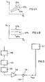
- FIG. 4 shows a simplified version of FIG. 3.
- FIG. 4 again shows the inlet and outlet measuring elements 9.1 and 9.2, the pre-delay field 11, the main delay field 12 and the computer 10 with its inputs for the signals R x , C x , A should , A out , 1 T and 1 in .
- This figure highlights the fact that all rule operations are implemented in the software of the computer, ie the "elements" of paths 1 to 4 of FIG. 3 are aspects of the programming of the computer 10.
- the size m e should correspond to the mass of the fibers located in the measuring field of the inlet measuring element 9.1.
- the individual signal components R x and C x do not correspond to this mass because they are also dependent on at least one further variable (the "parameter”). However, it is possible to create a "family” for this important parameter. of “curves” which determine the course of the two signal components R and C as a function of the fiber mass (ie as a function of m e ) for any selected values of the parameter. This has been done in the diagrams 4A (signal component C x ) and 4B (signal component R x ), which is not about the exact course of the characteristics, but only about the representation of the principle.
- the parameter is the water content of the fiber structure, which can be represented, for example, as a percentage of the fiber mass. As examples, three characteristics are shown in FIGS. 4A and 4B - one characteristic at 10% water, one characteristic at 20% water and one characteristic at 30% water.
- FIG. 4B shows horizontal "curves" in FIG. 4B, which is not entirely true in practice, but can be assumed as an approximation.
- a signal component pair R x , C x can be uniquely assigned to any value of m e (fiber mass in the measuring field).
- the “real” signal component R enables “selection” from the “curves” in FIG. 4A, so that the “imaginary” signal component can be used to determine the fiber mass (size m e ) on the basis of the relevant characteristic.
- the system Before cleaning the map, which will be described below, the system will not work optimally, since the map, which is largely theoretically formed, will hardly meet the practical conditions.
- the preferred outlet measuring element is a pair of sensing rollers, for example according to our US Pat. No. 4,539,729.
- This reconstructed value of the fiber mass in the feed tape is assigned (as the size m e ) in the characteristic diagram to the appropriate signal component pair, the originally (theoretically) calculated value of the size m e for this signal component pair being canceled.
- the system After a certain period of "experience", the system has built up its own (tailored) map in this way and can work “optimized” accordingly. However, only a single “disruptive factor” (the water content of the supply belt) has been taken into account.
- the disturbances include, for example, changes in air humidity which influence the "stretchability" of the fiber structure and the delivery speed, which can influence the behavior of the control loop.
- the changeable variable as a "parameter” and to create a separate map for different values of this parameter. It is then from one map to another depending on, for example, a signal on input 1 changed in or from the setting of delivery speed.
- the inlet measuring element supplies two signal components that can be clearly assigned as a pair to a determinable fiber mass and that the determination can be carried out on the basis of the signal supplied by the outlet measuring element and known or ascertainable parameters of the controlled system.
- Fig. 4 therefore shows one way to effect this division.
- An alternating current source Q supplies energy with a predetermined frequency to the capacitor and also to the rectifier 102, 104 wherein a rectifier 102 is in phase and a rectifier 104 is fed with a 90 ° phase shift with respect to the capacitor.
- Rectifier 104 provides a signal representing 1 / R x and rectifier 102 provides its signal to an addition element 110, where it is compared with a reference value Co is combined, which corresponds to the capacitance of the "empty" capacitor (ie without sliver).
- the output line of this element 110 carries the signal C x in the form of deviations from the reference value.
- the description so far has focused on the advantages of the new system that arise in connection with the "admixing" of a disturbing material (water) in the fiber structure. But even if the fiber structure to be scanned only contains fibers (and air), the new system can offer an additional advantage, namely if the inlet measuring element cannot provide absolute values in itself but only relative results. This is e.g. the case where the inlet measuring element is formed as a measuring capacitor (Fig. 2).
- the outlet measuring element 9.2 plays an important role both in the regulation (path 3, FIG. 3) for keeping the mean value of the delivered strip constant and in the control (path 1, 2 and 4, FIG. 3) for compensating for short-wave fluctuations in mass. While the inlet measuring element has to react to a “fleece” (FIG. 2), the outlet measuring element can be placed at a measuring point after the stretched nonwoven has been combined into a band (in funnel T, FIG. 1).
- a pair of sensing rollers in the outlet, which reacts to the cross-section of the tape supplied.
- a pair of sensing rollers is practically insensitive to the water content of the belt.
- This type of transducer is therefore ideally suited to suppressing measurement errors caused by moisture in the inlet measuring element via the map.
- a measuring sensor that reacts to the strip cross section is subject to its own measuring errors, which must also be taken into account. The main error in measuring the cross-section of the strip is caused by the air entrained by fibers inside the strip.
- Fluctuations in the amount of entrained air are due to changes in the packing density of the fibers in the belt, ie changes in the space between the fibers.
- the amount of air in the fiber structure during measurement also depends on how much air was squeezed out when the fiber structure was compressed. Both the packing density and the resistance which resists the squeezing of air depend essentially on the degree of parallelization of the fibers.
- the degree of parallelization of the fibers in a belt supplied by a drafting system depends on the one hand on the degree of parallelization of the fibers in the feed material and on the other hand on the distortion exerted in the drafting system. Since the warping in a regulating drafting system changes constantly, the packing density of the fibers in the delivered belt can be changed and therefore a variable amount of air in the belt cross section can be expected.
- a correction of the output signal of the outlet measuring element should be carried out at least in the event of high distortion changes in order to eliminate the effects of the variable amount of distortion on the signal level.
- This can easily be carried out by the computer 10 (FIGS. 3 and 4) because this computer receives the corresponding information about the amount of delay (with a suitable time shift, link Z3, FIG. 3).
- FIG. 5 schematically shows a "hardware solution” which, however, could also be implemented by programming the computer 10.
- This solution comprises a "signal generator” 120 (eg element 43, FIG. 3) which delivers a signal dependent on the delay to a time shift element 122 (eg element Z3, FIG. 3).
- the time-shifted signal is forwarded to a threshold value element 124, so that when the threshold value, which corresponds to a predetermined amount of delay, is exceeded, a correction signal is passed on to the addition point 128 via an amplifier 126.
- the addition point 128 also receives the output signal A out of the outlet measuring device 9.2 and sums this signal with the correction signal when the latter is received by amplifier 126. The result is passed on to paths 1, 2, 3 and 4 via output 130 for evaluation. If no correction signal is generated because the threshold value determined by the element 124 has not been exceeded, the addition point 128 forwards the signal A out via the output 130 without correction.
- the degree of parallelization of the fibers in the delivered tape depends not only on the amount of warping applied but also on the degree of parallelization of the fibers in the original material. This increases steadily in the spinning line from the card to the final spinning process. Accordingly, the correction of the output signal of the outlet measuring device becomes more important the earlier the regulating drafting device is used in the processing line - and the appropriate correction also depends on this "environmental factor”. It is therefore advantageous in practice to make the amplifier 126 adjustable so that the correction signal can be adapted at this point in the processing line.
- threshold switch 124 It is not absolutely necessary to provide the threshold switch 124. A signal dependent on the amount of delay can be continuously supplied to the amplifier 126, so that the signal A out is always corrected as a function of the amount of delay. Two or more threshold values could also be defined that produce different corrections, the corrections being known empirical values.
- the correction can be avoided by correcting the output signal of the outlet measuring element as a function of the current delivery speed (at least during braking or ramp-up).
- the correction has not been shown individually in FIG. 5, since it can be carried out essentially as for the distortion correction shown.
- the correction signal is of course not derived from the delay but from the delivery speed and sent to a suitable point (e.g. the addition point 128) for combination with the output signal from the measuring element 9.2.
Landscapes
- Engineering & Computer Science (AREA)
- Mechanical Engineering (AREA)
- Textile Engineering (AREA)
- Spinning Or Twisting Of Yarns (AREA)
- Preliminary Treatment Of Fibers (AREA)
Claims (5)
- Procédé pour la correction d'un signal de mesure déterminé pour la masse d'un ruban de fibres d'un banc d'étirage autorégulateur pour des rubans de fibres (15.1-15.6) comportant un organe de mesure de sortie (9.2), au moins un champ d'étirage (11, 12), un système d'entraînement (7.1, 7.2) et une commande respectivement une régulation (8.1, 8.2) pour le système d'entraînement, la commande respectivement la régulation réagissant à un signal de mesure (Aout) fourni par l'organe de mesure de sortie (9.2) afin de changer l'étirage dans le champ d'étirage mentionné de telle sorte que des variations de masse dans les rubans d'alimentation (15.1-15.6) sont corrigées, caractérisé en ce que le signal de mesure (Aout) de l'organe de mesure de sortie (9.2) est saisi dans une unité calculatrice (10); en ce que les valeurs relatives à l'intensité de l'étirage et à la vitesse de livraison sont introduites dans l'unité calculatrice (10) et que l'unité calculatrice (10) corrige le signal de mesure (Aout) en fonction de l'intensité de l'étirage et de la vitesse de livraison si bien que l'unité calculatrice (10) peut corriger un champ caractéristique ( R ) mémorisé de l'élément (50) du champ caractéristique afin de compenser les effets de l'intensité de l'étirage et de la vitesse de livraison sur le signal de mesure (Aout) de l'organe de mesure de sortie (9.2).
- Procédé selon la revendication 1 caractérisé en ce que l'organe de mesure de sortie (9.2) convient pour la détermination de la section du ruban fourni.
- Procédé selon une des revendications 1 à 2, un organe de mesure (9.1) supplémentaire étant disposé en amont du banc d'étirage, dans (le champ de) l'alimentation, organe de mesure qui réagit à la masse du ruban de fibres alimenté (15.1-15.6) et à la quantité d'une matière (ou d'un milieu) entraînée avec la masse du ruban de fibres, caractérisé en ce que des moyens pour l'obtention d'un composant (me) représentatif pour la masse du ruban de fibres sont prévus et que ce composant (me) est attribué au résultat de mesure de la masse du ruban de fibres déterminée dans l'organe de mesure de sortie (9.2) pour la régulation du système d'entraînement, l'organe de mesure (9.2) disposé à la sortie ne réagissant pas à la matière ( resp. au milieu) entraînée.
- Procédé selon la revendication 1 ou 3, caractérisé en ce que les signaux de mesure (Aout) fournis par l'organe de mesure (9.2) de la sortie sont conduits vers un élément de correction (128) auquel sont transmis les signaux de correction saisis par des éléments de saisie prévus sur le banc d'étirage autorégulateur, conformément aux conditions de service déterminées en permanence, aux fins de correction du signal de mesure (Aout).
- Procédé selon la revendication 4, caractérisé en ce que le transfert de signaux de correction se basant sur les conditions de service déterminées, est commandé par un élément seuil (124) disposé en amont de l'élément de correction (128).
Applications Claiming Priority (2)
| Application Number | Priority Date | Filing Date | Title |
|---|---|---|---|
| CH3100/90 | 1990-09-26 | ||
| CH310090 | 1990-09-26 |
Publications (2)
| Publication Number | Publication Date |
|---|---|
| EP0477589A1 EP0477589A1 (fr) | 1992-04-01 |
| EP0477589B1 true EP0477589B1 (fr) | 1996-04-24 |
Family
ID=4248624
Family Applications (1)
| Application Number | Title | Priority Date | Filing Date |
|---|---|---|---|
| EP91114720A Expired - Lifetime EP0477589B1 (fr) | 1990-09-26 | 1991-09-02 | Procédé pour la correction d'un signal de mesure déterminé pour la masse d'un ruban de carde d'un régulateur d'étirage pour des rubans de carde avec un organe de mesure de sortie |
Country Status (4)
| Country | Link |
|---|---|
| US (1) | US5394591A (fr) |
| EP (1) | EP0477589B1 (fr) |
| JP (1) | JPH04245931A (fr) |
| DE (1) | DE59107714D1 (fr) |
Cited By (2)
| Publication number | Priority date | Publication date | Assignee | Title |
|---|---|---|---|---|
| DE10236778A1 (de) * | 2002-08-10 | 2004-02-19 | Rieter Ingolstadt Spinnereimaschinenbau Ag | Verfahren und Vorrichtung zum Verstrecken von mindestens eines Faserband |
| DE10335856A1 (de) * | 2003-08-06 | 2005-03-03 | Rieter Ingolstadt Spinnereimaschinenbau Ag | Verfahren und Vorrichtung zum Messen der Bandmasse und/oder der Bandmasseschwankungen eines laufenden Faserverbandes sowie Spinnereivorbereitungsmaschine mit einer Messvorrichtung |
Families Citing this family (16)
| Publication number | Priority date | Publication date | Assignee | Title |
|---|---|---|---|---|
| DE4306343C1 (de) * | 1993-02-25 | 1994-07-14 | Grosenhainer Textilmaschbau | Verfahren zur Vergleichmäßigung von textilen Faserbändern |
| DE4441067A1 (de) * | 1993-12-20 | 1995-06-22 | Truetzschler Gmbh & Co Kg | Regulierstreckwerk für Faserbänder an einer Strecke mit einem Einlaufmeßorgan |
| US6581248B1 (en) * | 1997-01-23 | 2003-06-24 | Maschinenfabrik Rieter Ag | Carding machine with drawing rollers at the outlet |
| DE19822886B4 (de) * | 1997-07-01 | 2007-03-29 | TRüTZSCHLER GMBH & CO. KG | Regulierstreckwerk für einen Faserverband, z. B. Baumwolle, Chemiefasern o. dgl. mit mindestens einem Verzugsfeld |
| DE59804686D1 (de) * | 1997-09-01 | 2002-08-08 | Rieter Ag Maschf | Reguliertes streckwerk |
| DE19921429B4 (de) * | 1998-06-29 | 2017-03-02 | Rieter Ingolstadt Gmbh | Verfahren und Vorrichtung zur Fehlerkorrektur eines von einem Meßorgan gelieferten Meßwertes von Faserband in einer Textilmaschine |
| DE19908371A1 (de) * | 1999-02-26 | 2000-08-31 | Truetzschler Gmbh & Co Kg | Vorrichtung an einer Strecke zur Verarbeitung eines Faserverbandes aus Faserbändern |
| AU2001295484A1 (en) * | 2000-08-23 | 2002-03-04 | Rieter Ingolstadt Spinnereimaschinenbau Ag | Method for operating drawing equipment and drawing equipment |
| DE10057699A1 (de) * | 2000-11-21 | 2002-05-23 | Truetzschler Gmbh & Co Kg | Vorrichtung an einer Strecke zur Verarbeitung von Faserbändern, z. B. Baumwolle, Chemiefasern u. dgl. |
| DE10060227A1 (de) * | 2000-12-04 | 2002-06-13 | Truetzschler Gmbh & Co Kg | Vorrichtung am Ausgang einer Strecke zur Erfassung des Fasergutes |
| CN1287019C (zh) * | 2001-02-16 | 2006-11-29 | 特鲁菲舍尔股份有限公司及两合公司 | 在纤维条的自调匀整针梳机上用于测定预拉伸调定值的方法和装置 |
| DE10153999B4 (de) * | 2001-11-02 | 2011-07-14 | Rieter Ingolstadt GmbH, 85055 | Simulationsverfahren für eine Spinnereimaschine, Spinnereimaschine, sowie Softwareprogamm-Erzeugnis |
| CN100451195C (zh) * | 2001-12-19 | 2009-01-14 | 特鲁菲舍尔股份有限公司及两合公司 | 测定前端扭曲的调整值的装置 |
| DE10214955B9 (de) * | 2002-04-04 | 2017-06-29 | Rieter Ingolstadt Gmbh | Spinnereivorbereitungsmaschine |
| DE102013113308A1 (de) * | 2013-12-02 | 2015-06-03 | Rieter Ingolstadt Gmbh | Textilmaschine mit variablem Anspannverzug |
| CN111058132A (zh) * | 2020-01-06 | 2020-04-24 | 北京经纬纺机新技术有限公司 | 并条匀整死区精确测量系统及测量方法 |
Family Cites Families (26)
| Publication number | Priority date | Publication date | Assignee | Title |
|---|---|---|---|---|
| US2950508A (en) * | 1954-12-31 | 1960-08-30 | Zellweger Uster Ag | Method and apparatus for automatically controlling the weight per unit length of textile materials |
| US2930084A (en) * | 1955-10-28 | 1960-03-29 | Bates Mfg Co | Apparatus for corrective drafting of strands of discontinuous fibers |
| GB824070A (en) * | 1956-10-18 | 1959-11-25 | Fielden Electronics Ltd | Improvements relating to textile drafting eqipment |
| NL99739C (fr) * | 1958-01-09 | |||
| US3088175A (en) * | 1958-01-10 | 1963-05-07 | Aoki Akira | Automatic level control system for product sliver weight |
| CH557429A (de) * | 1972-10-30 | 1974-12-31 | Zellweger Uster Ag | Verfahren und vorrichtung zur vergleichmaessigung von kaemmaschinenbaendern. |
| US3925850A (en) * | 1973-11-01 | 1975-12-16 | Fibers Controls Corp | Density sensing and controlling equipment |
| CH571072A5 (fr) * | 1974-02-28 | 1975-12-31 | Zellweger Uster Ag | |
| US4163927A (en) * | 1977-05-04 | 1979-08-07 | Fiber Controls Corporation | Auto-leveler circuit |
| DE2911378A1 (de) * | 1979-03-23 | 1980-10-02 | Zinser Textilmaschinen Gmbh | Ringspinn- oder ringzwirnmaschine |
| CS210918B1 (en) * | 1979-09-27 | 1982-01-29 | Vojtech Smajstrla | Fault remedy at control of sliver density on textile machines |
| DE2941612A1 (de) * | 1979-10-13 | 1981-04-23 | Zinser Textilmaschinen Gmbh, 7333 Ebersbach | Strecke |
| GB2081758B (en) * | 1980-08-12 | 1984-02-22 | Le Nii Textilnoi | Regulating apparatus for automatically controlling the evenness of the linear density of a silver |
| DE3120133C2 (de) * | 1981-05-20 | 1985-05-09 | Trützschler GmbH & Co KG, 4050 Mönchengladbach | Vorrichtung zur Regelung und Steuerung einer Karde oder Krempel |
| EP0078393B1 (fr) * | 1981-10-29 | 1986-05-14 | Maschinenfabrik Rieter Ag | Dispositif pour la compression ou la détection continue de la masse d'un ruban de fibres textiles |
| DE3205880A1 (de) * | 1982-02-18 | 1983-08-25 | Zinser Textilmaschinen Gmbh, 7333 Ebersbach | Streckwerk fuer eine spinnereimaschine |
| DE3472805D1 (en) * | 1983-09-05 | 1988-08-25 | Chubu Seiko Kk | Device for automatically controlling the draft in a spinning machine |
| CH668781A5 (de) * | 1984-09-25 | 1989-01-31 | Zellweger Uster Ag | Verfahren und vorrichtung zur optimierung des streckprozesses bei regulierstrecken der textilindustrie. |
| DE3703450A1 (de) * | 1986-05-24 | 1987-11-26 | Truetzschler & Co | Verfahren und vorrichtung zur vergleichmaessigung des faserbandes bei einer karde |
| DE3619248A1 (de) * | 1986-06-07 | 1987-12-10 | Zinser Textilmaschinen Gmbh | Verfahren zur steuerung des verzugs eines faserbandes bei einer textilmaschine |
| IT1227771B (it) * | 1986-07-04 | 1991-05-06 | Zinser Textilmaschinen Gmbh | Procedimento e dispositivo per regolare lo stiro di un nastro di fibre in una macchina tessile. |
| DE3635341A1 (de) * | 1986-10-17 | 1988-04-28 | Zinser Textilmaschinen Gmbh | Vorrichtung zur regulierung des verzugs eines faserbands bei einer textilmaschine |
| IN172476B (fr) * | 1988-02-12 | 1993-08-21 | Rieter Ag Maschf | |
| DE3815200C2 (de) * | 1988-05-04 | 1998-01-29 | Truetzschler Gmbh & Co Kg | Verfahren und Vorrichtung zur Überwachung des Vergleichmäßigens mindestens eines Faserverbandes in einem Regulierstreckwerk |
| EP0412448B1 (fr) * | 1989-08-11 | 2000-10-11 | Maschinenfabrik Rieter Ag | Système d'étirage avec commande maillée |
| US4974296A (en) * | 1990-02-23 | 1990-12-04 | Platt Saco Lowell Corporation, Inc. | Apparatus for correcting irregularities in a textile strand |
-
1991
- 1991-09-02 EP EP91114720A patent/EP0477589B1/fr not_active Expired - Lifetime
- 1991-09-02 DE DE59107714T patent/DE59107714D1/de not_active Expired - Fee Related
- 1991-09-25 US US07/765,570 patent/US5394591A/en not_active Expired - Fee Related
- 1991-09-26 JP JP3247249A patent/JPH04245931A/ja active Pending
Cited By (3)
| Publication number | Priority date | Publication date | Assignee | Title |
|---|---|---|---|---|
| DE10236778A1 (de) * | 2002-08-10 | 2004-02-19 | Rieter Ingolstadt Spinnereimaschinenbau Ag | Verfahren und Vorrichtung zum Verstrecken von mindestens eines Faserband |
| DE10236778B4 (de) * | 2002-08-10 | 2011-05-05 | Rieter Ingolstadt Gmbh | Verfahren und Vorrichtung zum Verstrecken von mindestens eines Faserband |
| DE10335856A1 (de) * | 2003-08-06 | 2005-03-03 | Rieter Ingolstadt Spinnereimaschinenbau Ag | Verfahren und Vorrichtung zum Messen der Bandmasse und/oder der Bandmasseschwankungen eines laufenden Faserverbandes sowie Spinnereivorbereitungsmaschine mit einer Messvorrichtung |
Also Published As
| Publication number | Publication date |
|---|---|
| JPH04245931A (ja) | 1992-09-02 |
| DE59107714D1 (de) | 1996-05-30 |
| EP0477589A1 (fr) | 1992-04-01 |
| US5394591A (en) | 1995-03-07 |
Similar Documents
| Publication | Publication Date | Title |
|---|---|---|
| EP0477589B1 (fr) | Procédé pour la correction d'un signal de mesure déterminé pour la masse d'un ruban de carde d'un régulateur d'étirage pour des rubans de carde avec un organe de mesure de sortie | |
| EP0412448B1 (fr) | Système d'étirage avec commande maillée | |
| EP1086264B1 (fr) | Banc d'etirage de regulation | |
| EP0587829B1 (fr) | Procede et dispositif de regulation de l'etirage dans un banc d'etirage | |
| WO1993012278A1 (fr) | Peigneuse | |
| CH683535A5 (de) | Streckwerkantrieb. | |
| EP1009870B2 (fr) | Banc d'etirage regule | |
| EP2034059B1 (fr) | Procédé de détermination du poids lineaire d'un ruban de fibres et machine de préparation de filature | |
| CH699640B1 (de) | Verfahren zur Steuerung des Verzugs eines Streckwerks einer Textilmaschine sowie Textilmaschine. | |
| CH691382A5 (de) | Regulierstreckwerk für Faserbänder an einer Strecke mit einem Einlaufmessorgan. | |
| EP0978581B1 (fr) | Machine pour le traitement de matériau textile avec banc d'étirage | |
| DE102005019760B4 (de) | Spinnereimaschine mit einem Streckwerk zum Verstrecken eines Faserverbandes und entsprechendes Verfahren | |
| DE1921248A1 (de) | Verfahren und Vorrichtung zur Vergleichmaessigung von Kardenbaendern | |
| EP0502137A1 (fr) | Banc d'etirage avec cylindre de sortie regule | |
| CH696121A5 (de) | Vorrichtung an einem Streckwerk für Faserbänder, z.B. einer Strecke, zum Ermitteln von Einstellwerten für den Vorverzug. | |
| EP0678601A2 (fr) | Banc d'étirage contrôlé | |
| DE3937439A1 (de) | Verfahren und vorrichtung zum bestimmen von wartungsintervallen an einer spinnereimaschine | |
| EP0411379B1 (fr) | Dispositif d'étirage ayant des groupes de commande contrôlés | |
| DE102004007143B4 (de) | Verfahren und Vorrichtung zum Verstrecken von mindestens einem Faserband | |
| CH695295A5 (de) | Vorrichtung an einer Regulierstrecke fuer Fasermaterial zum direkten Ermitteln von Einstellwerten fuer den Reguliereinsatzpunkt. | |
| EP3719186A1 (fr) | Procédé de fonctionnement d'une machine textile ainsi que machine textile | |
| CH695296A5 (de) | Vorrichtung an einer Regulierstrecke fuer Faserbaender zum direkten Ermitteln von Einstellwerten fuer den Reguliereinsatzpunkt. | |
| DE102005037124A1 (de) | Verfahren zur Steuerung des Verzugs eines Verzugsfeldes einer Textilmaschine sowie Textilmaschine | |
| DE1043886B (de) | Verfahren und Vorrichtung zum selbsttaetigen Regeln des Verzuges des Faserbandes in Streckwerken od. dgl. | |
| EP2578731B1 (fr) | Procédé destiné à corriger une grandeur caractéristique dépendant de l'épaisseur de bande d'un ruban de fibre ainsi que machine textile correspondante dotée d'un dispositif d'étirement d'un ruban de fibre |
Legal Events
| Date | Code | Title | Description |
|---|---|---|---|
| PUAI | Public reference made under article 153(3) epc to a published international application that has entered the european phase |
Free format text: ORIGINAL CODE: 0009012 |
|
| 17P | Request for examination filed |
Effective date: 19911210 |
|
| AK | Designated contracting states |
Kind code of ref document: A1 Designated state(s): CH DE FR GB IT LI |
|
| 17Q | First examination report despatched |
Effective date: 19930915 |
|
| GRAA | (expected) grant |
Free format text: ORIGINAL CODE: 0009210 |
|
| AK | Designated contracting states |
Kind code of ref document: B1 Designated state(s): CH DE FR GB IT LI |
|
| PG25 | Lapsed in a contracting state [announced via postgrant information from national office to epo] |
Ref country code: GB Effective date: 19960424 Ref country code: FR Effective date: 19960424 |
|
| REF | Corresponds to: |
Ref document number: 59107714 Country of ref document: DE Date of ref document: 19960530 |
|
| ITF | It: translation for a ep patent filed | ||
| EN | Fr: translation not filed | ||
| GBV | Gb: ep patent (uk) treated as always having been void in accordance with gb section 77(7)/1977 [no translation filed] |
Effective date: 19960424 |
|
| PLBI | Opposition filed |
Free format text: ORIGINAL CODE: 0009260 |
|
| 26 | Opposition filed |
Opponent name: TRUETZSCHLER GMBH & CO.KG Effective date: 19961213 |
|
| PLBF | Reply of patent proprietor to notice(s) of opposition |
Free format text: ORIGINAL CODE: EPIDOS OBSO |
|
| PLBF | Reply of patent proprietor to notice(s) of opposition |
Free format text: ORIGINAL CODE: EPIDOS OBSO |
|
| PLBO | Opposition rejected |
Free format text: ORIGINAL CODE: EPIDOS REJO |
|
| APAC | Appeal dossier modified |
Free format text: ORIGINAL CODE: EPIDOS NOAPO |
|
| APAE | Appeal reference modified |
Free format text: ORIGINAL CODE: EPIDOS REFNO |
|
| APAC | Appeal dossier modified |
Free format text: ORIGINAL CODE: EPIDOS NOAPO |
|
| APAE | Appeal reference modified |
Free format text: ORIGINAL CODE: EPIDOS REFNO |
|
| APAC | Appeal dossier modified |
Free format text: ORIGINAL CODE: EPIDOS NOAPO |
|
| PLBN | Opposition rejected |
Free format text: ORIGINAL CODE: 0009273 |
|
| STAA | Information on the status of an ep patent application or granted ep patent |
Free format text: STATUS: OPPOSITION REJECTED |
|
| 27O | Opposition rejected |
Effective date: 20000713 |
|
| PG25 | Lapsed in a contracting state [announced via postgrant information from national office to epo] |
Ref country code: IT Free format text: LAPSE BECAUSE OF NON-PAYMENT OF DUE FEES;WARNING: LAPSES OF ITALIAN PATENTS WITH EFFECTIVE DATE BEFORE 2007 MAY HAVE OCCURRED AT ANY TIME BEFORE 2007. THE CORRECT EFFECTIVE DATE MAY BE DIFFERENT FROM THE ONE RECORDED. Effective date: 20050902 |
|
| PGFP | Annual fee paid to national office [announced via postgrant information from national office to epo] |
Ref country code: DE Payment date: 20050912 Year of fee payment: 15 |
|
| PGFP | Annual fee paid to national office [announced via postgrant information from national office to epo] |
Ref country code: CH Payment date: 20050915 Year of fee payment: 15 |
|
| APAH | Appeal reference modified |
Free format text: ORIGINAL CODE: EPIDOSCREFNO |
|
| PG25 | Lapsed in a contracting state [announced via postgrant information from national office to epo] |
Ref country code: LI Free format text: LAPSE BECAUSE OF NON-PAYMENT OF DUE FEES Effective date: 20060930 Ref country code: CH Free format text: LAPSE BECAUSE OF NON-PAYMENT OF DUE FEES Effective date: 20060930 |
|
| PG25 | Lapsed in a contracting state [announced via postgrant information from national office to epo] |
Ref country code: DE Free format text: LAPSE BECAUSE OF NON-PAYMENT OF DUE FEES Effective date: 20070403 |
|
| REG | Reference to a national code |
Ref country code: CH Ref legal event code: PL |