EP0476672A1 - Dispositif pour retenir verrouillé un revêtement routier sur un caniveau d'écoulement - Google Patents
Dispositif pour retenir verrouillé un revêtement routier sur un caniveau d'écoulement Download PDFInfo
- Publication number
- EP0476672A1 EP0476672A1 EP91115976A EP91115976A EP0476672A1 EP 0476672 A1 EP0476672 A1 EP 0476672A1 EP 91115976 A EP91115976 A EP 91115976A EP 91115976 A EP91115976 A EP 91115976A EP 0476672 A1 EP0476672 A1 EP 0476672A1
- Authority
- EP
- European Patent Office
- Prior art keywords
- locking
- cover
- component
- locking device
- inclined surface
- Prior art date
- Legal status (The legal status is an assumption and is not a legal conclusion. Google has not performed a legal analysis and makes no representation as to the accuracy of the status listed.)
- Granted
Links
Images


Classifications
-
- E—FIXED CONSTRUCTIONS
- E01—CONSTRUCTION OF ROADS, RAILWAYS, OR BRIDGES
- E01C—CONSTRUCTION OF, OR SURFACES FOR, ROADS, SPORTS GROUNDS, OR THE LIKE; MACHINES OR AUXILIARY TOOLS FOR CONSTRUCTION OR REPAIR
- E01C11/00—Details of pavings
- E01C11/22—Gutters; Kerbs ; Surface drainage of streets, roads or like traffic areas
- E01C11/224—Surface drainage of streets
- E01C11/227—Gutters; Channels ; Roof drainage discharge ducts set in sidewalks
-
- E—FIXED CONSTRUCTIONS
- E03—WATER SUPPLY; SEWERAGE
- E03F—SEWERS; CESSPOOLS
- E03F5/00—Sewerage structures
- E03F5/04—Gullies inlets, road sinks, floor drains with or without odour seals or sediment traps
- E03F5/06—Gully gratings
-
- E—FIXED CONSTRUCTIONS
- E03—WATER SUPPLY; SEWERAGE
- E03F—SEWERS; CESSPOOLS
- E03F5/00—Sewerage structures
- E03F5/04—Gullies inlets, road sinks, floor drains with or without odour seals or sediment traps
- E03F5/06—Gully gratings
- E03F2005/065—Gully gratings with elastic locking elements
-
- Y—GENERAL TAGGING OF NEW TECHNOLOGICAL DEVELOPMENTS; GENERAL TAGGING OF CROSS-SECTIONAL TECHNOLOGIES SPANNING OVER SEVERAL SECTIONS OF THE IPC; TECHNICAL SUBJECTS COVERED BY FORMER USPC CROSS-REFERENCE ART COLLECTIONS [XRACs] AND DIGESTS
- Y02—TECHNOLOGIES OR APPLICATIONS FOR MITIGATION OR ADAPTATION AGAINST CLIMATE CHANGE
- Y02A—TECHNOLOGIES FOR ADAPTATION TO CLIMATE CHANGE
- Y02A30/00—Adapting or protecting infrastructure or their operation
- Y02A30/60—Planning or developing urban green infrastructure
Definitions
- the invention relates to a device for locking a drivable cover on a drainage channel, a drain or similar component according to the preamble of claim 1.
- Drainage channels, supply or cable channels, gullies or the like are generally closed by covers, so that (pedestrian or driving) traffic is not hindered. Such covers must now sit very securely on the component and be connected to it so that there is no danger to traffic. Especially when the covered component is installed on a street or on a factory site, the connection between the cover and the component must withstand very high loads. If, for example, you look at the almost shock-like alternating loads caused by a fast-moving car or even a heavily loaded truck when driving over it, or include the (additional) loads that occur when braking, it becomes clear that the cover is carefully attached to the component must be thought out.
- a locking device for covering a drainage channel or similar component which is considerably easier to handle is known from EP 0 081 741 C1.
- a threaded bolt leading through the cover is also provided, which sits in a threaded hole of a crossbar.
- the cross-beam is dimensioned so that when the cover is put on it can initially be positioned essentially in the longitudinal direction of the channel, in order to then be able to snap it into recesses in the inner wall of the channel which are open on one side, and then when the screw is turned further Bolt the ends of the crossbar to the upper end surfaces of the openings and the cover can be tightened. Due to the high loads described above, in particular due to the alternating loads, however, the connection can loosen over time. In addition, this solution also has a screw connection which can corrode over time with the described disadvantageous consequences.
- the invention has for its object to develop a device of the type mentioned in such a way that increased security is achieved with simple means at the same time as easier handling.
- An essential point of the invention is that by the combination of (at least) an inclined surface on a locking part and a movable locking piece which is acted upon in the closing direction, movements of the cover - and thus of the locking piece - do not loosen the connection but rather tighten it.
- This automatic re-tensioning of the connecting device keeps the cover securely on the component even if material deformation or wear occurs.
- the basic idea of the invention is already realized by a device in which there is only one locking part with an inclined surface, under which the locking piece is seated.
- two locking parts are provided, one on the component and one on the cover, the inclined surfaces of which are inclined in the same direction, so that a gap is formed between them which closes when the cover is lifted off the component.
- the locking part then sits between the inclined surfaces, that is to say in the gap, so that the two locking parts can no longer be displaced relative to one another in the vertical direction.
- the inclined surfaces are preferably designed such that that the gap converges downwards.
- the tensioning effect is particularly great when the locking piece is essentially circular at least in the area of the inclined surfaces. This makes it particularly easy to move down in the gap until it comes into engagement with the upper inclined surface. Nevertheless, a sufficiently large clamping effect occurs when the cover is lifted up.
- the locking parts are preferably arranged in pairs opposite one another. When used on a circular lid, the locking parts are diametrically opposed to each other. When used in connection with a drainage channel, a supply or cable duct or the like elongated component, the locking parts are located on the side edges of the component, preferably a pair at one end and a pair at the other end.
- the handling of the device when opening and the manufacture of the device are particularly simple in this case, since a single locking piece can be used for a pair of locking parts - each locking part possibly having two inclined surfaces - the two ends of which each lock a locking part .
- the locking piece is preferably designed as a removable, ie individually manageable part, so that when the locking part has been removed from the gap between the inclined surfaces, the cover can be easily lifted off.
- fixing devices are provided and attached in such a way that the locking piece can be kept out of engagement with the inclined surfaces (or with the inclined surface) without having to remove it entirely.
- This metal element can now either be retrofitted into the component (made of concrete) or cast in with it. This solution will be chosen especially if the load capacity is not too high.
- the metal element has a bearing surface for the cover at the same time, that is, it forms a frame on the upper edge of the component.
- a bearing surface for the cover at the same time, that is, it forms a frame on the upper edge of the component.
- the support surface can be brought into engagement with the cover essentially in a form-fitting manner, the signs of wear on all components that can be moved relative to one another are reduced, and the security of the connection is thus increased.
- the locking piece must be removed from the gap or removed from under the inclined surface in order to lift the cover.
- latching recesses which are open at the top and which are seated in a component connected to the cover can be provided as fixing devices.
- the locking piece can then be hooked into these recesses.
- Such a locking recess is preferably located above the upper end of the gap.
- the fixing device is designed as a separately manageable fixing part, by means of which the locking part can be kept out of engagement with the inclined surface (s).
- the fixing device is therefore only used if necessary - for lifting the cover - or brought into a corresponding position.
- one is suitable as the fixing part which has an upwardly open latching recess in which the locking piece can be received.
- the inclined surfaces run relative to an inner wall of the component if they only point obliquely downwards.
- the inclined surfaces can thus protrude perpendicularly from the inner wall of the component, as well as run parallel to the inner wall or be attached at an intermediate angle.
- a crossbar is attached to the underside of the cover, which is formed as a band perpendicularly downwards.
- the lower edges form the second inclined surface.
- the first locking part is designed as a band-shaped body which projects inwards from the side wall of the component. This band is angled so that its lower surface forms a downwardly converging gap with the lower edge of the recess.
- the band-shaped body is preferably fastened to a (likewise band-shaped) holding piece which is inserted into a side wall of the component.
- the component therefore has a corresponding slot.
- the holding piece is preferably designed as a cross member, the ends of which are each seated in a side wall of the component. This results in a simple structure with sufficient durability.
- the first locking part can be designed as a recess below the contact surface for the cover.
- the recess is preferably arranged in a reinforcing frame.
- the lower edge of the recess is formed by a boundary surface which slopes outwards (towards the interior of the component), that is to say is inclined downwards. Dirt particles, stones or the like falling into the recess therefore cannot be held.
- a reinforcement frame for example such as is described in EP 0 081 762 A1, is suitable.
- the cover is designed as a cast metal part, the attachment or formation of the second locking part is very difficult for casting reasons, since the necessary second inclined surface forms an undercut.
- the second locking part comprises a web, the upper edge of which forms the second inclined surface and which merges with one end or with both ends into the underside of the cover, the cover being open at the top in the region above the inclined surface .
- the sloping surface then no longer forms an undercut, but can be defined during casting by a core which projects through the opening in the cover.
- an adjusting device for. B. a notch or a nose are provided, which are then in positive engagement with each other when the cover sits directly on the component and can be locked.
- These adjustment devices are preferably attached symmetrically to a plane of symmetry which runs perpendicularly through the longitudinal axis of the component. It is therefore irrelevant which end of the cover comes to rest on which end of the gutter-shaped component body, which facilitates assembly.
- Another advantage of such an adjustment device is that forces acting on the cover in the direction of the longitudinal axis of the component can be absorbed by the adjustment devices.
- a pair of locking parts is provided in the region of the ends of the component or the cover, and these are likewise designed symmetrically with respect to the plane of symmetry.
- first inclined surfaces run essentially parallel to the inner wall of the component body (or to its upper edge)
- this embodiment of the invention ensures that the cover is held on the component with respect to forces in the longitudinal direction of the component, since the cover moves relatively to the component always leads to narrowing of a gap pair and pinching and the associated locking pieces.
- the inclined surfaces are preferably designed in such a way that the leading or front locking piece, seen in the direction of the force, is clamped more strongly when a force is applied in the longitudinal direction of the component. As a result, the cover is held particularly securely on the component even when such a force is applied.
- FIGS. 1-8 A first preferred embodiment of the invention is explained below with reference to FIGS. 1-8. Drainage channels are shown as exemplary embodiments. Of course, the invention is also applicable to other components with covers.
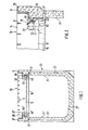
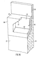
- FIGS. 1-8 The exemplary embodiment of the invention described in FIGS. 1-8 is a drainage channel for medium-heavy loads with a channel-shaped body made of polyester concrete which forms the component 20 and which has side walls 23 and a base 27. Its upper edge 25 is formed in such a way with an inner shoulder that a cross-sectionally, essentially Z-shaped frame 9 of a cover 10 can be inserted in a form-fitting manner.
- the cover 10 is designed in the form of a grid, with transverse webs 13 and longitudinal webs 8 being seated in the frame 19. Drain openings 14 are thus left free between the transverse webs 13 and the longitudinal webs 8.
- At least one transverse web 13 is provided at its ends with a gap 22 which converges inwards, forming an upper, essentially horizontal end surface and a lower, obliquely sloping surface 51.
- the inclined surface 51 merges into a latching recess 52, which essentially has a semicircular cross section.
- the inclined surface 51 of the gap 22 forms a locking part 50, the function of which is explained in more detail below.
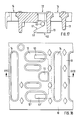
- a band-shaped holding piece 16 with its ends 17, 17 'is embedded in corresponding recesses in the side walls 23 of the component 20.
- the surface of the band-shaped holding piece 16 is thus parallel to the underside 11 of the cover 10.
- Band-shaped bodies 19 projecting vertically upward are welded onto the transverse web 13 in such a way that in a first section they run essentially parallel to the inner wall 21 of the component 20.
- the arrangement and the shape of the angled sections 18 are now such that the lower inclined surface 31 of the angled section 18 is inclined to the (upper) inclined surface 51 of the notch 22 to converge outwards.
- the column 22 defined by these two inclined surfaces 31 and 51 is thus inclined outwards, towards the respective side wall 23 and converges in this direction.
- the inclined surface 18 of the band-shaped body 19 thus forms a further locking part 30.
- a locking piece 40 is inserted with its ends 41, 41 '(Fig. 6), which have an essentially circular cross-section.
- the ends 41 of the locking piece thus sit in the tapered area of the notch 22 and are held there in firm contact with both the inclined surface 51 and the inclined surface 31 due to the dead weight of the locking element 40.
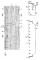
- This position is designated by the reference number 11 in FIG. 2.
- the band-shaped body 19, seen in the longitudinal direction of the component 20, is offset from the associated transverse web 13 (with a gap 22).
- the offset at the two ends of the component 20 is designed symmetrically to a plane of symmetry S, which runs perpendicular to the longitudinal axis of the component 20 in the center.
- a further measure for securing against horizontal displacements in the longitudinal direction of the component 20 and at the same time for the purpose of an exact adjustment of the inclined surfaces 31, 51 to one another is provided on the upper edge 25 of the component 20 lugs 26 which then engage in corresponding notches 15 in the frame 9 of the cover 10 when the cover 10 is placed correctly.
- the arrangement of the nose and notch can also be reversed. It is also important here that these adjustment devices 15, 16 are arranged symmetrically to the plane of symmetry S, so that the covering 10 can be placed on the component 20 without much thought.
- the drainage channel shown in FIGS. 1-8 thus consists of a total of only 4 pieces to be handled separately, namely the component 20 with the first locking parts 30 attached to it, the cover 10 with the second locking parts 50 formed thereon and two (identically shaped) locking pieces 40.
- the two locking pieces 40 are first inserted into the locking recesses 52 assigned to the second locking parts 50. Since the locking recesses 52, seen in cross section (see FIG. 2), lie outside the upper ends of the inclined surfaces 31, the cover 10 can now be put on. Then the locking pieces 40 with a suitable tool, for. B. with a screwdriver or even a stick from the locking recesses 52 and fall into the column 22. Thus, the cover 10 is permanently fixed on the component 20. The removal takes place in the reverse way and does not require any tools or skill.
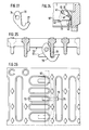
- a transverse web 13 ' according to FIG. 24 is provided with a gap 22' essentially in the middle between the two transverse webs 13 shown in FIG. 3, which has a downwardly projecting clamping lug 73 on its lower edge .
- the locking piece 40 In order to move the locking piece 40 upwards out of the clamping area and hold it there, it is pushed by means of an elongated instrument, e.g. B. by means of a screwdriver, the locking piece 40 with its cranked portion 42 such via the clamping lug 73 that it slips behind the surface facing the inside of the channel. This is possible due to the elasticity of the locking piece 40. In this way, the locking piece 40 is held in the position shown in FIG. 24. To unlock, you only have to press the cranked section 42 again in the opposite direction. In this embodiment, it cannot happen that the locking piece 40 accidentally jumps up due to impact loads and remains in the unlocked position.
- an elongated instrument e.g. B. by means of a screwdriver
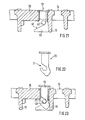
- the locking piece 40 is “movably attached” to the cover 10 indirectly, namely via the inclined surface 51 or the associated locking part 50.
- the locking piece 40 is attached directly to a cross piece 51 of the cover 10.
- the locking piece 40 has a shape, most clearly shown in FIG. 10, of a chain link which sits with an upper end in an elongated hole 7 extending from top to bottom in the crosspiece 53.
- a hook-shaped tab 54 protrudes perpendicularly from the latter.
- This has an opening which is open at the top and has a substantially triangular cross section, one leg of the cross section through the inner wall 21 of the component 20, the second leg, which is substantially perpendicular thereto, the lower edge of the opening, and the third which runs obliquely to the other two legs Edge forms the inclined surface 51.
- This component thus forms the locking device 50.
- the section of the inclined surface 51 facing the open upper end of this recess is designated by the reference number 51 in FIG. 5 and runs in the shape of a circular arc, the radius of the circular arc being determined by the length of the "chain link" 40 which forms the locking part.
- the inclined surface is shaped in a section denoted by 51 in FIG. 9, deviating from the circular arc, essentially tangentially leading out of it.
- this locking piece is subjected to a clockwise force (in FIG. 9) due to its gravity, which acts on the lower part of the locking piece 40 in the direction of the inclined surface section 51 b presses.
- the section 51 b with increasing movement of the locking piece 40 clockwise from the center of rotation of the locking piece 40 (defined by the lower end of the elongated hole 7), the above-described clamping effect is achieved, which holds the cover 10 securely on the Component 20 guaranteed.
- this arrangement rotated by 90 °, so that the elongated hole 7 is no longer made in a transverse web 13, but in a longitudinal web (see FIG. 3) of the cover 10.
- the locking piece 40 In order to bring the locking piece 40 into an unlocking position (for putting on and removing the cover 10), the locking piece 40 is pivoted upward and lifted up in the elongated hole 7, in order then to be inserted into a latching recess 52 in the crosspiece 13. This measure also places very few demands on the skill of the operator.
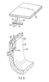
- the locking part 50 is attached as a downwardly projecting hook to the underside of the cover 10 in such a way that the inclined surface 51 of the locking part 50 has a smaller pitch angle than the inclined surface 31 of the locking part 30 and then when the cover 10 is on the support surface 61 of the component 20 is placed, the second inclined surface 51 is lower than the inclined surface 31.
- These two inclined surfaces 31 and 51 thus together again form an obliquely converging gap in which one end 41 of a locking piece 40 can be inserted.
- a pair of similar locking parts 30, 50 is provided on the other side (not shown) of the component 20, the insertion openings 32 and the inclined surfaces 31, 51 being of the same design, so that the locking piece 40 as a rod-shaped body, the component 20 in can be formed essentially transversely to its longitudinal axis.
- This embodiment of the invention differs from the previously shown embodiments in particular in that, after the cover 10 has been removed, there are no parts protruding beyond the inner wall 21 of the component 20, so cleaning of the interior of the component is facilitated.
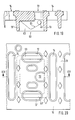
- FIGS. 12-23 A particularly preferred embodiment of the invention based on the principle arrangement just explained is explained in more detail below with reference to FIGS. 12-23.
- the embodiment shows a drainage channel (or components thereof) for heavy loads.
- the cover 10 does not lie directly on the upper edge 25 of the side wall 23 of the component 20, but the upper edge is formed by a reinforcing frame 60 which is shown in FIG the side wall (or its upper edge) is cast in.
- the reinforcing frame 60 is a metal (iron) cast part, which is shown schematically in the figures and (on each side of the drainage channel) has a support surface 61, a side edge 63 protruding vertically upwards from this and protruding angle webs 64 downwards, as is the case here is explained in more detail in the above-mentioned EP 0 081 762 A1.
- the locking part 30 again comprises an inclined surface 31 and an insertion opening 32, as was shown in principle with reference to FIG. 11 (in perspective).
- the locking part 30 is embedded in the “side wall” (or in the edge frame) of the drainage channel.
- a web 53 is attached, the upper edge of which forms the inclined surface 51 already described.
- the dimensioning is again such that a downwardly tapering gap is formed between the inclined surfaces 31 and 51, in which a locking piece 40 can be inserted.
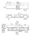
- This web 53 as can be seen more clearly from FIGS. 17-20, is cast along projecting perpendicularly from cross webs 13 of a cast grate. It can be connected to the crossbar 13 or to crossbars 13, 13 'either with only one end (see FIGS. 17, 18) or with both ends (see FIGS. 19 and 20). What is important here is the fact that the upper inclined surface 51 is formed in such a way that the correct position of the inclined surfaces 31 and 51 relative to one another is ensured when the cover 10 is placed on the component 20.
- a separate fixing part 70 (FIGS. 22, 23) is provided in the embodiment of the invention shown here, which can be inserted into a (central) opening 72 in the cover 10.
- the fixing part has a latching recess 71, into which a locking piece 40 can be inserted. This state is shown in Fig. 23.
- These fixing parts 70 could be removed as such. However, they preferably remain in the cover inserted.
- the locking piece 40 is then pushed upwards by means of an elongated instrument (screwdriver), the second inclined surface 51, so that it then comes into engagement with the fixing part 70. With further pushing, the fixing part 70 is pushed upward and reaches a position as shown in FIG. 23.
- the fixing part 70 remains in this position and holds the locking piece 40 due to frictional forces between the fixing part 70 and the cover 10. In this state, the cover 10 can be lifted off. If you now want to achieve a lock again, i.e. let the locking piece 40 slide the inclined surface 51 downwards, you simply press (step) on the fixing part 70, which then slides down and allows the locking piece 40 to slide out of the locking recess 71.
- a fixing part 70 is provided, which is essentially hook-shaped (see FIG. 27).
- This hook-shaped fixing part 70 has a bore 74 which is essentially adapted to the diameter of the locking piece 40.
- the fixing part 70 can thus be pushed onto the locking piece 40 up to approximately in the middle thereof.
- express reference is made to FIG. 26.
- the locking piece 40 In order to hold the locking piece 40 in its raised position, in which the cover 10 can be removed, the locking piece 40 is pushed upwards by means of an elongated instrument (screwdriver), the second inclined surface 51 (to the right in FIGS. 25 and 26), namely together with the fixing part 70.
- the section of the fixing part 70 leading during this movement comes into abutment with the crosspiece 13, so that the fixing part 70 slips with its hook opening under the lower edge of the crosspiece 13 and is attached to it. This will u. a. achieved by a sufficient elasticity of the fixing part 70 or the locking piece 40.
- the locking piece 40 In this position, the locking piece 40 thus hangs or is held by the fixing part 70 so that the cover 10 can be removed. If you want to reach the locking position again, you simply press on the hook end 75 so that it comes free from the crosspiece 13. As a result, the locking piece 40 falls down and produces the desired clamping effect.
- the fixing part 70 preferably sits frictionally on the locking piece 40. Furthermore, the fixing part 70 in the area of the bore 74 has a sufficient diameter such that, at least in the raised state (FIG. 25), the fixing part 70 is prevented from moving sideways back and forth by its stop with the edges of the opening 72 in the tread surface. In the fixed state of the locking piece 40, uniform handling of the cover 10 together with the locking pieces 40 can thus easily be carried out, since these are properly fixed to the cover 10 by means of the fixing parts 70.
- FIGS. 28 to 30 A further embodiment of the invention is shown in FIGS. 28 to 30, in which the locking piece 40 or its ends 41 do not slide down the inclined surface 51 due to the weight and thereby clamp themselves into the narrowing gap, but rather by means of a lever. Arrangement can be lifted up. In this case, the gap tapers upwards.
- This lever arrangement comprises a cranked rod (FIG. 30) which is hooked into hook-shaped supports 76 at the positions shown in FIG. 30, the weight of the cranked section 42 or of the ends 41, 41 'and the associated lever arms are dimensioned such that the cranked end 42 becomes overweight and tilts downward when suspended in the supports 76, 76 '.
- the supports 76 are attached to the cover 10.
- the locking parts 30, 50 are also again formed to the plane of symmetry S of the channel-shaped or channel-shaped component 20 and its cover 10.
- the fact that the webs 53 or lines of inclination of the inclined surfaces 51 parallel to the inner walls 21 of the building partly 20 run another advantage guaranteed, which comes into play when a horizontal force acting in the longitudinal direction of the component acts on the cover 10.
- the cover is displaced relative to the component 20, at least one pair of gaps between the locking parts 30 and 50 narrows, which is prevented by the clamping pieces 40.
- its great advantage of self-tensioning acts not only in the vertical direction (lifting off the cover 10) but also in the horizontal direction (moving the cover 10 on the component 20).
Landscapes
- Engineering & Computer Science (AREA)
- Architecture (AREA)
- Civil Engineering (AREA)
- Structural Engineering (AREA)
- Health & Medical Sciences (AREA)
- Life Sciences & Earth Sciences (AREA)
- Hydrology & Water Resources (AREA)
- Public Health (AREA)
- Water Supply & Treatment (AREA)
- Sewage (AREA)
- Water Treatment By Sorption (AREA)
- Devices For Blowing Cold Air, Devices For Blowing Warm Air, And Means For Preventing Water Condensation In Air Conditioning Units (AREA)
- Switch Cases, Indication, And Locking (AREA)
Priority Applications (1)
| Application Number | Priority Date | Filing Date | Title |
|---|---|---|---|
| DE9116688U DE9116688U1 (de) | 1990-09-20 | 1991-09-19 | Verriegelungsvorrichtung zum verriegelbaren Halten einer überfahrbaren Abdeckung auf einer Entwässerungsrinne |
Applications Claiming Priority (6)
| Application Number | Priority Date | Filing Date | Title |
|---|---|---|---|
| DE4029745A DE4029745A1 (de) | 1990-09-20 | 1990-09-20 | Entwaesserungsrinne |
| DE4029745 | 1990-09-20 | ||
| DE4108999 | 1991-03-19 | ||
| DE19914108999 DE4108999C1 (fr) | 1991-03-19 | 1991-03-19 | |
| DE4119118 | 1991-06-10 | ||
| DE4119118 | 1991-06-10 |
Publications (2)
| Publication Number | Publication Date |
|---|---|
| EP0476672A1 true EP0476672A1 (fr) | 1992-03-25 |
| EP0476672B1 EP0476672B1 (fr) | 1995-01-04 |
Family
ID=27201699
Family Applications (1)
| Application Number | Title | Priority Date | Filing Date |
|---|---|---|---|
| EP91115976A Expired - Lifetime EP0476672B1 (fr) | 1990-09-20 | 1991-09-19 | Dispositif pour retenir verrouillé un revêtement routier sur un caniveau d'écoulement |
Country Status (3)
| Country | Link |
|---|---|
| EP (1) | EP0476672B1 (fr) |
| AT (1) | ATE116702T1 (fr) |
| DE (1) | DE59104136D1 (fr) |
Cited By (9)
| Publication number | Priority date | Publication date | Assignee | Title |
|---|---|---|---|---|
| DE4241703A1 (de) * | 1992-12-10 | 1994-06-16 | Ahlmann Aco Severin | Oberflächenentwässerungseinrichtung |
| AU660563B2 (en) * | 1993-10-04 | 1995-06-29 | Michael Graham Richards | Improvements to grates |
| US5437516A (en) * | 1992-12-10 | 1995-08-01 | Aco Severin Ahlmann Gmbh & Co., Kg | Surface drainage apparatus |
| DE4403159A1 (de) * | 1994-02-02 | 1995-08-03 | Ahlmann Aco Severin | Entwässerungsrinne |
| EP0821112A1 (fr) * | 1996-07-24 | 1998-01-28 | MEA MEISINGER Stahl und Kunststoff GmbH | Couverture routière |
| WO2002090675A1 (fr) * | 2001-05-04 | 2002-11-14 | Aco Severin Ahlmann Gmbh & Co. Kg | Couvercle pour un systeme d'ecoulement des eaux |
| EP1457618A1 (fr) * | 2003-02-25 | 2004-09-15 | Franz Steggemann | Grille |
| EP1559839A1 (fr) * | 2004-01-27 | 2005-08-03 | Poly-Bauelemente AG | Caniveau d'écoulement |
| KR101060993B1 (ko) | 2011-03-29 | 2011-08-31 | 주식회사 우빈기술개발 | 우수 범람 방지를 위한 승하강식 배수로 |
Citations (4)
| Publication number | Priority date | Publication date | Assignee | Title |
|---|---|---|---|---|
| DE3133658A1 (de) * | 1980-08-28 | 1982-06-24 | Aktiebolaget Gustavsberg, Vörmdö | Einrichtung zum sichern von schachtabdeckungen |
| EP0081762A1 (fr) * | 1981-12-15 | 1983-06-22 | ACO Severin Ahlmann GmbH & Co. KG | Bord pour caniveaux d'écoulement |
| EP0204278A2 (fr) * | 1985-06-07 | 1986-12-10 | AG Hunziker & Cie. | Grille de recouvrement pour un caniveau d'écoulement |
| US4739896A (en) * | 1987-04-20 | 1988-04-26 | Moss Kathyleen D | Aircraft servicing pit with gravity operated lid latch |
-
1991
- 1991-09-19 DE DE59104136T patent/DE59104136D1/de not_active Expired - Fee Related
- 1991-09-19 AT AT91115976T patent/ATE116702T1/de not_active IP Right Cessation
- 1991-09-19 EP EP91115976A patent/EP0476672B1/fr not_active Expired - Lifetime
Patent Citations (4)
| Publication number | Priority date | Publication date | Assignee | Title |
|---|---|---|---|---|
| DE3133658A1 (de) * | 1980-08-28 | 1982-06-24 | Aktiebolaget Gustavsberg, Vörmdö | Einrichtung zum sichern von schachtabdeckungen |
| EP0081762A1 (fr) * | 1981-12-15 | 1983-06-22 | ACO Severin Ahlmann GmbH & Co. KG | Bord pour caniveaux d'écoulement |
| EP0204278A2 (fr) * | 1985-06-07 | 1986-12-10 | AG Hunziker & Cie. | Grille de recouvrement pour un caniveau d'écoulement |
| US4739896A (en) * | 1987-04-20 | 1988-04-26 | Moss Kathyleen D | Aircraft servicing pit with gravity operated lid latch |
Cited By (11)
| Publication number | Priority date | Publication date | Assignee | Title |
|---|---|---|---|---|
| DE4241703A1 (de) * | 1992-12-10 | 1994-06-16 | Ahlmann Aco Severin | Oberflächenentwässerungseinrichtung |
| US5437516A (en) * | 1992-12-10 | 1995-08-01 | Aco Severin Ahlmann Gmbh & Co., Kg | Surface drainage apparatus |
| US5466091A (en) * | 1992-12-10 | 1995-11-14 | Aco Severin Ahlmann Gmbh & Co., Kg | Surface drainage apparatus |
| AU660563B2 (en) * | 1993-10-04 | 1995-06-29 | Michael Graham Richards | Improvements to grates |
| DE4403159A1 (de) * | 1994-02-02 | 1995-08-03 | Ahlmann Aco Severin | Entwässerungsrinne |
| EP0821112A1 (fr) * | 1996-07-24 | 1998-01-28 | MEA MEISINGER Stahl und Kunststoff GmbH | Couverture routière |
| WO2002090675A1 (fr) * | 2001-05-04 | 2002-11-14 | Aco Severin Ahlmann Gmbh & Co. Kg | Couvercle pour un systeme d'ecoulement des eaux |
| US6945733B2 (en) | 2001-05-04 | 2005-09-20 | Aco Severin Ahlmann Gmbh & Co. Kg | Cover for a drainage device |
| EP1457618A1 (fr) * | 2003-02-25 | 2004-09-15 | Franz Steggemann | Grille |
| EP1559839A1 (fr) * | 2004-01-27 | 2005-08-03 | Poly-Bauelemente AG | Caniveau d'écoulement |
| KR101060993B1 (ko) | 2011-03-29 | 2011-08-31 | 주식회사 우빈기술개발 | 우수 범람 방지를 위한 승하강식 배수로 |
Also Published As
| Publication number | Publication date |
|---|---|
| DE59104136D1 (de) | 1995-02-16 |
| EP0476672B1 (fr) | 1995-01-04 |
| ATE116702T1 (de) | 1995-01-15 |
Similar Documents
| Publication | Publication Date | Title |
|---|---|---|
| DE3888364T3 (de) | Eine lasttragende vorrichtung. | |
| EP0514712B1 (fr) | Coffrage pour surfaces à courbure variable | |
| DE2554581C2 (de) | Anordnung scheibenförmiger, abnehmbarer Ballastgewichte | |
| DE69811156T2 (de) | Lastenträger für Kraftfahrzeuge mit fester Dachreling | |
| EP0596232B1 (fr) | Dispositif de support pour un élément de coffrage disposé à angle droit par rapport à l'axe longitudinal d'une poutre du coffrage | |
| DE60022490T2 (de) | Gerüstelemente mit verschlusselement | |
| EP0476672B1 (fr) | Dispositif pour retenir verrouillé un revêtement routier sur un caniveau d'écoulement | |
| DE4007950C2 (de) | Vorrichtung zum Verbinden und Verspannen von Schaltafeln | |
| DE4241707A1 (de) | Sicherungseinrichtung für eine Entwässerungsrinne | |
| DE2758992A1 (de) | Tragwerk zum heben und transportieren von insbesondere betonplatten durch ein hub- bzw. transportgeraet | |
| DE8914503U1 (de) | Geländer | |
| EP2224074A1 (fr) | Echafaudage avec un dispositif anti-levage pour plancher | |
| DE4108999C1 (fr) | ||
| DE19525316A1 (de) | Einrichtung zur Fixierung des schwingenden Systems einer Haushaltsmaschine | |
| EP1597441B1 (fr) | Dispositif de drainage | |
| DE10337263B3 (de) | Abdeckungsanordnung | |
| DE102009013197B4 (de) | Anschlagelement und Kombination aus einem Anschlagelement und einem Befestigungsmittel | |
| DE9116726U1 (de) | Verriegelungsvorrichtung zum verriegelbaren Halten einer übrfahrbaren Abdeckung auf einer Entwässerungsrinne | |
| EP0167991A2 (fr) | Dispositif de tête à pivot pour l'assemblage articulé et en tout temps démontable d'un étrésillon de tranchée à une paroi de blindage | |
| DE19637470A1 (de) | Verankerungsgerät | |
| DE9116696U1 (de) | Vorrichtung zum verriegelbaren Halten einer überfahrbaren Abdeckung auf einer Entwässerungsrinne | |
| DE60219099T2 (de) | Ablaufrinne und Rostanordnung | |
| DE9116688U1 (de) | Verriegelungsvorrichtung zum verriegelbaren Halten einer überfahrbaren Abdeckung auf einer Entwässerungsrinne | |
| DE102011053263A1 (de) | Leitschwellenschranke sowie Fahrzeugrückhaltesystem mit einer Leitschwellenschranke | |
| DE4403159C2 (de) | Entwässerungsrinne |
Legal Events
| Date | Code | Title | Description |
|---|---|---|---|
| PUAI | Public reference made under article 153(3) epc to a published international application that has entered the european phase |
Free format text: ORIGINAL CODE: 0009012 |
|
| AK | Designated contracting states |
Kind code of ref document: A1 Designated state(s): AT BE CH DE DK ES FR GB GR IT LI LU NL SE |
|
| 17P | Request for examination filed |
Effective date: 19920427 |
|
| 17Q | First examination report despatched |
Effective date: 19930517 |
|
| GRAA | (expected) grant |
Free format text: ORIGINAL CODE: 0009210 |
|
| AK | Designated contracting states |
Kind code of ref document: B1 Designated state(s): AT BE CH DE DK ES FR GB GR IT LI LU NL SE |
|
| PG25 | Lapsed in a contracting state [announced via postgrant information from national office to epo] |
Ref country code: IT Free format text: LAPSE BECAUSE OF FAILURE TO SUBMIT A TRANSLATION OF THE DESCRIPTION OR TO PAY THE FEE WITHIN THE PRE;WARNING: LAPSES OF ITALIAN PATENTS WITH EFFECTIVE DATE BEFORE 2007 MAY HAVE OCCURRED AT ANY TIME BEFORE 2007. THE CORRECT EFFECTIVE DATE MAY BE DIFFERENT FROM THE ONE RECORDED.SCRIBED TIME-LIMIT Effective date: 19950104 Ref country code: GR Free format text: LAPSE BECAUSE OF FAILURE TO SUBMIT A TRANSLATION OF THE DESCRIPTION OR TO PAY THE FEE WITHIN THE PRESCRIBED TIME-LIMIT Effective date: 19950104 Ref country code: BE Effective date: 19950104 Ref country code: DK Effective date: 19950104 Ref country code: ES Free format text: THE PATENT HAS BEEN ANNULLED BY A DECISION OF A NATIONAL AUTHORITY Effective date: 19950104 |
|
| REF | Corresponds to: |
Ref document number: 116702 Country of ref document: AT Date of ref document: 19950115 Kind code of ref document: T |
|
| ET | Fr: translation filed | ||
| REF | Corresponds to: |
Ref document number: 59104136 Country of ref document: DE Date of ref document: 19950216 |
|
| GBT | Gb: translation of ep patent filed (gb section 77(6)(a)/1977) |
Effective date: 19950120 |
|
| PG25 | Lapsed in a contracting state [announced via postgrant information from national office to epo] |
Ref country code: SE Effective date: 19950404 |
|
| PG25 | Lapsed in a contracting state [announced via postgrant information from national office to epo] |
Ref country code: AT Effective date: 19950919 |
|
| PG25 | Lapsed in a contracting state [announced via postgrant information from national office to epo] |
Ref country code: LU Free format text: LAPSE BECAUSE OF NON-PAYMENT OF DUE FEES Effective date: 19950930 |
|
| PLBE | No opposition filed within time limit |
Free format text: ORIGINAL CODE: 0009261 |
|
| STAA | Information on the status of an ep patent application or granted ep patent |
Free format text: STATUS: NO OPPOSITION FILED WITHIN TIME LIMIT |
|
| 26N | No opposition filed | ||
| PGFP | Annual fee paid to national office [announced via postgrant information from national office to epo] |
Ref country code: GB Payment date: 19960830 Year of fee payment: 6 |
|
| PGFP | Annual fee paid to national office [announced via postgrant information from national office to epo] |
Ref country code: CH Payment date: 19961202 Year of fee payment: 6 |
|
| PG25 | Lapsed in a contracting state [announced via postgrant information from national office to epo] |
Ref country code: GB Free format text: LAPSE BECAUSE OF NON-PAYMENT OF DUE FEES Effective date: 19970919 |
|
| PG25 | Lapsed in a contracting state [announced via postgrant information from national office to epo] |
Ref country code: CH Free format text: LAPSE BECAUSE OF NON-PAYMENT OF DUE FEES Effective date: 19970930 Ref country code: LI Free format text: LAPSE BECAUSE OF NON-PAYMENT OF DUE FEES Effective date: 19970930 |
|
| GBPC | Gb: european patent ceased through non-payment of renewal fee |
Effective date: 19970919 |
|
| REG | Reference to a national code |
Ref country code: CH Ref legal event code: PL |
|
| PGFP | Annual fee paid to national office [announced via postgrant information from national office to epo] |
Ref country code: NL Payment date: 19980930 Year of fee payment: 8 |
|
| PG25 | Lapsed in a contracting state [announced via postgrant information from national office to epo] |
Ref country code: NL Free format text: LAPSE BECAUSE OF NON-PAYMENT OF DUE FEES Effective date: 20000401 |
|
| NLV4 | Nl: lapsed or anulled due to non-payment of the annual fee |
Effective date: 20000401 |
|
| PGFP | Annual fee paid to national office [announced via postgrant information from national office to epo] |
Ref country code: FR Payment date: 20040917 Year of fee payment: 14 |
|
| PGFP | Annual fee paid to national office [announced via postgrant information from national office to epo] |
Ref country code: DE Payment date: 20051128 Year of fee payment: 15 |
|
| PG25 | Lapsed in a contracting state [announced via postgrant information from national office to epo] |
Ref country code: FR Free format text: LAPSE BECAUSE OF NON-PAYMENT OF DUE FEES Effective date: 20060531 |
|
| REG | Reference to a national code |
Ref country code: FR Ref legal event code: ST Effective date: 20060531 |
|
| PG25 | Lapsed in a contracting state [announced via postgrant information from national office to epo] |
Ref country code: DE Free format text: LAPSE BECAUSE OF NON-PAYMENT OF DUE FEES Effective date: 20070403 |