EP0474542B1 - Gerät und Verfahren zum Erkennen von Teppichböden und Treppen für einen Reinigungsroboter - Google Patents
Gerät und Verfahren zum Erkennen von Teppichböden und Treppen für einen Reinigungsroboter Download PDFInfo
- Publication number
- EP0474542B1 EP0474542B1 EP91402327A EP91402327A EP0474542B1 EP 0474542 B1 EP0474542 B1 EP 0474542B1 EP 91402327 A EP91402327 A EP 91402327A EP 91402327 A EP91402327 A EP 91402327A EP 0474542 B1 EP0474542 B1 EP 0474542B1
- Authority
- EP
- European Patent Office
- Prior art keywords
- ultrasonic wave
- wave signal
- signal
- floor
- frequency
- Prior art date
- Legal status (The legal status is an assumption and is not a legal conclusion. Google has not performed a legal analysis and makes no representation as to the accuracy of the status listed.)
- Expired - Lifetime
Links
- 238000004140 cleaning Methods 0.000 title claims description 17
- 238000000034 method Methods 0.000 title claims description 9
- 230000002123 temporal effect Effects 0.000 claims 1
- 230000005540 biological transmission Effects 0.000 description 8
- 238000010586 diagram Methods 0.000 description 4
- 230000007257 malfunction Effects 0.000 description 2
- 238000010276 construction Methods 0.000 description 1
- 230000010355 oscillation Effects 0.000 description 1
Images




Classifications
-
- A—HUMAN NECESSITIES
- A47—FURNITURE; DOMESTIC ARTICLES OR APPLIANCES; COFFEE MILLS; SPICE MILLS; SUCTION CLEANERS IN GENERAL
- A47L—DOMESTIC WASHING OR CLEANING; SUCTION CLEANERS IN GENERAL
- A47L11/00—Machines for cleaning floors, carpets, furniture, walls, or wall coverings
- A47L11/40—Parts or details of machines not provided for in groups A47L11/02 - A47L11/38, or not restricted to one of these groups, e.g. handles, arrangements of switches, skirts, buffers, levers
- A47L11/4011—Regulation of the cleaning machine by electric means; Control systems and remote control systems therefor
-
- A—HUMAN NECESSITIES
- A47—FURNITURE; DOMESTIC ARTICLES OR APPLIANCES; COFFEE MILLS; SPICE MILLS; SUCTION CLEANERS IN GENERAL
- A47L—DOMESTIC WASHING OR CLEANING; SUCTION CLEANERS IN GENERAL
- A47L11/00—Machines for cleaning floors, carpets, furniture, walls, or wall coverings
- A47L11/40—Parts or details of machines not provided for in groups A47L11/02 - A47L11/38, or not restricted to one of these groups, e.g. handles, arrangements of switches, skirts, buffers, levers
- A47L11/4061—Steering means; Means for avoiding obstacles; Details related to the place where the driver is accommodated
-
- G—PHYSICS
- G01—MEASURING; TESTING
- G01N—INVESTIGATING OR ANALYSING MATERIALS BY DETERMINING THEIR CHEMICAL OR PHYSICAL PROPERTIES
- G01N29/00—Investigating or analysing materials by the use of ultrasonic, sonic or infrasonic waves; Visualisation of the interior of objects by transmitting ultrasonic or sonic waves through the object
- G01N29/04—Analysing solids
- G01N29/07—Analysing solids by measuring propagation velocity or propagation time of acoustic waves
-
- G—PHYSICS
- G01—MEASURING; TESTING
- G01N—INVESTIGATING OR ANALYSING MATERIALS BY DETERMINING THEIR CHEMICAL OR PHYSICAL PROPERTIES
- G01N29/00—Investigating or analysing materials by the use of ultrasonic, sonic or infrasonic waves; Visualisation of the interior of objects by transmitting ultrasonic or sonic waves through the object
- G01N29/04—Analysing solids
- G01N29/11—Analysing solids by measuring attenuation of acoustic waves
-
- G—PHYSICS
- G01—MEASURING; TESTING
- G01S—RADIO DIRECTION-FINDING; RADIO NAVIGATION; DETERMINING DISTANCE OR VELOCITY BY USE OF RADIO WAVES; LOCATING OR PRESENCE-DETECTING BY USE OF THE REFLECTION OR RERADIATION OF RADIO WAVES; ANALOGOUS ARRANGEMENTS USING OTHER WAVES
- G01S7/00—Details of systems according to groups G01S13/00, G01S15/00, G01S17/00
- G01S7/52—Details of systems according to groups G01S13/00, G01S15/00, G01S17/00 of systems according to group G01S15/00
- G01S7/539—Details of systems according to groups G01S13/00, G01S15/00, G01S17/00 of systems according to group G01S15/00 using analysis of echo signal for target characterisation; Target signature; Target cross-section
-
- G—PHYSICS
- G05—CONTROLLING; REGULATING
- G05D—SYSTEMS FOR CONTROLLING OR REGULATING NON-ELECTRIC VARIABLES
- G05D1/00—Control of position, course, altitude or attitude of land, water, air or space vehicles, e.g. using automatic pilots
- G05D1/02—Control of position or course in two dimensions
- G05D1/021—Control of position or course in two dimensions specially adapted to land vehicles
- G05D1/0212—Control of position or course in two dimensions specially adapted to land vehicles with means for defining a desired trajectory
- G05D1/0214—Control of position or course in two dimensions specially adapted to land vehicles with means for defining a desired trajectory in accordance with safety or protection criteria, e.g. avoiding hazardous areas
-
- G—PHYSICS
- G05—CONTROLLING; REGULATING
- G05D—SYSTEMS FOR CONTROLLING OR REGULATING NON-ELECTRIC VARIABLES
- G05D1/00—Control of position, course, altitude or attitude of land, water, air or space vehicles, e.g. using automatic pilots
- G05D1/02—Control of position or course in two dimensions
- G05D1/021—Control of position or course in two dimensions specially adapted to land vehicles
- G05D1/0255—Control of position or course in two dimensions specially adapted to land vehicles using acoustic signals, e.g. ultra-sonic singals
-
- A—HUMAN NECESSITIES
- A47—FURNITURE; DOMESTIC ARTICLES OR APPLIANCES; COFFEE MILLS; SPICE MILLS; SUCTION CLEANERS IN GENERAL
- A47L—DOMESTIC WASHING OR CLEANING; SUCTION CLEANERS IN GENERAL
- A47L2201/00—Robotic cleaning machines, i.e. with automatic control of the travelling movement or the cleaning operation
- A47L2201/04—Automatic control of the travelling movement; Automatic obstacle detection
-
- G—PHYSICS
- G01—MEASURING; TESTING
- G01N—INVESTIGATING OR ANALYSING MATERIALS BY DETERMINING THEIR CHEMICAL OR PHYSICAL PROPERTIES
- G01N2291/00—Indexing codes associated with group G01N29/00
- G01N2291/02—Indexing codes associated with the analysed material
- G01N2291/028—Material parameters
- G01N2291/02854—Length, thickness
-
- G—PHYSICS
- G01—MEASURING; TESTING
- G01N—INVESTIGATING OR ANALYSING MATERIALS BY DETERMINING THEIR CHEMICAL OR PHYSICAL PROPERTIES
- G01N2291/00—Indexing codes associated with group G01N29/00
- G01N2291/04—Wave modes and trajectories
- G01N2291/044—Internal reflections (echoes), e.g. on walls or defects
-
- Y—GENERAL TAGGING OF NEW TECHNOLOGICAL DEVELOPMENTS; GENERAL TAGGING OF CROSS-SECTIONAL TECHNOLOGIES SPANNING OVER SEVERAL SECTIONS OF THE IPC; TECHNICAL SUBJECTS COVERED BY FORMER USPC CROSS-REFERENCE ART COLLECTIONS [XRACs] AND DIGESTS
- Y10—TECHNICAL SUBJECTS COVERED BY FORMER USPC
- Y10S—TECHNICAL SUBJECTS COVERED BY FORMER USPC CROSS-REFERENCE ART COLLECTIONS [XRACs] AND DIGESTS
- Y10S367/00—Communications, electrical: acoustic wave systems and devices
- Y10S367/903—Transmit-receive circuitry
Definitions
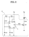
- the circuit comprises a receiving detector unit 71 which includes resistors R31 to R33, diodes D31 and D32, condensers C31 and C32 and a transistor Q31 and functions to detect the infrared ray received in the infrared ray receiver 5, that is a light receiving element, as a sine wave, a receiving amplifier unit 72 which includes resistors R34 to R40, condensers C33 to C37 and an operational amplifier OP31 and functions to compare the output signal from the infrared ray receiver 5 with an offset voltage and then amplify it, and a receiving demodulator unit 73 which includes inverters IN31 to IN33, a diode D33, a condenser C38 and a resistor R41 and functions to smooth the output signal from said receiving amplifier unit 72 to demodulate it and then apply it to the input terminal PAO of a microcomputer 8.
- a receiving detector unit 71 which includes resistors R31 to R33, diodes D31 and D32, condensers
- the oscillating element 7 of the infrared ray transmitting circuit 6 generates square wave of 1 KHz according to the time constant set by the resistors R22 and R23 and the condenser C21.
- the infrared signals outputted from the infrared ray transmitter 4 as above-mentioned are reflected against the floor and then received in the infrared ray receiver 5. Accordingly, the infrared ray receiver 5 also repeats to be turned on and off at the period of 1 msec so that sine waves are outputted, at the period of 1 msec, from the output terminal of the receiving detector 71 which is connected to the collector of the infrared ray receiver 5.
- the ultrasonic wave signal transmitting means 11 comprises an oscillating integrated element IC4 for generating the oscillating signal of 1 MHz, a ten frequency-dividing integrated element IC1 for frequency-dividing the oscillating signal from the oscillating integrated element IC4 by ten, a flip-flop IC2 for frequency-dividing an output signal from the ten frequency-dividing integrated element IC1 by two, a flip-flop IC3 for receiving a clear signal from the microcomputer 8 and frequency-dividing an output signal from the flip-flop IC2 by two, and an ultrasonic wave signal transmitter 9 for receiving the two frequency-divided signal from the flip-flop IC3 to transmit the ultrasonic wave signal to the receiving amplifying means 121.
- an oscillating integrated element IC4 for generating the oscillating signal of 1 MHz
- a ten frequency-dividing integrated element IC1 for frequency-dividing the oscillating signal from the oscillating integrated element IC4 by ten
- a flip-flop IC2 for frequency-dividing an
- the ultrasonic wave signal transmitter 9 and the ultrasonic wave signal receiver 10 are used in place of the infrared ray transmitter 4 and the infrared ray receiver 5 shown in FIG. 1. In this case, they are mounted to be vertically apart 10 cm from the floor to be cleaned.
- the ultrasonic wave signal of 25 KHz transmitted from the ultrasonic wave signal transmitter 9 is reflected from the floor and is then received to the ultrasonic wave signal receiver 10, which then outputs a sinusoidal wave signal of 25 KHz.
- the amplitude of the sinusoidal wave signal is proportional to the magnitude of the received ultrasonic wave signal.
- the sinusoidal wave signal outputted from the ultrasonic wave signal receiver 10 is amplified and the amplified signal is applied to the inverting terminal of the operational amplifier OP52, and the reference signal, which is the DC offset signal supplied by power source Vcc and resistors R55 and R54, is applied to the non-inverting terminal thereof to be compared with the amplified signal in the operational amplifier OP52.
- the ultrasonic wave signal receiver 10 receives the ultrasonic wave signal having the magnitude above a predetermined value, a high potential signal is applied to the input terminal PAO of the microcomputer 8 by means of the receiving amplifying means 121 and the receiving demodulating means 122.
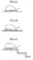
- the ultrasonic wave signal transmitted from the ultrasonic wave signal transmitter 9 is directly reflected against the floor which is vertically apart 10 cm from the bottom of the cleaning robot and then received in the ultrasonic wave signal receiver 10.
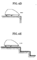
- the ultrasonic wave signal transmitted from the ultrasonic wave signal transmitter 9 is hardly received in the ultrasonic wave signal receiver 10 because the stair bottom surface is distantly apart from the bottom of the cleaning robot.
- the distance is calculated as 34 cm.
- the distance from the stair bottom surface is measured as the sum of 10 cm + the stair height ⁇ 2 cm.
- the ultrasonic wave signal is transmitted again for 1 msec. The distance is then measured again In the above-mentioned manner. Even though in the case that the cleaning robot travels on a carpet as shown In FIG. 4B. the ultrasonic wave signal is greatly absorbed in the carpet, it is received in the ultrasonic wave signal receiver. This is because the magnitude of the transmitted ultrasonic wave signal is high, in virtue of the transmission of ultrasonic wave signal for a relatively long period, that is 1 msec. As a result, the distance from the floor to be cleaned is measured as 10 cm ⁇ 2 cm.
- the distance from the stair bottom surface is measured as the sum of 10 cm + the stair height ⁇ 2 cm.
- the distance is measured as 34 cm, because the ultrasonic wave signal receiver 10 receives no ultrasonic wave signal.
- the present invention enables to determine correctly whether the floor to be cleaned is a normal floor, a floor covered with a carpet, or stairs. In accordance with the present invention, there is any possibility of occurring malfunction due to environment.
Landscapes
- Physics & Mathematics (AREA)
- Engineering & Computer Science (AREA)
- General Physics & Mathematics (AREA)
- Radar, Positioning & Navigation (AREA)
- Remote Sensing (AREA)
- Acoustics & Sound (AREA)
- Analytical Chemistry (AREA)
- Pathology (AREA)
- Life Sciences & Earth Sciences (AREA)
- Chemical & Material Sciences (AREA)
- Health & Medical Sciences (AREA)
- Biochemistry (AREA)
- General Health & Medical Sciences (AREA)
- Immunology (AREA)
- Automation & Control Theory (AREA)
- Aviation & Aerospace Engineering (AREA)
- Computer Networks & Wireless Communication (AREA)
- Electric Vacuum Cleaner (AREA)
- Control Of Position, Course, Altitude, Or Attitude Of Moving Bodies (AREA)
- Geophysics And Detection Of Objects (AREA)
- Length Measuring Devices Characterised By Use Of Acoustic Means (AREA)
- Investigating Or Analyzing Materials By The Use Of Ultrasonic Waves (AREA)
Claims (7)
- Ein Gerät für einen Reinigungsroboter zum Erkennen von Teppichböden und Treppen auf dem Boden, welches umfaßt : eine Sendereinrichtung (11) von Ultraschallwellensignalen, die dazu geeignet ist, ein frequenzgeteiltes, oszillierendes Signal an einen Ultraschallsender unter einer Steuerung eines Mikrocomputers (8) zu senden;eine Empfangsverstärkungseinrichtung (121), die dazu geeignet ist, ein Ultraschallwellensignal zu empfangen, das von der Sendeeinrichtung (11) von Ultraschallwellensignalen gesendet wird, und die Amplitude des empfangenen Ultraschallwellensignals mit einer Offset-Gleichspannung zu vergleichen-verstärken; undeine Empfangsdemodulationseinrichtung (122), die dafür geeignet ist, ein Ausgangssignal von der Empfangsverstärkungseinrichtung (121) zu demodulieren und das demodulierte Signal auf den Mikrocomputer (8) abzugeben, wobei der Mikrocomputer (8) eingerichtet ist, um das frequenzgeteilten, oszillierenden Signal an den Ultraschallwellensignalsender während einer ersten Zeitspanne zu liefern,zu testen, ob der Boden in einer der drei Zustände ist, die einen normalen Boden, einen teppichbedeckten Boden, oder Stufen beinhalten, als eine Funktion der ersten Zeitperiode und der Entfernung, die aus der zeitlichen Differenz zwischen der Zeit, wenn das Ultraschallwellensignal gesendet wird, und der Zeit, wenn es empfangen wird, mit dem vertikalen Abstand der vertikalen Position des Senders und der Empfangseinrichtung zu dem Boden verglichen wird, berechnet wird,den ersten von den drei Zuständen als eine Möglichkeit zu beseitigen, so daß dieser nicht wieder getestet wird, wenn er nicht der Zustand des Bodens ist, undum die Schritte, die in dem Mikrocomputer (8) durchgeführt werden, während einer zweiten Zeitspanne, die länger als die erste Zeitspanne ist, zu wiederholen, bis der Zustand des Bodens bestimmt ist.
- Ein Gerät nach Anspruch 1, worin die Sendereinrichtung (11) von Ultraschallwellensignalen beinhaltet :ein oszillierendes, integriertes Element (IC4) zum Erzeugen eines oszillierenden Signales mit einer vorbestimmten Frequenz;eine Frequenzteilereinrichtung (IC1, IC2, IC3) zur Frequenzteilung des oszillierenden Signales von dem oszillierenden, integrierten Element (IC4) durch einen vorbestimmten Wert, um eine vorbestimmte Frequenz des Signales zu erhalten; und ein Ultraschallwellensignalsender (9) zum Empfangen des frequenzgeteilten Ausgangssignales von der Frequenzteilereinrichtung (IC1, IC2, IC3), um das Ultraschallwellensignal an die Verstärkungseinrichtung (121) zu senden.
- Ein Gerät nach Anspruch 2, worin die Frequenzteilereinrichtung beinhaltet :ein integriertes Element (IC1) zum Frequenzteilen des oszillierenden Signales von dem oszillierenden, integrierten Element (IC4) durch zehn;ein erstes Flip-Flop (IC2) zum Frequenzteilen eines Ausgangssignales von dem integrierten Element (IC1) durch zwei; undein zweites Flip-Flop (IC3) zum Empfangen eines Freigabesignals von dem Mikrocomputer (8) und zum Frequenzteilen eines Ausgangssignales von dem ersten Flip-Flop (IC2) durch zwei und zum Anwenden des frequenzgeteilten Signales an den Ultraschallwellensignalsender (9).
- Ein Gerät nach Anspruch 1, 2 oder 3, worin die Empfangsverstärkungseinrichtung (121) so ausgestaltet ist, daß das Ausgangssignal eines Ultraschallwellenempfängers (10) durch einen Funktionsverstärker (OP51) verstärkt wird, bei welchem der nicht invertierte Eingangsanschluß an eine Gleichstrom-Offset-Spannungsquelle angeschlossen ist.
- Ein Gerät nach einer der Ansprüche 1 bis 4, worin die Empfangsdemodulationseinrichtung (122) eine Demodulationsschaltung aufweist, um das Ultraschallwellensignal zu demodulieren, das durch die Empfangsverstärkungseinrichtung (121) verstärkt wird, und um das demodulierte Signal an den Mikrocomputer (8) zu geben.
- Ein Gerät nach Anspruch 5, worin die Demodulationsschaltung beinhaltet:einen ersten Inverter (IN51), der mit einem Ausgangsanschluß der Empfangsverstärkungseinrichtung (121) verbunden ist;eine Diode (D51), die mit einem Ausgangsanschluß des ersten Inverters (IN51) verbunden ist;einen zweiten Inverter (IN52), der mit der Diode (D51) verbunden ist;einen dritten Inverter (IN53), dessen Eingangsanschluß mit einem Ausgangsanschluß des zweiten Inverters (IN52) verbunden ist und dessen Ausgangsanschluß mit dem Mikrocomputer (8) verbunden ist; undeinen Widerstand (R57) und einen Kondensator (C54), die parallel zwischen der Diode (D51) und dem zweiten Inverter (IN52) angeschlossen sind.
- Ein Verfahren zum Erkennen von Teppichböden und Treppen für einen Reinigungsroboter, das folgende Schritte umfaßt:Senden eines Ultraschallwellensignales während einer ersten vorbestimmten Zeitspanne (tl) durch einen Ultraschallwellensignalsender (9) unter der Steuerung eines Mikrocomputers (8);Messen der Zeitspanne von der Zeit, wenn das Ultraschallwellensignal gesendet wird zu der Zeit, wenn ein Ultraschallwellensignal-Anzeigesignal erzeugt wird, sobald das Ultraschallwellensignal in einem Ultraschallwellensignalempfänger (10) empfangen wird, und dann Berechnen einer Entfernung aus der gemessenen Zeitspanne;wenn die berechnete Entfernung nicht größer als die Summe der vertikalen Entfernung (d1) von der vertikalen Position des Ultraschallwellensignalsenders und des Empfängers (9, 10) zu dem Boden, der zu säubern ist und einer Toleranz (e) ist, Erkennen des Bodens, der zu säubern ist als ein normaler Boden; undwenn die berechnete Entfernung mehr als die Summe der vertikalen Entfernung (d1) und der Toleranz (e) ist, erneutes Senden des Ultraschallwellensignals während einer zweiten vorbestimmten Zeitperiode (t1 + a), welche länger als die erste vorbestimmte Zeitperiode (t1) ist, um eine neue Entfernung entsprechend dem Verfahren, das in dem Entfernungsberechnungsschritt durchgeführt wird, zu berechnen, und wenn die berechnete Entfernung nicht mehr als die Summe der vertikalen Entfernung (d1) und der Toleranz (e) ist, Erkennen des Bodens, der zu säubern ist, als ein Teppichboden bedeckter Boden, während, wenn die berechnete Entfernung mehr als die Summe der vertikalen Entfernung (d1) und der Toleranz (e) ist, Erkennen des Bodens, der zu säubern ist, als Stufen.
Applications Claiming Priority (3)
| Application Number | Priority Date | Filing Date | Title |
|---|---|---|---|
| KR1341390 | 1990-08-29 | ||
| KR1019900013413A KR920007588B1 (ko) | 1990-08-29 | 1990-08-29 | 자동주행청소기의 카페트 및 계단감지장치 및 방법 |
| US07/750,403 US5307273A (en) | 1990-08-29 | 1991-08-27 | Apparatus and method for recognizing carpets and stairs by cleaning robot |
Publications (3)
| Publication Number | Publication Date |
|---|---|
| EP0474542A2 EP0474542A2 (de) | 1992-03-11 |
| EP0474542A3 EP0474542A3 (en) | 1993-01-13 |
| EP0474542B1 true EP0474542B1 (de) | 1996-06-12 |
Family
ID=26628333
Family Applications (1)
| Application Number | Title | Priority Date | Filing Date |
|---|---|---|---|
| EP91402327A Expired - Lifetime EP0474542B1 (de) | 1990-08-29 | 1991-08-28 | Gerät und Verfahren zum Erkennen von Teppichböden und Treppen für einen Reinigungsroboter |
Country Status (3)
| Country | Link |
|---|---|
| US (1) | US5307273A (de) |
| EP (1) | EP0474542B1 (de) |
| JP (1) | JPH04233453A (de) |
Families Citing this family (80)
| Publication number | Priority date | Publication date | Assignee | Title |
|---|---|---|---|---|
| BE1008470A3 (fr) * | 1994-07-04 | 1996-05-07 | Colens Andre | Dispositif et systeme automatique de depoussierage de sol et engin y adapte. |
| US5510984A (en) * | 1994-11-28 | 1996-04-23 | Board Of Regents-Univ. Of Nebraska | Automated guided vehicle enunciator system |
| DE29818932U1 (de) * | 1998-10-23 | 2000-01-20 | Siemens AG, 80333 München | Absturzsicheres autonomes Fahrsystem mit Bereichsmarken |
| DE29818922U1 (de) * | 1998-10-23 | 2000-01-05 | Siemens AG, 80333 München | Absturzsicheres autonomes Fahrsystem mit Begrenzungsmarken |
| CA2374976C (en) * | 1999-06-08 | 2006-05-30 | S.C. Johnson Commercial Markets, Inc. | Floor cleaning apparatus |
| US6349936B1 (en) * | 2000-06-08 | 2002-02-26 | Heidelberger Druckmaschinen | Device for measuring the height of a sheet pile by using a reflectively operating radiation detector |
| US8788092B2 (en) * | 2000-01-24 | 2014-07-22 | Irobot Corporation | Obstacle following sensor scheme for a mobile robot |
| US8412377B2 (en) * | 2000-01-24 | 2013-04-02 | Irobot Corporation | Obstacle following sensor scheme for a mobile robot |
| US6956348B2 (en) | 2004-01-28 | 2005-10-18 | Irobot Corporation | Debris sensor for cleaning apparatus |
| US7571511B2 (en) | 2002-01-03 | 2009-08-11 | Irobot Corporation | Autonomous floor-cleaning robot |
| US6690134B1 (en) | 2001-01-24 | 2004-02-10 | Irobot Corporation | Method and system for robot localization and confinement |
| US7429843B2 (en) | 2001-06-12 | 2008-09-30 | Irobot Corporation | Method and system for multi-mode coverage for an autonomous robot |
| ATE510247T1 (de) * | 2001-06-12 | 2011-06-15 | Irobot Corp | Verfahren und system zur multimodalen bedeckung für einen autonomen roboter |
| US8396592B2 (en) | 2001-06-12 | 2013-03-12 | Irobot Corporation | Method and system for multi-mode coverage for an autonomous robot |
| US9128486B2 (en) * | 2002-01-24 | 2015-09-08 | Irobot Corporation | Navigational control system for a robotic device |
| DE10231386B4 (de) | 2002-07-08 | 2004-05-06 | Alfred Kärcher Gmbh & Co. Kg | Sensorvorrichtung sowie selbstfahrendes Bodenreinigungsgerät mit einer Sensorvorrichtung |
| US8428778B2 (en) | 2002-09-13 | 2013-04-23 | Irobot Corporation | Navigational control system for a robotic device |
| US8386081B2 (en) | 2002-09-13 | 2013-02-26 | Irobot Corporation | Navigational control system for a robotic device |
| US20050010331A1 (en) * | 2003-03-14 | 2005-01-13 | Taylor Charles E. | Robot vacuum with floor type modes |
| US7805220B2 (en) * | 2003-03-14 | 2010-09-28 | Sharper Image Acquisition Llc | Robot vacuum with internal mapping system |
| US20040211444A1 (en) * | 2003-03-14 | 2004-10-28 | Taylor Charles E. | Robot vacuum with particulate detector |
| US20040200505A1 (en) * | 2003-03-14 | 2004-10-14 | Taylor Charles E. | Robot vac with retractable power cord |
| US7801645B2 (en) * | 2003-03-14 | 2010-09-21 | Sharper Image Acquisition Llc | Robotic vacuum cleaner with edge and object detection system |
| US7332890B2 (en) | 2004-01-21 | 2008-02-19 | Irobot Corporation | Autonomous robot auto-docking and energy management systems and methods |
| US20060020369A1 (en) * | 2004-03-11 | 2006-01-26 | Taylor Charles E | Robot vacuum cleaner |
| DE112005000738T5 (de) | 2004-03-29 | 2007-04-26 | Evolution Robotics, Inc., Pasadena | Verfahren und Vorrichtung zur Positionsbestimmung unter Verwendung von reflektierten Lichtquellen |
| US7349091B2 (en) * | 2004-06-04 | 2008-03-25 | Sharp Kabushiki Kaisha | Optical object discriminating device |
| WO2006002385A1 (en) | 2004-06-24 | 2006-01-05 | Irobot Corporation | Programming and diagnostic tool for a mobile robot |
| US7706917B1 (en) * | 2004-07-07 | 2010-04-27 | Irobot Corporation | Celestial navigation system for an autonomous robot |
| US8972052B2 (en) * | 2004-07-07 | 2015-03-03 | Irobot Corporation | Celestial navigation system for an autonomous vehicle |
| KR101247933B1 (ko) | 2005-02-18 | 2013-03-26 | 아이로보트 코퍼레이션 | 습식 및 건식 청소를 위한 자동 표면 청소 로봇 |
| US7620476B2 (en) | 2005-02-18 | 2009-11-17 | Irobot Corporation | Autonomous surface cleaning robot for dry cleaning |
| US8392021B2 (en) | 2005-02-18 | 2013-03-05 | Irobot Corporation | Autonomous surface cleaning robot for wet cleaning |
| US8930023B2 (en) | 2009-11-06 | 2015-01-06 | Irobot Corporation | Localization by learning of wave-signal distributions |
| WO2007008148A1 (en) * | 2005-07-08 | 2007-01-18 | Ab Electrolux | Robotic cleaning device |
| ES2706729T3 (es) | 2005-12-02 | 2019-04-01 | Irobot Corp | Sistema de robot |
| EP2816434A3 (de) | 2005-12-02 | 2015-01-28 | iRobot Corporation | Roboter mit autonomem Wirkungsbereich |
| KR101099808B1 (ko) | 2005-12-02 | 2011-12-27 | 아이로보트 코퍼레이션 | 로봇 시스템 |
| EP2251757B1 (de) | 2005-12-02 | 2011-11-23 | iRobot Corporation | Abdeckungsrobotermobilität |
| WO2007065034A1 (en) | 2005-12-02 | 2007-06-07 | Irobot Corporation | Modular robot |
| ES2583374T3 (es) | 2006-05-19 | 2016-09-20 | Irobot Corporation | Eliminación de residuos de robots de limpieza |
| US8417383B2 (en) | 2006-05-31 | 2013-04-09 | Irobot Corporation | Detecting robot stasis |
| KR100815570B1 (ko) * | 2006-12-06 | 2008-03-20 | 삼성광주전자 주식회사 | 로봇청소기시스템 및 그 제어방법 |
| EP2574265B1 (de) | 2007-05-09 | 2015-10-14 | iRobot Corporation | Kompakter Roboter mit autonomer Reichweite |
| US8800107B2 (en) | 2010-02-16 | 2014-08-12 | Irobot Corporation | Vacuum brush |
| CN107422723B (zh) | 2010-12-30 | 2021-08-24 | 美国iRobot公司 | 覆盖机器人导航 |
| ES2610755T3 (es) | 2012-08-27 | 2017-05-03 | Aktiebolaget Electrolux | Sistema de posicionamiento de un robot |
| KR102015325B1 (ko) | 2013-01-29 | 2019-08-28 | 삼성전자주식회사 | 청소 로봇 및 그 제어 방법 |
| EP2986192B1 (de) | 2013-04-15 | 2021-03-31 | Aktiebolaget Electrolux | Robotischer staubsauger |
| CN105101855A (zh) | 2013-04-15 | 2015-11-25 | 伊莱克斯公司 | 具有伸出的侧刷的机器人真空吸尘器 |
| WO2015060672A1 (ko) * | 2013-10-25 | 2015-04-30 | 삼성전자주식회사 | 청소 로봇 |
| KR102153351B1 (ko) * | 2013-10-25 | 2020-09-21 | 삼성전자주식회사 | 청소 로봇 |
| KR102117269B1 (ko) * | 2013-10-25 | 2020-06-01 | 삼성전자주식회사 | 청소 로봇 |
| CN105849660B (zh) | 2013-12-19 | 2020-05-08 | 伊莱克斯公司 | 机器人清扫装置 |
| WO2015090402A1 (en) | 2013-12-19 | 2015-06-25 | Aktiebolaget Electrolux | Robotic cleaning device with perimeter recording function |
| EP3082537B1 (de) | 2013-12-19 | 2020-11-18 | Aktiebolaget Electrolux | Robotische reinigungsvorrichtung und verfahren zur bezugspunkterkennung |
| CN105792721B (zh) | 2013-12-19 | 2020-07-21 | 伊莱克斯公司 | 以螺旋样式移动的带侧刷的机器人真空吸尘器 |
| EP3084539B1 (de) | 2013-12-19 | 2019-02-20 | Aktiebolaget Electrolux | Priorisierung von reinigungsbereichen |
| KR102099495B1 (ko) | 2013-12-19 | 2020-04-09 | 에이비 엘렉트로룩스 | 로봇 청소 장치가 장애물에 올라가는 것의 감지 |
| JP6638987B2 (ja) | 2013-12-19 | 2020-02-05 | アクチエボラゲット エレクトロルックス | 回転側面ブラシの適応速度制御 |
| KR102116595B1 (ko) | 2013-12-20 | 2020-06-05 | 에이비 엘렉트로룩스 | 먼지통 |
| WO2016005012A1 (en) | 2014-07-10 | 2016-01-14 | Aktiebolaget Electrolux | Method for detecting a measurement error in a robotic cleaning device |
| JP6443897B2 (ja) | 2014-09-08 | 2018-12-26 | アクチエボラゲット エレクトロルックス | ロボット真空掃除機 |
| EP3190938A1 (de) | 2014-09-08 | 2017-07-19 | Aktiebolaget Electrolux | Robotischer staubsauger |
| EP3230814B1 (de) | 2014-12-10 | 2021-02-17 | Aktiebolaget Electrolux | Verwendung eines lasersensors zur bodentypdetektion |
| CN107072454A (zh) | 2014-12-12 | 2017-08-18 | 伊莱克斯公司 | 侧刷和机器人吸尘器 |
| KR102339531B1 (ko) | 2014-12-16 | 2021-12-16 | 에이비 엘렉트로룩스 | 로봇 청소 장치를 위한 경험-기반의 로드맵 |
| JP6532530B2 (ja) | 2014-12-16 | 2019-06-19 | アクチエボラゲット エレクトロルックス | ロボット掃除機の掃除方法 |
| US9868211B2 (en) | 2015-04-09 | 2018-01-16 | Irobot Corporation | Restricting movement of a mobile robot |
| US11099554B2 (en) | 2015-04-17 | 2021-08-24 | Aktiebolaget Electrolux | Robotic cleaning device and a method of controlling the robotic cleaning device |
| WO2017036532A1 (en) | 2015-09-03 | 2017-03-09 | Aktiebolaget Electrolux | System of robotic cleaning devices |
| CN108603935A (zh) | 2016-03-15 | 2018-09-28 | 伊莱克斯公司 | 机器人清洁设备以及机器人清洁设备进行陡壁检测的方法 |
| CN109068908B (zh) | 2016-05-11 | 2021-05-11 | 伊莱克斯公司 | 机器人清洁设备 |
| JP7243967B2 (ja) | 2017-06-02 | 2023-03-22 | アクチエボラゲット エレクトロルックス | ロボット清掃デバイスの前方の表面のレベル差を検出する方法 |
| JP6989210B2 (ja) | 2017-09-26 | 2022-01-05 | アクチエボラゲット エレクトロルックス | ロボット清掃デバイスの移動の制御 |
| CN110018239B (zh) * | 2019-04-04 | 2022-07-08 | 珠海一微半导体股份有限公司 | 一种地毯检测方法 |
| CN110514744B (zh) | 2019-08-20 | 2020-05-05 | 珠海市一微半导体有限公司 | 一种地面介质的判断阈值的修正方法及其检测方法 |
| CN116172445A (zh) | 2020-02-27 | 2023-05-30 | 北京石头创新科技有限公司 | 清洁机器人地毯识别方法 |
| CN113303733B (zh) | 2020-02-27 | 2022-10-18 | 北京石头创新科技有限公司 | 清洁机器人 |
| CN114310871B (zh) * | 2021-11-25 | 2024-07-09 | 云鲸智能(深圳)有限公司 | 机器人的控制方法、机器人、控制装置及可读存储介质 |
Family Cites Families (12)
| Publication number | Priority date | Publication date | Assignee | Title |
|---|---|---|---|---|
| CH656954A5 (de) * | 1981-10-30 | 1986-07-31 | Maag Zahnraeder & Maschinen Ag | Verfahren und anordnung zum auswerten von signalen aus einem ultraschallwegmesssystem. |
| US4542489A (en) * | 1982-05-18 | 1985-09-17 | Aisin Seiki Kabushiki Kaisha | Object detecting system of reflection type |
| US4674057A (en) * | 1984-02-14 | 1987-06-16 | Lockheed Corporation | Ultrasonic ranging control system for industrial robots |
| JPS6167240U (de) * | 1984-10-09 | 1986-05-08 | ||
| JPS61167889A (ja) * | 1985-01-18 | 1986-07-29 | Nippon Soken Inc | 距離測定装置 |
| US4685093A (en) * | 1985-04-03 | 1987-08-04 | Brookes & Gatehouse Limited | Speed measurement device |
| JPS639415A (ja) * | 1986-06-30 | 1988-01-16 | 松下電器産業株式会社 | 掃除機用床ノズル |
| JP2820407B2 (ja) * | 1988-02-16 | 1998-11-05 | 松下電器産業株式会社 | 自走式掃除機 |
| JP2568618B2 (ja) * | 1988-03-11 | 1997-01-08 | 松下電器産業株式会社 | 床面判別器 |
| US5076384A (en) * | 1989-10-17 | 1991-12-31 | Mitsubishi Denki Kabushiki Kaisha | Ultrasonic obstacle sensor |
| US5109566A (en) * | 1990-06-28 | 1992-05-05 | Matsushita Electric Industrial Co., Ltd. | Self-running cleaning apparatus |
| US5086535A (en) * | 1990-10-22 | 1992-02-11 | Racine Industries, Inc. | Machine and method using graphic data for treating a surface |
-
1991
- 1991-08-27 US US07/750,403 patent/US5307273A/en not_active Expired - Fee Related
- 1991-08-28 EP EP91402327A patent/EP0474542B1/de not_active Expired - Lifetime
- 1991-08-29 JP JP3218688A patent/JPH04233453A/ja active Pending
Also Published As
| Publication number | Publication date |
|---|---|
| US5307273A (en) | 1994-04-26 |
| EP0474542A3 (en) | 1993-01-13 |
| EP0474542A2 (de) | 1992-03-11 |
| JPH04233453A (ja) | 1992-08-21 |
Similar Documents
| Publication | Publication Date | Title |
|---|---|---|
| EP0474542B1 (de) | Gerät und Verfahren zum Erkennen von Teppichböden und Treppen für einen Reinigungsroboter | |
| US5498914A (en) | Capacitive sensor circuit | |
| CA2300332A1 (en) | Position sensing based on ultrasound emission | |
| US4677595A (en) | Ultrasonic vehicle rangefinder | |
| US4597068A (en) | Acoustic ranging system | |
| KR920007588B1 (ko) | 자동주행청소기의 카페트 및 계단감지장치 및 방법 | |
| JP2820407B2 (ja) | 自走式掃除機 | |
| KR890004974Y1 (ko) | 텔레비젼 수상기용 초음파를 이용한 자동거리 감지장치 | |
| KR0175512B1 (ko) | 진공청소기 | |
| JPH05150045A (ja) | レーザレーダ装置 | |
| JPH0146037B2 (de) | ||
| JPS5828222Y2 (ja) | エレベ−タホ−ルの物体検出装置 | |
| JPH0432994B2 (de) | ||
| JPH0419513B2 (de) | ||
| RU2049455C1 (ru) | Устройство для ориентации слепых | |
| JP3002667U (ja) | 盲人用道案内装置 | |
| JPS6331191Y2 (de) | ||
| KR20000056486A (ko) | 물체감지장치 및 그 방법 | |
| JPH0515112Y2 (de) | ||
| JPS61170684A (ja) | 車両用測距装置 | |
| JPS6180471U (de) | ||
| JP2584794Y2 (ja) | 超音波検出装置 | |
| JPS6123983A (ja) | 超音波送受信装置 | |
| JPS57191579A (en) | Ultrasonic transmitter and receiver | |
| JPS6112127A (ja) | 無線受信機 |
Legal Events
| Date | Code | Title | Description |
|---|---|---|---|
| PUAI | Public reference made under article 153(3) epc to a published international application that has entered the european phase |
Free format text: ORIGINAL CODE: 0009012 |
|
| 17P | Request for examination filed |
Effective date: 19910902 |
|
| AK | Designated contracting states |
Kind code of ref document: A2 Designated state(s): DE FR GB SE |
|
| PUAL | Search report despatched |
Free format text: ORIGINAL CODE: 0009013 |
|
| AK | Designated contracting states |
Kind code of ref document: A3 Designated state(s): DE FR GB SE |
|
| 17Q | First examination report despatched |
Effective date: 19950103 |
|
| RAP1 | Party data changed (applicant data changed or rights of an application transferred) |
Owner name: LG ELECTRONICS INC. |
|
| GRAH | Despatch of communication of intention to grant a patent |
Free format text: ORIGINAL CODE: EPIDOS IGRA |
|
| GRAH | Despatch of communication of intention to grant a patent |
Free format text: ORIGINAL CODE: EPIDOS IGRA |
|
| GRAA | (expected) grant |
Free format text: ORIGINAL CODE: 0009210 |
|
| AK | Designated contracting states |
Kind code of ref document: B1 Designated state(s): DE FR GB SE |
|
| REF | Corresponds to: |
Ref document number: 69120176 Country of ref document: DE Date of ref document: 19960718 |
|
| ET | Fr: translation filed | ||
| PLBE | No opposition filed within time limit |
Free format text: ORIGINAL CODE: 0009261 |
|
| STAA | Information on the status of an ep patent application or granted ep patent |
Free format text: STATUS: NO OPPOSITION FILED WITHIN TIME LIMIT |
|
| 26N | No opposition filed | ||
| PGFP | Annual fee paid to national office [announced via postgrant information from national office to epo] |
Ref country code: SE Payment date: 19980806 Year of fee payment: 8 |
|
| PGFP | Annual fee paid to national office [announced via postgrant information from national office to epo] |
Ref country code: FR Payment date: 19980814 Year of fee payment: 8 |
|
| PGFP | Annual fee paid to national office [announced via postgrant information from national office to epo] |
Ref country code: GB Payment date: 19980819 Year of fee payment: 8 |
|
| PGFP | Annual fee paid to national office [announced via postgrant information from national office to epo] |
Ref country code: DE Payment date: 19980907 Year of fee payment: 8 |
|
| PG25 | Lapsed in a contracting state [announced via postgrant information from national office to epo] |
Ref country code: GB Free format text: LAPSE BECAUSE OF NON-PAYMENT OF DUE FEES Effective date: 19990828 |
|
| PG25 | Lapsed in a contracting state [announced via postgrant information from national office to epo] |
Ref country code: SE Free format text: THE PATENT HAS BEEN ANNULLED BY A DECISION OF A NATIONAL AUTHORITY Effective date: 19990830 |
|
| GBPC | Gb: european patent ceased through non-payment of renewal fee |
Effective date: 19990828 |
|
| PG25 | Lapsed in a contracting state [announced via postgrant information from national office to epo] |
Ref country code: FR Free format text: LAPSE BECAUSE OF NON-PAYMENT OF DUE FEES Effective date: 20000428 |
|
| EUG | Se: european patent has lapsed |
Ref document number: 91402327.0 |
|
| PG25 | Lapsed in a contracting state [announced via postgrant information from national office to epo] |
Ref country code: DE Free format text: LAPSE BECAUSE OF NON-PAYMENT OF DUE FEES Effective date: 20000601 |
|
| REG | Reference to a national code |
Ref country code: FR Ref legal event code: ST |