EP0474162A2 - Appareil de stockage intermédiaire pour films - Google Patents
Appareil de stockage intermédiaire pour films Download PDFInfo
- Publication number
- EP0474162A2 EP0474162A2 EP91114749A EP91114749A EP0474162A2 EP 0474162 A2 EP0474162 A2 EP 0474162A2 EP 91114749 A EP91114749 A EP 91114749A EP 91114749 A EP91114749 A EP 91114749A EP 0474162 A2 EP0474162 A2 EP 0474162A2
- Authority
- EP
- European Patent Office
- Prior art keywords
- buffer
- film
- roller
- roller arrangement
- film section
- Prior art date
- Legal status (The legal status is an assumption and is not a legal conclusion. Google has not performed a legal analysis and makes no representation as to the accuracy of the status listed.)
- Withdrawn
Links
Images


Classifications
-
- G—PHYSICS
- G03—PHOTOGRAPHY; CINEMATOGRAPHY; ANALOGOUS TECHNIQUES USING WAVES OTHER THAN OPTICAL WAVES; ELECTROGRAPHY; HOLOGRAPHY
- G03D—APPARATUS FOR PROCESSING EXPOSED PHOTOGRAPHIC MATERIALS; ACCESSORIES THEREFOR
- G03D13/00—Processing apparatus or accessories therefor, not covered by groups G11B3/00 - G11B11/00
- G03D13/003—Film feed or extraction in development apparatus
Definitions
- the invention relates to a film buffer for a section of photographic material of limited length (film section) with an input roller arrangement, an output roller arrangement, an intermediate roller arrangement which separates a first buffer from a second buffer, and a guide device which guides the film section from the entry roller arrangement to the intermediate roller arrangement.
- film sections films, papers or other light-sensitive coated supports can be used as photographic material.
- a section of photographic material of limited length is hereinafter referred to as a "film section".
- the film section passes through an exposure station where it is exposed at predetermined locations to form an image and a development station in the the image exposed in the exposure station is developed and fixed. If a light-setting device or scanner is used as the exposure station, the speed of the film section varies as it passes through this device.
- a roll developing machine which is used in many cases as a developing station, must be run through the film section at a constant speed so that the chemical processes necessary for the development and fixing can take place in predetermined times.
- the film buffer In order to compensate for the different working speeds of the different stations, it is known to use film buffers.
- the film buffer the film section is e.g. placed in a loop that forms a certain film supply, with the help of which the different speeds of the neighboring stations can be compensated.
- the film buffer contains two buffers which are separated by an intermediate roller arrangement.
- the known film buffer is intended for a continuous film, ie not for film sections.
- the two buffers are required to be able to re-insert the new beginning of the film into the film buffer as quickly as possible after cutting through the film, as may be necessary due to certain operating conditions in the development station, without having to wait for the film buffer to be completely emptied.
- the separated end of the film is rewound from the first buffer into the second buffer. The then free first buffer can then be loaded with the beginning of the film and the subsequent fresh film.
- the known film buffer is not suitable for processing film sections.
- the first buffer is therefore emptied at a higher speed than it is filled.
- the first buffer is therefore ready to record a new or second film section after a short time.
- the old or first film section can be wound out of the second buffer at a speed which is adapted to the speed of the processing station following the film buffer. This can be done at a higher or a lower speed than winding the film section into the first buffer.
- the operating speeds of the stations connected by the film buffer are therefore completely decoupled. Even longer sections of film can be buffered in the film buffer without further ado. It is not necessary for the film buffer to have the length of the longest film section to be processed, since the first buffer causes a reversal of the direction of the film section.
- the end of the film section that is last wound into the first buffer is the first to be wound out of the first buffer again.
- the guide device continues from the intermediate roller arrangement to the buffer roller arrangement and directs the film section into the second buffer during rewinding.
- the guiding device therefore also has the task of converting the reversal of direction of the movement of the film section caused by the intermediate roller arrangement into a continuation of the transport movement of the film section through the intermediate store.
- the guide device can be designed, for example, as a switch which directs the end of the film in the same direction as the beginning of the film, for example from right to left, although the direction of movement of the film section has reversed.
- the guide device preferably has a deflection edge, which is arranged on the side facing away from the second buffer, adjacent to a plane passing through the nip of the intermediate roller arrangement and adjacent to the intermediate roller arrangement.
- the photographic material has a certain rigidity.
- the guide device is arranged with its deflection edge adjacent to the nip of the intermediate roller arrangement in such a way that the beginning of the film section which is led from the input roller arrangement to the intermediate roller arrangement can enter the nip of the intermediate roller arrangement without problems. There it is gripped by the intermediate roller arrangement and wound into the first buffer.
- the film section may slide along the deflection edge. When the film section has been fully wound into the first buffer, the end of the film section is held only by the intermediate roller assembly.
- the end of the film section now lies in the plane that is the nip of the intermediate roller arrangement enforced.
- the deflection edge now lies on the side of the film section facing away from the second buffer, so that the guide device can grasp the end of the film section and guide it in the direction of the second buffer.
- the intermediate roller assembly moves the film section substantially vertically. In this case there is no fear that the end of the film section will bend under the influence of gravity in such a way that it can no longer be correctly grasped by the guide device. If it is not possible to arrange the intermediate roller arrangement so that the film section is moved vertically, the deflection edge should be above the nip of the intermediate roller arrangement, i.e. against gravity.
- the guide device has a sliding surface and a deflection device which moves a part of the film section away from the sliding surface after it has been caught by the buffer roller arrangement.
- the intermediate roller arrangement winds the film section out of the first buffer, whereby it lies against the guide device due to its inherent rigidity. It may now be desirable to remove the film section from the guide, for example when the area between the intermediate roll assembly and the buffer roll assembly is to be used as the second buffer or when a small film section loop is to be formed between the intermediate roll assembly and the buffer roll assembly to possible speed differences between the drive of the intermediate roller arrangement and the drive of the buffer roller arrangement balance.
- the deflection device acts briefly or continuously against the film section and moves it away from the guide device against its inherent rigidity, so that the thrust applied by the intermediate roller arrangement finally completely removes the film section from the sliding surface of the guide device. At a certain deflection, the film section practically jumps away from the gel surface.
- the deflection device is preferably designed as an eccentric roller.
- the film section is pushed away from the sliding surface by simply rotating the eccentric roller about its axis.
- an intermediate roller sensor is arranged between the guide device and the intermediate roller arrangement, which sensor detects the presence of the film section in this area and controls a drive of the intermediate roller arrangement.
- the intermediate roller arrangement serves, among other things, to wind the film section into the first buffer.
- the intermediate roller arrangement is driven in a certain direction.
- the intermediate roller sensor now determines the presence of the film section in the area between the guide device and the intermediate roller arrangement. As long as there is still material in this area, this means that the film section has not yet been completely wound into the first buffer. Only when the intermediate roll sensor detects that there is no more material is this a sign that the film section has been wound far enough into the first buffer. The intermediate roller arrangement can now be stopped.
- the end of the film section is held by the intermediate roller assembly. It is not important that the film section is completely, ie within a few centimeters, in the first buffer has been wound into it. Rather, the decisive factor is the fact that the film section has been wound so far into the first buffer that the end of the film section is directed towards the second buffer by the guide device when the direction of movement is reversed. The end of the film section must have been moved past the deflection edge.
- the buffer roller arrangement is preferably driven at at least the same speed as the intermediate roller arrangement.
- the intermediate roller arrangement winds the film section out of the first buffer in the opposite direction of movement, the end of the film section is guided through the guide device to the buffer roll arrangement.
- the buffer roller assembly can now grasp the end of the film section.
- the transport speeds of the intermediate roller arrangement and the buffer roller arrangement should be identical. Since this can only be achieved with considerable effort, it is preferred that if a synchronous run cannot be set, the buffer roller arrangement has a higher speed than the intermediate roller arrangement. This is not critical since the film section has been passed through the guide device in an arc. If the buffer roller assembly moves the film section at a higher speed than the intermediate roller assembly, this sheet will be tightened without undue tension in the film section.
- the buffer roller arrangement has a buffer sensor which detects the presence of the film section in a predetermined area and whose output signal controls a buffer roller drive.
- the buffer roller sensor detects the presence of the film section, it sets eg the drive of the buffer roller arrangement is silent.
- the intermediate roller assembly continues to move the film section.
- the deflection device removes the film section from the sliding surface, so that the film section is now wound through the intermediate roller arrangement into the second buffer. After a predetermined time sufficient to wind the longest film section into the second buffer, or after the intermediate roll sensor reports that there is no film section left, the intermediate roll drive is stopped.
- the film section is now completely accommodated in the second buffer, its end now pointing forward in the direction of movement, that is to say the film section has been turned over once.
- the film section can be transported through the buffer roller arrangement to the exit rollers, whereupon the exit rollers can then transport the film section to the next processing station.
- the film buffer can already take over a new film section.
- the buffer roller arrangement is formed by a pair of buffer rollers and an output roller pair, which is connected by a buffer guide device.
- the buffer guide device guides the film section from the pair of buffer rollers to the pair of output rollers. Both pairs of rollers can be driven by a common drive, so that they run synchronously and the film section can be transported without the generation of compressive or tensile stresses.
- the buffer roller sensor can be provided at any point in the buffer roller arrangement. The only requirement is that the film section can be held by the buffer roller arrangement, that is, so far into the buffer roller arrangement has been wound in that at least one pair of rollers grips it safely.
- the buffer roller sensor is preferably arranged at the output of the buffer roller arrangement, ie behind the pair of output rollers in the direction of movement.
- the buffer roller drive preferably sets the buffer roller arrangement in motion again when the intermediate roller sensor reports that the film section has left the monitored area. As soon as the intermediate roller sensor reports that the film section has left the monitored area between the guide device and the intermediate roll arrangement, it is ensured that the film section has been completely wound into the second buffer. The film section can now be conveyed to the exit, where it can be transferred to the next processing station.
- the buffer roller arrangement has a pair of reversing rollers which winds the film section into the second buffer and winds it out of the second buffer in the opposite direction of movement, a turning guide device being provided which directs the film section towards the exit roller arrangement when it is being wound out.
- a turning guide device being provided which directs the film section towards the exit roller arrangement when it is being wound out.
- the pair of reversing rollers advantageously moves the film section essentially vertically.
- the second buffer is then arranged essentially below the pair of reversing rollers. The risk of the film being scratched as it is wound in and out of the buffer is relatively low.
- the turning guide device preferably has a deflection edge, which is arranged on the side facing away from the pair of exit rollers of a plane passing through the nip of the pair of turning rollers and adjacent to the pair of turning rollers.
- the turning guide device is thus constructed in relation to the pair of turning rollers in a similar way to the guide device in relation to the intermediate roller arrangement.
- the end of the film section which is wound into the second buffer is now rewound out of the second buffer with its start ahead, the beginning of the film section being directed towards the exit roller arrangement by the deflecting edge.
- a turning sensor is provided which detects whether the film section has been wound so far into the second buffer that its start is directed towards the exit roller arrangement by the turning guide device when it is wound out.
- the film section has been wound so far into the second buffer that the beginning has been moved past the deflection edge. Due to its inherent rigidity, which essentially holds it in the plane that passes through the nip of the pair of reversing rollers, the film section now comes to the correct side of the reversing guide arrangement when it is rewound from the second buffer.
- a roll separating device which separates the rolls of the intermediate roll arrangement from a point in time at which the buffer sensor detects the presence of the film section until a point in time at which the intermediate roll sensor reports that the film section has left the intermediate roll arrangement . If the buffer sensor the film section has detected, the drive can be stopped by the intermediate roller arrangement. This is particularly desirable when the drive of the intermediate roller arrangement and the drive of the buffer roller arrangement do not run synchronously. After the rollers of the intermediate roller assembly have been separated, the film section can be pulled out of the first buffer without the intermediate roller assembly holding it in place.
- the buffer guiding device is preferably interchangeable with the turning guiding device.
- the film buffer is therefore very variable and can be used for a variety of purposes.
- the pair of output rollers and the pair of buffer rollers have a common drive device for synchronous driving, the pair of output rollers and the pair of buffer rollers being connectable to a force transmission device at one axial end for the same direction and at the other axial end for the opposite direction of rotation.
- the pair of output rollers and the buffer roller pair In the case of a film buffer store in which the film section has to be turned over once, the pair of output rollers and the buffer roller pair must have the same conveying direction, whereas in the case of a film buffer store in which the film section appears unturned at the exit, the pair of output rollers and the buffer roller pair must have an opposite transport direction.
- the power transmission device also drives the pair of reversing rollers when the pair of output rollers and the pair of buffer rollers move in opposite directions.
- the power transmission device can be formed, for example, by a chain, a toothed belt, a V-belt or a gearwheel combination. Due to the advantageous embodiment, a synchronous run between the pair of reversing rollers and the pair of output rollers or the buffer roller pair is achieved without an additional drive device for the pair of reversing rollers being required.
- a film buffer 1 has a housing 2 with an input slot 3 and an output slot 4.
- the housing 2 is made light-tight.
- the film buffer 1 stores a portion of limited length photographic material that traverses the film buffer from right to left.
- the photographic material can be a light-sensitive film, a light-sensitive paper or another support provided with a light-sensitive layer, which is to be transported, for example, from an exposure device to a developing device.
- a pair of input rollers 5, 6 is arranged behind the input slot 3.
- a guide device 8 is arranged on the side of the gap 7 of the input roller pair 5, 6 opposite the input slot 3, which leads in an arc to an intermediate roller pair 9, 10.
- the intermediate roller pair 9, 10 is arranged so that its two axes lie in the same horizontal plane.
- the guide device 8 has a deflecting edge 11 which, above the pair of intermediate rolls 9, 10 and to the right of a gap 12 passing through the gap 12 of the pair of intermediate rolls 12, 10, i.e. vertical, level is arranged.
- the deflection edge 11 is thus located in relation to the direction of movement of the film section through the intermediate film store 1 in front of the nip 12 of the intermediate roller pair 9, 10.
- a first buffer 13 is provided, i.e. a free space into which the film section can be wound.
- the guide device 8 extends from the intermediate roller pair 9, 10 towards a buffer roller pair 14, 15. Between the intermediate roller pair 9, 10 and the buffer roller pair 14, 15, the guide device 8 has an interruption 16, in which a roller 17 is arranged.
- the roller 17 is on a support fixed to the housing 18 eccentrically mounted and is referred to below as an eccentric roller.
- the axes of the pair of buffer rollers 14, 15 are arranged in a vertical plane.
- the guiding device 8 ends in the transport direction just before and slightly above the nip 19 formed between the buffer rollers 14, 15.
- a pair of output rollers 20, 21 is arranged in front of the outlet slot 4 in the transport direction.
- a buffer guiding device 22 is arranged between the pair of buffer rollers 14, 15 and the pair of output rollers 20, 21 and defines a channel between the pair of buffer rollers 14, 15 and the pair of output rollers 20, 21.
- a pair of reversing rollers 23, 24 is arranged, the axes of which lie in a horizontal plane.
- the pair of reversing rollers has no significance for the embodiment shown in FIG. 1.
- the first buffer 13 is delimited on the one hand by the housing 2 and on the other hand by a partition 25.
- the intermediate roller pair 9, 10 is driven by an intermediate roller drive 27.
- One intermediate roller 9 drives the second intermediate roller 10 via a pinion (not shown).
- the second intermediate roller 10 is connected via a toothed belt 28 to the one input roller 6, which in turn drives the other input roller 5, so that the intermediate roller drive 27 also drives the input rollers 5, 6.
- a suitable gear ratio By choosing a suitable gear ratio, a synchronous transport speed of the pair of input rollers can be achieved and achieve intermediate roller pair.
- the intermediate roller 10 is mounted on a lever 29 mounted in the housing 2, which can be moved away from the other intermediate roller 9 with the aid of a piston-cylinder unit. In this case, the nip 12 between the intermediate rolls is enlarged.
- a film section located between the intermediate rollers 9, 10 can then neither be driven nor braked by the intermediate rollers 9, 10, but instead slides freely into the nip 12.
- the eccentric roller 17 can be driven in a controlled manner by a drive 31, i.e. it can rotate permanently or, if desired, only once.
- the buffer roller 14 can be driven by a drive 32.
- the buffer roller 14 is connected to the output roller 20 via a toothed belt, so that a synchronous drive of the pair of buffer rollers 14, 15 and the output roller pair 20, 21 can be achieved.
- An intermediate roller sensor 34 is arranged above the intermediate roller pair 9, 10 and detects the presence of a film section in the area between the deflection edge 11 of the guide device 8 and roller gap 12 of the intermediate roller pair 9, 10.
- a buffer roller sensor 35 is arranged in the transport direction behind the pair of buffer rollers and detects the presence of a film section behind the pair of buffer rollers 14, 15.
- the buffer roller sensor can be arranged at any point in the transport direction behind the pair of buffer rollers 14, 15. For example, it can also be arranged directly in front of the exit slot 4.
- a reversing roller sensor 36 Arranged above the pair of reversing rollers 23, 24 is a reversing roller sensor 36 which detects the presence of a film section in this area.
- the intermediate roller sensor 34, the buffer roller sensor 35 and the turning roller sensor 36 can in principle have the same structure.
- An embodiment of such a sensor is shown in FIG. 3.
- Each sensor has at least one light-emitting diode 37 and a phototransistor 38.
- Light-emitting diode 37 and phototransistor 38 are arranged on one side of the movement path of the film section.
- a mirror 39 is arranged on the other side.
- the phototransistor 38 receives the light emitted by the light-emitting diode 37 and reflected by the mirror 39, as long as there is no film section between the mirror 39 and the phototransistor 38 or the light-emitting diode 37.
- the respective sensor 34, 35, 36 detects the presence of the film section.
- the light emitted by the light emitting diode 37 must be selected such that it does not expose the photographic material, for example an light emitting diode 37 emitting infrared light can be used if the photographic material is insensitive to infrared light.
- other sensors are also conceivable, for example ultrasound sensors or mechanical buttons, which have a mechanical switch that is moved through the film section.
- the sensors 34, 35, 36 and the drives 31, 32 and 27 are connected to a control device 40 which controls the drives 27, 31, 32 inter alia in dependence on the signals from the sensors 34, 35, 36.
- the electrical lines that connect the control device 40 to the drives or the sensors run on the housing wall 2.
- the second buffer 26 thus remains largely free of electrical lines.
- FIG. 2 shows a further embodiment of a film buffer 101. Elements which correspond to those of FIG. 1 are provided with the same reference symbols.
- the pair of reversing rollers 23, 24 is activated here. It is removed from the buffer roller 14, i.e. by a toothed belt 41. via the drive 32, driven with.
- the toothed belt 41 is guided so that the pair of output rollers 20, 21 has the opposite direction of rotation to the pair of buffer rollers 14, 15.
- the buffer guiding device 22 is replaced by a turning guiding device 42, which in principle is constructed similarly to the guiding device 8, between the pair of input rollers 5, 6 and the pair of buffer rollers 14, 15.
- the turning guiding device 42 has a deflection edge 44 which, in the transport direction of the film section seen through the film buffer 101, is arranged in front of the nip 43 between the turning rollers 23, 24 and above the turning rollers 23, 24.
- the turning roller sensor 36 detects the presence of the film section between the deflection edge 44 and the turning rollers 23, 24.
- the function of the guide device 8 or the turning guide device 42 can be described as follows on the basis of the interaction of the input roller pair 5, 6, the intermediate roller pair 9, 10 and the buffer roller pair 14, 15: A film section is driven by the input roller pair 5, 6. The beginning of the film section slides along the guide device 8 and is guided by it to the intermediate roller pair 9, 10. It is irrelevant that the guide device 8 does not lead the film beginning directly to the nip 12 of the intermediate roller pair 9, 10, since the material of the film section has a certain inherent rigidity. As soon as the beginning of the film section is no longer guided by the guide device 8, it moves straight on, whereby it is pulled down slightly by gravity.
- the intermediate roller 10 which is driven by the drive 27 and the intermediate roller 9, the beginning of the film section is detected and transported into the nip 12. Since the intermediate roller pair 9, 10 and the input roller pair 5, 6 are driven synchronously via the toothed belt, the film section is now wound into the first buffer. As soon as the intermediate roller sensor 34 reports that there is no longer any film section in the area monitored by it, the drive 27 of the intermediate roller pair is stopped or reversed. The end of the film section is now transported upwards, and because of its inherent rigidity it encounters the section of the guide device 8 which is arranged between the deflection edge 11 and the pair of buffer rollers 14, 15. The turning guide device 42 functions in the same way.
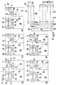
- FIG. 4 shows the function of the film buffer 1 according to FIG. 1 in schematic form.
- the individual drives have been omitted for the sake of clarity.
- a first film section 45 is wound into the film buffer 1 with the aid of the input rollers 5, 6. It is guided by the guide device 8 to the intermediate rolls 9, 10.
- the intermediate rollers 9, 10 capture the first film section 45 and wind it into the first buffer 13, at a speed that corresponds to that of a station upstream of the film buffer 1.
- the transport can also take place intermittently.
- the intermediate roller sensor 34 detects whether or not a film section is present in the area monitored by it (FIG. 4a). 4b, the first film section 45 is completely in the first buffer 13 spooled.
- the intermediate roller sensor 34 reports that there is no longer any film section in the area monitored by it.
- the drive of the intermediate rollers 9, 10 is stopped.
- FIG. 4c shows the step where the intermediate roller pair 9, 10 reverses the direction of movement of the film section 45 and conveys the film section in the direction of the buffer rolls 14, 15.
- the end of the film section 45 is now moved towards the exit rollers 20, 21.
- the guide device 8 ensures that the film end actually runs in the right direction and is not pushed back to the input rollers 5, 6.
- the buffer rollers 14, 15 preferably run at the same speed as the intermediate rollers 9, 10. If this cannot be achieved, the buffer rollers 14, 15 run at a slightly higher speed, ie they convey the film section 45 at a slightly higher speed than the intermediate rollers 9 , 10.
- the buffer roller sensor 35 detects the presence of the film section in the area monitored by it, the drive for the buffer rollers 14, 15 is stopped.
- the rewinding from the first buffer 13 into the second buffer 26 takes place at a higher speed than the rewinding of the film section into the first buffer.
- the drive 27 for the intermediate rollers 9, 10 can apply the same maximum speed during the forward and backward movement, the speed when winding out from the first buffer 13 is nevertheless considerably higher than when winding in, since the film section generally takes place during winding is only driven intermittently, especially when the exposure station upstream of the film buffer is designed as a scanner.
- the winding out of the first buffer 13 then generally takes place at a speed which is 5 to 10 times greater.
- the drive 27 for the intermediate roller pair 9, 10 can, however, also be designed such that it allows a much higher speed for winding the film section out of the first buffer 13 than for winding it.
- Fig. 5 illustrates that in the embodiment shown in Fig. 1, the buffer rollers 14, 15 and the output rollers 20, 21 each have the same direction of rotation.
- the rotation of the buffer roller is transferred to the other buffer roller 15 using two pinions 47, 48, that comb into each other.
- the output roller 21 is driven by the output roller 20, namely by two pinions 49, 50, each of which is non-rotatably connected to the two roller axes and mesh with one another.
- the output roller 20 has a toothed belt pinion 53.
- the buffer roller 14 has a toothed belt pinion 54.
- the toothed belt 33 which transmits the movement from the pair of buffer rollers 14, 15 to the output rollers 20, 21, rests on both toothed belt pinions 52, 54.
- FIG. 6a to 6e show the stations of a first film section 45 and a second film section 46 on their way through the film buffer 101, the film sections 45, 46 coming out of the film buffer 101 again in contrast to the method sequence shown in FIG they have been introduced, ie with the original beginning ahead.
- the function of the film buffer 101 according to FIGS. 6a and 6b is identical to the function of the film buffer 1 according to FIGS. 4a and 4b.
- the intermediate roller sensor 34 has determined that the film section 45 has been wound sufficiently far into the first buffer 13, i.e. that its end has been guided past the deflection edge 11 of the guide device 8, the intermediate rolls 9, 10 reverse their direction of rotation and convey the film section 45 in Direction towards the buffer rollers 14, 15.
- the piston-cylinder unit 30 can take action and open the nip 12 of the intermediate roller pair 9, 10. The buffer rollers 14, 15 can then pull the film section 45 out of the first buffer 13 without the intermediate rollers 9, 10 still having to operate.
- the buffer rollers 14, 15 convey the film along the guiding device 42 to the turning rollers 23, 24 and from there into the second buffer 26.
- the film end of the film section 45 is therefore first transported into the second buffer 26 this time.
- the first buffer 13 can be filled again with a second film section 46.
- the first film section 45 is in the second buffer 26 at this time.
- the turning roller sensor 36 detects that there is no longer any film section in the area monitored by it, the direction of rotation of the turning rolls 23, 24 is reversed and the film section 45 is transported along the guide device 42 to the exit rollers 20, 21 (FIG. 4e).
- the deflection edge 44 ensures that the original beginning of the first film section 45 is conveyed in the direction of the exit rollers 20, 21 and does not run back to the buffer rollers 14, 15.
- the first buffer Since the rewinding from the first buffer 13 into the second buffer 26 takes place at an increased speed, the first buffer is ready again after a very short time to receive a film section 46 without the feed device, for example the exposure device, which is connected upstream of the film buffer , must stop working for a long period of time.
- the deflection of the film end or the beginning of the film with the aid of the guide device 8 or the turning guide device 42 can also be done in a different way than through a deflection edge 11 or 44 take place.
- the guide device 8 or the turning guide device 42 can also have moving parts, which are reversed accordingly and fulfill the function of a switch.
- reliable guidance of the respective film section can already be achieved with the static guidance device 8 or the turning guidance device 42.
- Fig. 7 illustrates the relationship of the drives between the buffer rollers 14, 15, the output rollers 21, 22 and the turning rollers 23, 24.
- the output roller 14 always rotates in the same direction as the turning roller 23.
- the turning roller 23 always turns in the same direction as the output roller 21. It follows that the output roller 21 always rotates with the opposite orientation as the buffer roller 14. This is achieved in that the individual roller pairs, each by pinion or friction wheels 47, 48 and 49, 50th or 51, 52 are in engagement with each other, are connected by the toothed belt 41, which transmits its force with the aid of toothed belt pinions 55, 56, 57 to the individual pairs of rollers.
Landscapes
- Physics & Mathematics (AREA)
- General Physics & Mathematics (AREA)
- Projection-Type Copiers In General (AREA)
- Photographic Developing Apparatuses (AREA)
- Photographic Processing Devices Using Wet Methods (AREA)
Applications Claiming Priority (2)
| Application Number | Priority Date | Filing Date | Title |
|---|---|---|---|
| DE4028094A DE4028094C1 (fr) | 1990-09-05 | 1990-09-05 | |
| DE4028094 | 1990-09-05 |
Publications (2)
| Publication Number | Publication Date |
|---|---|
| EP0474162A2 true EP0474162A2 (fr) | 1992-03-11 |
| EP0474162A3 EP0474162A3 (en) | 1992-09-02 |
Family
ID=6413613
Family Applications (1)
| Application Number | Title | Priority Date | Filing Date |
|---|---|---|---|
| EP19910114749 Withdrawn EP0474162A3 (en) | 1990-09-05 | 1991-09-02 | Intermediate film storage device |
Country Status (5)
| Country | Link |
|---|---|
| US (1) | US5186453A (fr) |
| EP (1) | EP0474162A3 (fr) |
| JP (1) | JPH04246648A (fr) |
| DE (1) | DE4028094C1 (fr) |
| FI (1) | FI914140A7 (fr) |
Cited By (2)
| Publication number | Priority date | Publication date | Assignee | Title |
|---|---|---|---|---|
| EP0663615A3 (fr) * | 1994-01-12 | 1996-01-03 | Miles Inc | Système tampon à deux médias pourvu d'une unité d'embrayage à roue libre. |
| US6420607B1 (en) | 1997-05-01 | 2002-07-16 | 3M Innovative Properties Company | Cationically polymerizable compositions capable of being coated by electrostatic assistance |
Families Citing this family (5)
| Publication number | Priority date | Publication date | Assignee | Title |
|---|---|---|---|---|
| DE69431850T2 (de) * | 1993-08-16 | 2003-07-17 | Agfa Corp., Ridgefield Park | Verfahren und Apparat zum Zwischenspeichern von Medien |
| US5449164A (en) * | 1994-08-29 | 1995-09-12 | Xerox Corporation | Sheet inverter apparatus |
| DE19823906C2 (de) * | 1998-05-28 | 2001-06-28 | Gretag Imaging Ag | Filmmaterial-Leitanlage |
| US7866661B2 (en) * | 2007-08-29 | 2011-01-11 | Pitney Bowes Inc. | Sheet/page buffer for sheet handling apparatus |
| CN102649376B (zh) * | 2011-06-21 | 2014-04-02 | 北京京东方光电科技有限公司 | 一种打标方法及设备 |
Family Cites Families (10)
| Publication number | Priority date | Publication date | Assignee | Title |
|---|---|---|---|---|
| JPS53149332A (en) * | 1977-06-01 | 1978-12-26 | Oriental Photo Ind Co Ltd | Sheettshaped photographic paper guiding device |
| US4673176A (en) * | 1980-10-02 | 1987-06-16 | Xerox Corporation | Soft nip damping inverter |
| DE3122586A1 (de) * | 1981-06-06 | 1982-12-23 | Agfa-Gevaert Ag, 5090 Leverkusen | Vorrichtung zum entladen von roentgenfilm-kassetten |
| JPS58107540A (ja) * | 1981-12-22 | 1983-06-27 | Fuji Photo Film Co Ltd | カメラプロセサにおけるフイルム貯蔵装置 |
| GB2128593B (en) * | 1982-10-19 | 1985-08-29 | Hadland John | Web transfer between stations |
| US4817933A (en) * | 1984-10-02 | 1989-04-04 | Canon Kabushiki Kaisha | Document handling apparatus |
| JPS61109027A (ja) * | 1984-11-01 | 1986-05-27 | Fuji Photo Film Co Ltd | 印画紙保留装置 |
| US4714241A (en) * | 1986-08-04 | 1987-12-22 | Eastman Kodak Company | Recirculating document feeder |
| DE3914183A1 (de) * | 1988-05-01 | 1989-11-09 | Minolta Camera Kk | Transporteinrichtung fuer papierblaetter |
| US4993700A (en) * | 1988-11-15 | 1991-02-19 | Brandt, Inc. | Facing mechanism for sheet feeder |
-
1990
- 1990-09-05 DE DE4028094A patent/DE4028094C1/de not_active Expired - Fee Related
-
1991
- 1991-08-29 US US07/751,482 patent/US5186453A/en not_active Expired - Fee Related
- 1991-09-02 EP EP19910114749 patent/EP0474162A3/de not_active Withdrawn
- 1991-09-03 FI FI914140A patent/FI914140A7/fi unknown
- 1991-09-05 JP JP3226236A patent/JPH04246648A/ja active Pending
Cited By (3)
| Publication number | Priority date | Publication date | Assignee | Title |
|---|---|---|---|---|
| EP0663615A3 (fr) * | 1994-01-12 | 1996-01-03 | Miles Inc | Système tampon à deux médias pourvu d'une unité d'embrayage à roue libre. |
| US5785312A (en) * | 1994-01-12 | 1998-07-28 | Bayer-Agfa | Dual media buffer with over-running clutch system |
| US6420607B1 (en) | 1997-05-01 | 2002-07-16 | 3M Innovative Properties Company | Cationically polymerizable compositions capable of being coated by electrostatic assistance |
Also Published As
| Publication number | Publication date |
|---|---|
| FI914140A7 (fi) | 1992-03-06 |
| US5186453A (en) | 1993-02-16 |
| DE4028094C1 (fr) | 1992-04-02 |
| FI914140A0 (fi) | 1991-09-03 |
| JPH04246648A (ja) | 1992-09-02 |
| EP0474162A3 (en) | 1992-09-02 |
Similar Documents
| Publication | Publication Date | Title |
|---|---|---|
| DE2808700C2 (de) | Ablenkvorrichtung für Blätter mit mehreren hintereinanderliegenden Ablagefächern | |
| DE60320503T2 (de) | Verfahren und Vorrichtung zum Sammeln und Fördern von Papier, Rotationselement dafür | |
| DE4020814C2 (de) | Blattransportvorrichtung und deren Verwendung in einem Bildaufzeichnungsgerät | |
| DE2617479B2 (de) | Papiertransporteinrichtung in einem kopiergeraet | |
| DE2425207B2 (de) | Vorrichtung zum Speichern und Abgeben von Blättern | |
| DE3622187C2 (de) | Vorlagenzuführvorrichtung | |
| DE3623075A1 (de) | Blatttransportvorrichtung | |
| DE2445998C3 (de) | Aufwickelvorrichtung für bandförmiges Material | |
| DE2353851A1 (de) | Verfahren und einrichtung zur handhabung stabfoermiger gegenstaende | |
| EP0474162A2 (fr) | Appareil de stockage intermédiaire pour films | |
| DE3241574C2 (fr) | ||
| DE4237428A1 (fr) | ||
| DE19643554A1 (de) | Transportvorrichtung für fotosensitives Material | |
| DE19956693A1 (de) | Automatische Blattzuführeinrichtung für eine Vorrichtung zur Erzeugung von Bildern | |
| DE1472619A1 (de) | Schmalfilmkamera | |
| DE2445259B2 (de) | Vorrichtung zum schrittweisen transport eines bandfoermigen materials | |
| DE60109866T2 (de) | Vorrichtung zum Aufbringen von Kleber auf ein Bahnende einer Wickelrolle, eine Wickelrolle oder eine Wickelhülse | |
| DE3408376C2 (de) | Bildübertragungsvorrichtung | |
| DE2227582B2 (de) | Vorrichtung zum Falten von Bogen aus Papier, Folien od.dgl | |
| DE2202334B2 (de) | Vorrichtung zum Ablegen von dünnen, biegsamen Blättern | |
| DE3122585C2 (de) | Vorrichtung zum Entnehmen von Filmen, insbesondere Röntgenfilmen aus einem Magazin | |
| DE2645751C2 (de) | Automatische Filmeinfädelvorrichtung | |
| DE3827604C2 (fr) | ||
| DE1925039B2 (de) | Greifmechanismus für elektrofotografische Kopiermaschinen zur Beförderung von Blättern | |
| DE2337073A1 (de) | Elektrophotographische kopiermaschine |
Legal Events
| Date | Code | Title | Description |
|---|---|---|---|
| PUAI | Public reference made under article 153(3) epc to a published international application that has entered the european phase |
Free format text: ORIGINAL CODE: 0009012 |
|
| AK | Designated contracting states |
Kind code of ref document: A2 Designated state(s): BE CH DK ES FR GB IT LI NL SE |
|
| PUAL | Search report despatched |
Free format text: ORIGINAL CODE: 0009013 |
|
| AK | Designated contracting states |
Kind code of ref document: A3 Designated state(s): BE CH DK ES FR GB IT LI NL SE |
|
| 17P | Request for examination filed |
Effective date: 19920824 |
|
| 17Q | First examination report despatched |
Effective date: 19940425 |
|
| STAA | Information on the status of an ep patent application or granted ep patent |
Free format text: STATUS: THE APPLICATION IS DEEMED TO BE WITHDRAWN |
|
| 18D | Application deemed to be withdrawn |
Effective date: 19941108 |