EP0473565B1 - Dachfenster - Google Patents
Dachfenster Download PDFInfo
- Publication number
- EP0473565B1 EP0473565B1 EP19910870133 EP91870133A EP0473565B1 EP 0473565 B1 EP0473565 B1 EP 0473565B1 EP 19910870133 EP19910870133 EP 19910870133 EP 91870133 A EP91870133 A EP 91870133A EP 0473565 B1 EP0473565 B1 EP 0473565B1
- Authority
- EP
- European Patent Office
- Prior art keywords
- window
- edge
- flank
- roof window
- transversal
- Prior art date
- Legal status (The legal status is an assumption and is not a legal conclusion. Google has not performed a legal analysis and makes no representation as to the accuracy of the status listed.)
- Expired - Lifetime
Links
- 239000000463 material Substances 0.000 claims description 14
- 229910052782 aluminium Inorganic materials 0.000 claims description 6
- XAGFODPZIPBFFR-UHFFFAOYSA-N aluminium Chemical compound [Al] XAGFODPZIPBFFR-UHFFFAOYSA-N 0.000 claims description 6
- 241001074085 Scophthalmus aquosus Species 0.000 claims 3
- 239000004411 aluminium Substances 0.000 claims 1
- 230000005494 condensation Effects 0.000 description 16
- 238000009833 condensation Methods 0.000 description 16
- 238000010276 construction Methods 0.000 description 9
- 230000015572 biosynthetic process Effects 0.000 description 7
- XLYOFNOQVPJJNP-UHFFFAOYSA-N water Substances O XLYOFNOQVPJJNP-UHFFFAOYSA-N 0.000 description 6
- 239000011324 bead Substances 0.000 description 5
- 239000007787 solid Substances 0.000 description 4
- 229920002994 synthetic fiber Polymers 0.000 description 4
- 241000397426 Centroberyx lineatus Species 0.000 description 2
- 239000002470 thermal conductor Substances 0.000 description 2
- RYGMFSIKBFXOCR-UHFFFAOYSA-N Copper Chemical compound [Cu] RYGMFSIKBFXOCR-UHFFFAOYSA-N 0.000 description 1
- 239000004593 Epoxy Substances 0.000 description 1
- 239000002775 capsule Substances 0.000 description 1
- 229910052802 copper Inorganic materials 0.000 description 1
- 239000010949 copper Substances 0.000 description 1
- 230000002349 favourable effect Effects 0.000 description 1
- 239000011521 glass Substances 0.000 description 1
- 239000003365 glass fiber Substances 0.000 description 1
- 238000002347 injection Methods 0.000 description 1
- 239000007924 injection Substances 0.000 description 1
- 239000012212 insulator Substances 0.000 description 1
- 239000007788 liquid Substances 0.000 description 1
- 238000003754 machining Methods 0.000 description 1
- 238000004519 manufacturing process Methods 0.000 description 1
- 229910052751 metal Inorganic materials 0.000 description 1
- 239000002184 metal Substances 0.000 description 1
- 150000002739 metals Chemical class 0.000 description 1
- 238000000465 moulding Methods 0.000 description 1
- 230000000630 rising effect Effects 0.000 description 1
- 229910000679 solder Inorganic materials 0.000 description 1
- 229910001220 stainless steel Inorganic materials 0.000 description 1
- 239000010935 stainless steel Substances 0.000 description 1
- 230000007704 transition Effects 0.000 description 1
- 238000009423 ventilation Methods 0.000 description 1
- 238000003466 welding Methods 0.000 description 1
Images


Classifications
-
- E—FIXED CONSTRUCTIONS
- E04—BUILDING
- E04D—ROOF COVERINGS; SKY-LIGHTS; GUTTERS; ROOF-WORKING TOOLS
- E04D13/00—Special arrangements or devices in connection with roof coverings; Protection against birds; Roof drainage ; Sky-lights
- E04D13/03—Sky-lights; Domes; Ventilating sky-lights
-
- E—FIXED CONSTRUCTIONS
- E04—BUILDING
- E04D—ROOF COVERINGS; SKY-LIGHTS; GUTTERS; ROOF-WORKING TOOLS
- E04D13/00—Special arrangements or devices in connection with roof coverings; Protection against birds; Roof drainage ; Sky-lights
- E04D13/03—Sky-lights; Domes; Ventilating sky-lights
- E04D13/035—Sky-lights; Domes; Ventilating sky-lights characterised by having movable parts
- E04D13/0358—Sky-lights; Domes; Ventilating sky-lights characterised by having movable parts the parts moving, in their own plane, e.g. rolling or sliding, or moving in parallel planes with or without an additional movement, e.g. both pivoting and rolling or sliding
-
- E—FIXED CONSTRUCTIONS
- E04—BUILDING
- E04D—ROOF COVERINGS; SKY-LIGHTS; GUTTERS; ROOF-WORKING TOOLS
- E04D3/00—Roof covering by making use of flat or curved slabs or stiff sheets
- E04D3/02—Roof covering by making use of flat or curved slabs or stiff sheets of plane slabs, slates, or sheets, or in which the cross-section is unimportant
- E04D3/06—Roof covering by making use of flat or curved slabs or stiff sheets of plane slabs, slates, or sheets, or in which the cross-section is unimportant of glass or other translucent material; Fixing means therefor
-
- E—FIXED CONSTRUCTIONS
- E04—BUILDING
- E04D—ROOF COVERINGS; SKY-LIGHTS; GUTTERS; ROOF-WORKING TOOLS
- E04D3/00—Roof covering by making use of flat or curved slabs or stiff sheets
- E04D3/02—Roof covering by making use of flat or curved slabs or stiff sheets of plane slabs, slates, or sheets, or in which the cross-section is unimportant
- E04D3/06—Roof covering by making use of flat or curved slabs or stiff sheets of plane slabs, slates, or sheets, or in which the cross-section is unimportant of glass or other translucent material; Fixing means therefor
- E04D3/08—Roof covering by making use of flat or curved slabs or stiff sheets of plane slabs, slates, or sheets, or in which the cross-section is unimportant of glass or other translucent material; Fixing means therefor with metal glazing bars
- E04D2003/0812—Roof covering by making use of flat or curved slabs or stiff sheets of plane slabs, slates, or sheets, or in which the cross-section is unimportant of glass or other translucent material; Fixing means therefor with metal glazing bars the supporting section of the glazing bar consisting of one single bent or otherwise deformed sheetmetal
-
- E—FIXED CONSTRUCTIONS
- E04—BUILDING
- E04D—ROOF COVERINGS; SKY-LIGHTS; GUTTERS; ROOF-WORKING TOOLS
- E04D3/00—Roof covering by making use of flat or curved slabs or stiff sheets
- E04D3/02—Roof covering by making use of flat or curved slabs or stiff sheets of plane slabs, slates, or sheets, or in which the cross-section is unimportant
- E04D3/06—Roof covering by making use of flat or curved slabs or stiff sheets of plane slabs, slates, or sheets, or in which the cross-section is unimportant of glass or other translucent material; Fixing means therefor
- E04D3/08—Roof covering by making use of flat or curved slabs or stiff sheets of plane slabs, slates, or sheets, or in which the cross-section is unimportant of glass or other translucent material; Fixing means therefor with metal glazing bars
- E04D2003/0818—Roof covering by making use of flat or curved slabs or stiff sheets of plane slabs, slates, or sheets, or in which the cross-section is unimportant of glass or other translucent material; Fixing means therefor with metal glazing bars the supporting section of the glazing bar consisting of several parts, e.g. compound sections
Definitions
- the invention relates to a roof window, in particular a window made of aluminum, comprising a frame in which a pane is mounted, said frame comprising at least two longitudinal parts which are each connected to at least one transverse part, and where each part comprises a first and a second profile, said first and second profiles of the parts having a first open side and each comprising a first and a second raised flank connected by a first core and being arranged with their open side facing each other, said profiles being connected detachably, in at least one of the parts, by means of connecting elements, said profiles of the longitudinal parts each being provided with an edge applied to at least one side of their raised sides, the longitudinal edges of said pane being mounted, on said longitudinal parts, in a space between said applied edges disposed facing face of said profiles constituting said longitudinal parts, a first profile of the transverse part being provided with an edge applied to the first raised flank, the transverse edges of said pane being mounted, on the transverse part, in a space between said applied edge of said first profile and one end of the first sidewall raised
- Such a window for roofing is known from French Patent No. 479,838.
- the first and second profiles are connected using a connecting bar.
- the tile itself is wedged by its border between the edges of said first and second profiles.
- a known problem with roof windows, especially when aluminum is used, is the formation of condensation on the tile. This condensation is due to a bad heat exchange between the tile, a bad thermal conductor, and aluminum which is a good thermal conductor.
- longitudinal grooves in the tile were applied in the known roof window. These grooves retain by capillary action the moisture which condenses on the sheet and then conduct the condensing liquid to the lower part of the frame.
- a disadvantage of known roof windows is precisely the use of tiles provided with such grooves. Such tiles are expensive, largely prevent view through the tiles and are unattractive.
- the object of the invention is to produce a roof window where, by the construction of the chassis, the formation of condensation is combated.
- a roof window according to the invention is characterized in that said connecting elements are made of a material having a low thermal conductivity and where the end of a second flank raised from the first profile of the transverse part being disposed at a distance from the second profile of the transverse part, so that an opening is created in this place between the first and the second profile of the transverse part.
- the use of a material having a low thermal conductivity for the connecting element between the first and the second sections already takes care for a low thermal conductivity between the first and the second sections. Thanks to this already little heat is conducted to the profile disposed on the outer face which already provides a contribution to combat condensation.
- By creating more opening between the first and the second profile of the transverse part of the air can enter the space enveloped by the first and the second profile. This air will now ensure that in said space there is good ventilation thanks to which the formation of condensation will be effectively combated by the very construction of the chassis.
- a first preferred embodiment of a roof window according to the invention is characterized in that said frame comprises a segment intended to be placed at the height of a change of angle between two successive window parts, where said first profile comprises a second flank disposed opposite the first flank, which second flank forms an obtuse angle with the plane of said first core of said profile and terminates in a bearing edge.
- a change of angle between two successive parts of the window such as a change of angle in the roof line at the height of the ridge, where at the height of the transition line between two planes of a dome in the shape of pyramid, requires a suitable chassis.
- the second flank has a substantially arcuate profile. Since the segments of two successive sides meet at the height of a change of angle, two arc-shaped profiles are thus placed face to face, which will facilitate relative movements relative to each other.
- said bearing edge comprises another profile in the form of a cornice in which is applied another connecting element made of a material having a low thermal conductivity, said other profile being intended to allow said second profile of said segment to rest thereon. .
- another connecting element made of a material having a low thermal conductivity, said other profile being intended to allow said second profile of said segment to rest thereon.
- a second embodiment of a roof window according to the invention is characterized in that at least a part of said window is movable relative to a plate applied to said frame, which movable part comprises another frame which comprises at at least two longitudinal parts which are each connected to at least one transverse part and where each part comprises a third and a fourth profile having a second open side and each comprising a third and a fourth raised flank connected by a second core which third and fourth profiles are provided with another edge applied their third raised side, said third and fourth profiles being arranged face to face with their open side and their other edge and where a border of a tile mounted in said movable part is applied in another space between said other edges.
- a third preferred embodiment of a roof window according to the invention is characterized in that said plate includes an edge which is disposed at another distance from said end of a second side raised from said first profile of the transverse part, so as to create in this place another opening between said plate and said frame. A good air circulation is thus created between said opening and said other opening.
- a seal extends on the one hand between said other opening and on the other hand another edge of the second profile. The seal thus ensures that air circulation is maintained inside the chassis and there is no draft in the building where the roof window is placed.
- a post in which is applied removably another post, said other post being connected to said movable part.
- said fourth raised side is located opposite said third raised side, said fourth side of the third section overlapping that of the fourth section. This provides a solid construction.
- a tile is applied on both sides of the ridge and each tile is each time applied in a window panel for roofing. It is clear that the choice of several panels is only one embodiment and that it is also possible to have only one panel.
- the tile is made of glass or synthetic material.
- Each tile 1 is applied in a frame which has a longitudinal part 2 and a transverse part 3. Two successive tiles each have a border which is applied in the same longitudinal part.
- the tiles are either all fixed to the roof window or a part of these is applied in a mobile part 4.
- This mobile part itself comprises another frame 5 which is mobile relative to a plate 6.
- the other chassis 5 is mounted on a post 7 which is connected to the chassis at the height of the ridge.
- the post 7 slides inside another post 8 which serves as a guide for the post 7 when the part 4 is opened and closed.
- the post is moved either using of an electric motor, either manually.
- cushions are preferably applied inside the other post, which cushions are made of a material which resists wear and tear such as by example of the ertalon.
- the latter are applied to yet another post (not shown in the drawing) which is housed in the other post 8.
- the cushions are then for example applied in openings or perforations of said yet another post so that they are movable inside the latter to allow their adjustment.
- the post 7 then slides along said cushions inside said yet another beam.
- the posts 7 and 8 and said still other post are preferably rectangular in order to avoid mutual rotation of one post relative to the other. It is also possible to use round posts and to apply guide rails inside the other post which are housed inside grooves applied in the outside surface of the post.
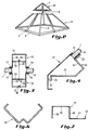
- Figure 2 shows another embodiment where the roof window is formed by a pyramid-shaped dome, the head 10 of which can be moved relative to the base part 11.
- the head 10 is mounted on a post 7.
- the base 11 has four sides formed by transverse parts and the line of demarcation between two successive planes is each time formed by a segment 9.
- the movable head is only one example of embodiment and that it is also possible to make a dome without such a movable head.
- the pyramid-shaped dome has four raised faces, but it will be clear that this is also an exemplary embodiment and that the invention also applies to domes having more or less side faces or round or arched domes or other window constructions for roofing.
- FIG. 3 A cross section of a longitudinal part 2 of a frame according to the invention is illustrated in FIG. 3.
- the longitudinal part comprises a first 12 and a second 13 profiles which have a first open side and each comprise a first 15 and a second 16 raised flank connected by a first core 14.
- the first and second raised flanks being arranged with their open side facing each other.
- the raised sides are each provided with an edge 17, 18 which is folded relative to the raised sides to which it is connected.
- the profiles intended for the longitudinal part have an edge which is folded at an angle of approximately 90 ° relative to the raised side.
- the profiles are provided with two edges 17 and 18 since they are intended to wrap on either side the edge of a tile.
- it is also possible to apply an edge to only one raised flank which is for example the case when there are no tiles on either side but only to one side of the longitudinal part.
- a longitudinal edge of the pane 1 is applied in the space between the edges 17 respectively 18 of the profiles.
- a bead 19 is applied between the tile itself and the edge in order to counter the formation of a draft.
- the first 12 and the second 13 sections are interconnected using a connecting bar 20 which is preferably provided with a thread and which is made of a material having a low thermal conductivity, such as for example a synthetic material.
- the connecting bar is made of a material having good thermal conductivity, but the transverse pieces 77, 78 to which the connecting bar is connected are made of a material having a low thermal conductivity.
- the two transverse pieces 77, 78 are connected to their respective sections. This makes it possible to incorporate the whole of the connection between the first and the second profiles inside the chassis, which on the one hand is favorable from an aesthetic point of view and on the other hand provides protection against burglary.
- the connecting bar 20 comprises two parts, each connected to a respective profile and connected together by means of a tube provided with a thread. Thanks to the use of a connecting bar, the profiles are detachably mounted, which facilitates assembly and transport.
- Figure 4 shows a sectional view of the transverse part of a chassis, which part is intended to be placed at a lower edge of the chassis.
- This part also includes a first 20 and a second profiled 21.
- the first profile 20 also has a first open side and a first core which connects the first raised side 24 to the second raised side 25.
- the second section 21 has a first raised side, one end of which ends at the level of the transverse edge of the pane 1.
- the first section 20, which is intended to be placed on the inside has an edge 22, 23 on each raised side. raised edges 24 of the first profile form a substantially right angle with the surface of the bottom, while the other raised edge 25 forms an obtuse angle with the surface of the bottom.
- the first profile perfectly joins the passage from a side wall to an inclined roof while maintaining the shape having a first open side.
- the pane 1 is again mounted between the first and the second profile and rests on the end of the first raised flank 22 and is wedged by the edge of the second profile 21.
- a bead is used for these profiles.
- the lower side part and the longitudinal part are preferably welded to each other in order to maintain a tight connection.
- FIG. 4 there is an opening 81 near the end of the first profile 20, at the edge 23 since in this location the first 20 and the second 21 profiles are not connected to each other other but placed at a distance from each other.
- This opening 81 allows air to enter the space between the first and second profiles, which air can thus circulate throughout the space between the first and second profiles of the roof window and thus combat the formation of condensation on the tile and the profile.
- FIG. 5 shows a part of the frame intended to be placed at the height of a change of angle between two successive window parts, in particular at the height of the ridge.
- this part of the frame is intended to wedge a tile on either side of the ridge and to this end this part of the chassis is substantially symmetrical with respect to the line AA '.
- this frame naturally includes only one part.
- the first profile 26 is intended to be applied on the interior side and comprises a first raised sidewall 24 which forms a substantially right angle with the surface of the bottom and an edge 30 on which the tile rests.
- a second sidewall 31 forms an obtuse angle with the bottom surface in order to maintain the profile having an open side when the angle of the roof line is modified.
- the second flank 31 also has an arcuate profile thanks to which the two flanks of neighboring profiles are perfectly pressed against one another at their ends and are pressed against each other in an elastic manner. This allows when two neighboring flanks are connected to each other that an elastic connection is made thanks to which thermal fluctuations can be better absorbed.
- the second side 31 ends in a bearing edge 32 which also has a profile having an open side.
- Each bearing edge 32 forms other raised sides disposed face to face.
- This bearing edge is used to provide an intermediate piece made of a material having a low thermal conductivity and on which the second profile 27, 28 can then be supported.
- This intermediate piece preferably has the profile of a swallow tail, which corresponds to the profile formed by the two neighboring bearing edges.
- the second profile 27, 28 also has an open side and has a first side 28 and an edge 33 which joins the upper edge of the tile.
- the second flank 34 respectively 35 joins the surface of the bottom of the neighboring profile, in order to adequately connect the neighboring profiles and thus obtain a tight ridge.
- first and second profiles Thanks to the use of first and second profiles and thanks to their geometry having an open side, a space is created by the volume enveloped by the frame in which the air introduced by the opening 81 can circulate from so that the formation of condensation on the tiles is combated and drainage for condensation is obtained.
- first and second profiles are only connected using a material having poor thermal conductivity and there is essentially air in the space delimited by the profiles having an open side, there is only a very small, practically negligible heat exchange between the first profile located inside and the second profile located outside.
- the air present forms an excellent thermal insulator.
- condensation water can easily flow along the edge of the tile and thus falls into the bottom surface of the first profile along which it can then easily be drained.
- drainage holes are preferably present in the lower part of the chassis, in particular in the first profile.
- the roof window has a movable part, such as part 4 respectively 10 illustrated in FIG. 1 respectively 2, this part is mounted on a post 7 as previously described.
- the other post 8 in which the post 7 can be moved is mounted on a support beam which is part of a plate 6.
- the ridge profiles as illustrated in FIG. 5, are replaced, at the place where this movable part is to be mounted, by other ridge profiles 36, an exemplary embodiment of which is illustrated in FIG. 6.
- the other ridge profile also has a geometry having an open side with folded edges to the raised sides and connects two side parts of the plate 6.
- the other ridge profile is substantially W-shaped in order to obtain a solid construction which is suitable for carrying the weight of the movable part.
- To further strengthen the construction preferably still applied in a number of places connecting plates which connect the raised W-shaped francs together.
- FIG. 7 shows a transverse section of the longitudinal part of the plate 6.
- This longitudinal part comprises an inverted U-shaped profile formed by the raised sides 38, 40 and the upper face 39.
- This inverted U-shaped profile is extended by a projection 41 and a short raised sidewall 42.
- the inverted U-shaped profile has such a dimension that it is applied to a second profile (FIG. 3) of a longitudinal part of the chassis illustrated in FIG. 1.
- This profile U-shaped inverted forms a saddle which is placed on the second profile of the longitudinal part of the chassis.
- the projection 41 and the sidewall 42 form a part of the plate which is intended to support the longitudinal part of the chassis of the movable part.
- the raised sides 42 of two longitudinal parts which extend substantially parallel are interconnected at the height of a lower side of the plate by means of a transverse part 53 as illustrated in FIG. 1, this allows that water flowing along the sidewall 42 or the projection 41 does not penetrate inside.
- a bead or a profile 54 in the shape of a swallow tail is applied under the transverse part 53 in order to obtain a good seal.
- the longitudinal part of the other frame of the mobile part also includes two sections, in particular a third 43, respectively a fourth section 48 as shown in FIG. 8, respectively 9.
- the third and the fourth section have a geometry having a second side open and each comprising a third 46, 51 and a fourth 44, 49 raised flank connected by a second core 45, 50.
- the third raised flank is provided with another edge 47, 52 which forms a substantially right angle with the third flank noted.
- the third and the fourth profile are mounted with their open sides facing each other, which makes it possible to form another space between the edges 47, 52 in which the edge of the tile is mounted.
- the fourth raised flanks 44 and 49 meet during assembly, which makes it possible to obtain a compatible assembly.
- the longitudinal parts are interconnected by transverse segments for example by means of welding, which transverse segments have a profile similar to that shown in FIG. 4.
- a bead is preferably applied to the other frame, in particular to the third profile, which is for example formed by a brush so that in the closed state the bead is pressed against the plate. This significantly reduces the air flow between the other chassis and the tray.
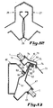
- the passage profile 53 comprises a first part 54, substantially in the shape of a U, which has a dimension which corresponds to that of the second profile 14 shown in FIG. 3. This first part 54 slides over the second profile 14 and is thus connected to it. This connection is preferably completed by providing solder points.
- Another substantially U-shaped portion 55 forms a substantially right angle with the first U-shaped portion and serves as an outer frame for a tile to be applied to the sidewall.
- FIG. 11 shows a lower part of a chassis intended for such a lateral flank.
- This lower part has two parts 56, 57.
- the part 56 is located on the inside and the tile is applied between the sidewall 58 and the sidewall 59.
- An opening 81 is also present between the first and the second sections.
- roof windows according to the invention are also applied for domes such as for example pyramid-shaped domes having three or more faces or round domes.
- profiles substantially in the form of a cornice For the pyramid-shaped dome shown in Figure 2, for the longitudinal parts 2 are used profiles as shown in Figure 3, while for the transverse parts 3 profiles as shown in Figure 4 are used.
- profiles as used in FIG. 12 are used. These latter profiles are similar to those shown in FIG. 5.
- the parts 27, 62 and 21 respectively 28, 62 and 21 are welded to each other after mounting to allow a solid construction.
- the segments at the height of the change of angle consist of profiles as shown in FIG. 12, these segments then form the ribs of the pyramid and are welded l to each other at the top.
- Figure 13 shows a sectional view at height of where the movable head 10 rests on the lower part 11.
- This lower part comprises a plate 60 which is detachably connected with a first transverse part 61 located at the upper part from the chassis of the lower part. Between the plate 60 and the first section 61 of the lower part, at the height of the bearing edge 66, another opening 83 is applied which has the same function as the opening 81 of the transverse section shown in FIG. 4.
- the first transverse part 61 comprises a profile in the form of a cornice where the edge of the tile abuts against the edge 65.
- the plate 60 rests on the first profile 61.
- the plate 60 is intended to carry the other post 8.
- the edge of the pane 1 of the lower part is located in the space between the edge 65 of the first transverse part 61 and one side 67 of the second transverse part 62.
- the other side 68 of the second transverse part 62 supports a lower edge of the head 10.
- the second transverse part comprises also a profile essentially in the form of a cornice.
- the lower edge of the frame forming part of the head comprises a fifth 63 respectively a sixth section 64.
- the fifth section comprises a strip 69 which forms a substantially right angle relative to the strip 70, which strip 70 forms an obtuse angle with a strip 71 which, when the head is in the closed position, rests on the other side 68.
- the strip 71 is extended by a strip 72 which is connected to the sixth profile at the height of a point of inclination between the strips 73, 74 of the sixth section 64, which additionally comprises the strips 75 and 76.
- the strip 73 extends substantially parallel to the flank 67 and forms with respect to the strip 72 a projection, by means of which this strip 73 serves as it were to discharge and ensures that the condensation water lands on the pane 1 of the lower part along which this water can then be discharged along the gutter-shaped profiles.
- a seal 82 for example made of rubber, is applied at the height of the plate 60 and of the second profile 62.
- a first end of the seal 82 is applied in the other opening 83 and bears in this place against the lower edge of the plate 60.
- a second end of the joint which preferably has a geometry in the form of a half cylinder, is applied to the side 68 of the second profile 62 so that when the head 10 is in the closed state, it this leans against this second end.
- the seal ensures that, in the closed state, there is no water which can penetrate inward via the sidewall 68.
- the seal also ensures that the air which circulates in the space between the first and the second sections 62, as well as in the space enveloped by the plate 60 does not escape along the plate 60 and would thus cause an air current in the space covered by the dome.
- This last aspect is mainly achieved thanks to the geometry of the joint at its so-called first end.
- a border of the tile forming part of the head is applied in the space between the strips 63 and 76 and bears against the strip 70.
- condensation forms on the interior part of the tile, this can arise from the along the tile and will arrive in the ledge formed by the bands 69 and 70 which are provided with evacuation holes.
- All profiles are produced by folding plates, preferably aluminum plates, which allows easy and inexpensive machining. It will be clear that other materials than aluminum can also be used, such as for example copper or stainless steel and that alongside metals it is also possible to use synthetic materials such as epoxy which may or may not be reinforced with glass fibers.
- the different profiles and segments are, when synthetic materials are used, for example manufactured by injection or molding. To manufacture the above profiles, it is of course also possible to use drawn profiles.
- the invention is of course applicable to other window constructions such as windows for walls.
Landscapes
- Engineering & Computer Science (AREA)
- Architecture (AREA)
- Civil Engineering (AREA)
- Structural Engineering (AREA)
- Roof Covering Using Slabs Or Stiff Sheets (AREA)
- Seal Device For Vehicle (AREA)
Claims (14)
- Dachfenster, insbesondere aus Aluminium hergestellt, mit einem Rahmen, in dem eine Scheibe (1) eingesetzt istder genannte Rahmen umfasst mindestens zwei Längsteile (2), die jeweils mit mindestens einem Querteil (3) verbunden sind, und wo jedes Teil ein erstes (12; 20; 26; 61) und ein zweites Profilelement (13; 21; 27; 28; 62) umfasst; die ersten und zweiten Profilelemente der Teile umfassen eine erste offene Seite und eine erste (15; 24) und eine zweite hochgezogene Flanke (16; 25; 31), die mit einer ersten Innenseite verbunden und mit ihren offenen Seiten gegenüberliegend angeordnet sind,die genannten Profilelemente sind mindestens in einem der Teile mit Verbindungselementen (20) aus einem Werkstoff mit geringer Wärmeleitfähigkeit abmontierbar miteinander verbundendie genannten Profilelemente der Längsteile umfassen jeweils eine Kante (17; 18; 30) an mindestens einer ihrer hochgezogenen Flanken (15; 16; 24; 25; 31), die Längskanten der genannten Scheibe sind in den genannten Längsteilen in einem Zwischenraum eingesetzt, zwischen den genannten Kanten, die gegenüber den die Längsteile bildenden Profilelementen liegen,ein erstes Profilelement (20) des Querteiles umfasst eine Kante (22), die an der ersten hochgezogenen Flanke (24) angesetzt ist,die Querkanten der Scheibe sind am Querteil eingesetzt, in einem Raum zwischen der am ersten Profilelement (20) angesetzten Kante (22) und einem Ende der ersten hochgezogenen Flanke des zweiten Profilelementes (21) des Querteiles,das Ende einer zweiten hochgezogenen Kante des ersten Profilelementes (20) des Querteiles ist auf einem Abstand zum zweiten Profilelement (21) des Querteiles angeordnet, so dass an dieser Stelle eine Öffnung zwischen dem ersten und zweiten Profilelement des Querteiles gebildet wird.
- Dachfenster nach Anspruch 1, dadurch gekennzeichnet, dass der Rahmen ein Segment umfasst, das auf der Höhe eines Winkelwechsels zwischen zwei aufeinanderfolgende Fensterteile einsetzbar ist, wo das erste Profilelement (26) eine zweite hochgezogene Flanke (31) umfasst die gegenüber die erste hochgezogene Flanke (24) aufgestellt is, welche zweite hochgezogene Flanke mit der Ebene des ersten Innenblattes einen stumpfen Winkel bildet und mit einer Tragkante (32) endet.
- Dachfenster nach Anspruch 2, dadurch gekennzeichnet, dass jede Tragkante (32) ein weiteres Profilelement umfasst, die weiteren Profilelemente bilden weitere Flanken, die gegenüberliegend angeordnet sind.
- Dachfenster nach Anspruch 2, dadurch gekennzeichnet, dass die zweite hochgezogene Flanke (31) ein im wesentlichen bogenförmiges Profilelement umfasst.
- Dachfenster nach Anspruch 3, dadurch gekennzeichnet, dass ein weiteres aus einem Werkstoff mit geringer Wärmeleitfähigkeit gefertigtes Verbindungselement an der genannten Tragkante (32) mit dem weiteren Profilelement eingesetzt ist, das gennante weitere Profilelement dient zur Auflage des genannten zweiten Profilelementes (27; 28) des genannten Segmentes.
- Dachfenster nach einem der Ansprüche 1 bis 5, dadurch gekennzeichnet, dass mindestens ein Teil (4; 10) des genannten Fensters bezüglich einer an der genannten Rahmen eingesetzten Platte (6; 60) verschiebbar ist, wobei dieses verschiebbare Teil einen weiteren Rahmen (5) umfasst, der mindestens zwei Längsteile umfasst, der jeweils mit mindestens einem Querteil verbunden sind, und wo jedes Teil ein drittes (43) und ein viertes Profilelement (48) mit einer offenen Seite umfasst und jedes eine dritte (46; 51) und eine vierte hochgezogene Flanke (44, 49), die durch ein zweites Innenblatt (45; 50) verbunden sind umfasst, wobei die dritte (43) und vierte Profilelemente eine an ihrer dritten hochgezogenen Flanke (46, 51) weitere Kante (47, 52) enhalt, genannte dritte und vierte Profilelemente sind mit ihrer offenen Seite und der weiteren Kante gegenüberliegend angeordnet, und wobei eine Kante der im verschiebbaren Teil montierten Scheibe im einem weiteren Raum zwischen den genannten weiteren Kanten eingesetzt ist.
- Dachfenster nach Anspruch 6, dadurch gekennzeichnet eine Dichtung (82), die zwischen den genannten Rahmen und den besagten weiteren Rahmen montiert ist.
- Dachfenster nach Anspruch 6 oder 7, dadurch gekennzeichnet, dass die genannte Platte (6; 60) eine Kante (66) umfasst, die auf einem weiteren Abstand vom genannten Ende einer zweiten hochgezogenen Flanke des ersten Profilelementes des Querteiles angeordnet ist, so dass an dieser Stelle eine weitere Öffnung zwischen dieser Platte und den genannte Rahmen geschaffen wird.
- Dachfenster nach den Ansprüchen 7 und 8, dadurch genkennzeichnet, dass die genannte Dichtung (82) sich einerseitz zwischen der genannte weiteren Öffnung und anderseitz einer weiteren Kante des zweiten Profilelementes erstreckt,
- Dachfenster nach einem der Ansprüche 6 bis 9, dadurch gekennzeichnet, dass an einem an der Platte angebrachten Querteil ein Pfosten (8) montiert ist, in dem ein weiterer abmontierbarer Pfosten (7) eingesetzt ist, wobei dem weiteren Pfosten mit dem verschiebbaren Teil verbunden ist.
- Dachfenster nach Anspruch 10, dadurch gekennzeichnet, dass das genannte Querprofil (36) einen im wesentlichen w-förmigen Teil umfasst, der an den Enden mit Kanten versehen ist, die aufeinander ausgerichtet sind.
- Dachfenster nach einem der Ansprüche 6 bis 11, daduch gekennzeichnet, dass der genannte verschiebbare Teil Bestandteil eines Satteldaches ist und an jenseitz des Firstes erstreckt.
- Dachfenster nach den Ansprüchen 10 und 12 oder 11 und 12, daduch gekennzeichnet, dass das genannten Querprofilelement zum Einsatz auf wesentliche Firsthöhe geplant ist.
- Dachfenster nach Anspruch 6, dadurch gekennzeichnet, dass die genannte vierte hochgezogene Flanke (44; 49) gegenüber der genannten dritten hochgezogenen Flanke (46, 51) liegt, die genannte vierte Flanke des dritten Profilelementes überlappt die Flanke des vierten Profilelementes.
Applications Claiming Priority (2)
| Application Number | Priority Date | Filing Date | Title |
|---|---|---|---|
| BE9000825A BE1004549A5 (nl) | 1990-08-28 | 1990-08-28 | Dakraamconstructie. |
| BE9000825 | 1990-08-28 |
Publications (2)
| Publication Number | Publication Date |
|---|---|
| EP0473565A1 EP0473565A1 (de) | 1992-03-04 |
| EP0473565B1 true EP0473565B1 (de) | 1997-04-09 |
Family
ID=3884912
Family Applications (1)
| Application Number | Title | Priority Date | Filing Date |
|---|---|---|---|
| EP19910870133 Expired - Lifetime EP0473565B1 (de) | 1990-08-28 | 1991-08-28 | Dachfenster |
Country Status (3)
| Country | Link |
|---|---|
| EP (1) | EP0473565B1 (de) |
| BE (1) | BE1004549A5 (de) |
| DE (1) | DE69125551T2 (de) |
Families Citing this family (2)
| Publication number | Priority date | Publication date | Assignee | Title |
|---|---|---|---|---|
| AT403827B (de) * | 1995-03-01 | 1998-05-25 | Pagitz Manfred Dipl Ing | Dachflächenfenster |
| NL2030843B1 (nl) | 2022-02-08 | 2023-08-14 | Hak4T Facilities B V | Lichtstraat |
Family Cites Families (17)
| Publication number | Priority date | Publication date | Assignee | Title |
|---|---|---|---|---|
| FR479838A (fr) * | 1915-09-27 | 1916-05-17 | Pennsylvania Wire Glass Compan | Perfectionnements dans les chassis vitrés inclinés |
| US1548083A (en) * | 1921-09-24 | 1925-08-04 | Pittsburgh Plate Glass Co | Store-front construction |
| US1922410A (en) * | 1930-03-26 | 1933-08-15 | Young Christian | Ventilating skylight |
| US1926647A (en) * | 1931-07-10 | 1933-09-12 | Kawneer Co | Store front construction |
| US2842073A (en) * | 1954-09-29 | 1958-07-08 | Sanford K Huston | Skylight |
| US3381434A (en) * | 1965-05-14 | 1968-05-07 | Pittsburgh Plate Glass Co | Glass division bar |
| GB1272483A (en) * | 1969-07-09 | 1972-04-26 | Ruth Lisbeth Kallin | A roof window having a pyramidal frame construction |
| FR2231827A1 (en) * | 1973-06-04 | 1974-12-27 | Menez Louis | Demountable pitched roof made from plastics laminated panels - is formed from three basic elements with variable size base |
| DE3009324A1 (de) * | 1980-03-11 | 1981-09-17 | Helge B. Dipl.-Ing. 4000 Düsseldorf Cohausz | Rahmen zur schraegen verglasung von raeumen |
| BE894876A (fr) * | 1982-10-29 | 1983-02-14 | Hoviplast S P R L | Chassis de toiture en profils metalliques notamment pour serre ou veranda |
| GB2136473B (en) * | 1983-03-15 | 1987-05-20 | Gra Mar Building Products Limi | Roofspace ventilation device |
| IT1171220B (it) * | 1983-08-03 | 1987-06-10 | Aldo Galante | Profilato tubolare composito con ponte termoisolante in particolare per telai e controtelai di serramenti e simili |
| AU565444B2 (en) * | 1983-10-13 | 1987-09-17 | H.H. Robertson (Australia) Pty. Limited | Drainage channel system |
| DE3510742A1 (de) * | 1985-03-25 | 1986-09-25 | Manfred 5905 Freudenberg Hoffmann | Haltevorrichtung fuer eine glaswand bildende verglasungen |
| FR2584769B1 (fr) * | 1985-07-12 | 1989-11-03 | Audo Daniel | Panneaux d'eclairement de locaux ou analogues, a ouverture rapide automatique, comportant plusieurs sections manoeuvrees simultanement |
| US4683687A (en) * | 1986-02-10 | 1987-08-04 | Crider Brian D | View expansion enclosure with venting means |
| DE8619569U1 (de) * | 1986-07-22 | 1986-09-18 | Julius & August Erbslöh GmbH + Co, 5620 Velbert | Gewächshaus |
-
1990
- 1990-08-28 BE BE9000825A patent/BE1004549A5/nl not_active IP Right Cessation
-
1991
- 1991-08-28 EP EP19910870133 patent/EP0473565B1/de not_active Expired - Lifetime
- 1991-08-28 DE DE1991625551 patent/DE69125551T2/de not_active Expired - Fee Related
Also Published As
| Publication number | Publication date |
|---|---|
| BE1004549A5 (nl) | 1992-12-08 |
| EP0473565A1 (de) | 1992-03-04 |
| DE69125551D1 (de) | 1997-05-15 |
| DE69125551T2 (de) | 1997-11-13 |
Similar Documents
| Publication | Publication Date | Title |
|---|---|---|
| EP3115525B1 (de) | Verstellbare und isolierende blende für eine sonnenschutzanlage | |
| CH621189A5 (de) | ||
| EP0239141A1 (de) | Schiebedach, insbesondere für Veranda, und Profile zur Ausführung | |
| EP0559292B1 (de) | Anschlusselement für Bauprofile und Konstruktionen, die mittels solcher Anschlusselemente verbundene Bauprofile enthalten | |
| FR3028539A1 (fr) | Lame orientable pour toiture exterieure et un dispositif de toiture exterieure muni desdites lames | |
| FR2576955A1 (fr) | Dispositif de couverture d'espaces ou de surfaces, tel que par exemple une piscine | |
| EP0473565B1 (de) | Dachfenster | |
| EP2406093B1 (de) | Profil für das abdeckelement einer ladefläche eines fahrzeugs und zugehöriges abdeckelement | |
| EP3784512B1 (de) | Dichtungsleiste für ein fenster | |
| EP1028217A1 (de) | Fensterrahmen und Verfahren zu seiner Herstellung | |
| EP4148202A1 (de) | Pergola mit verbessertem schutz gegen das eindringen von wasser und/oder wind, die geeignet ist, um licht in den von der pergola geschützten raum zu lenken | |
| FR2528103A1 (fr) | Toiture de veranda et chassis modulaire pour sa realisation | |
| FR2813624A1 (fr) | Profile de raccord et d'etancheite, dispositif de raccord, panneau a structure sandwich, et ensemble de facade, de cloison ou de couverture | |
| FR2713540A1 (fr) | Joint de soudure pour pièces creuses. | |
| EP0172770A1 (de) | Bedeckungsanlage für Räume oder Oberflächen, z.B. für Schwimmbäder | |
| FR2700793A1 (fr) | Lucarne perfectionnée. | |
| FR2781511A1 (fr) | Abri telescopique | |
| FR2522357A1 (fr) | Lame de volet roulant | |
| BE1000815A3 (fr) | Element d'aeration pour comble en pente. | |
| CH697325B1 (fr) | Mur de façade. | |
| EP0670408B1 (de) | Deflektor für den unteren Querbalken eines Tür- oder Fensterrahmens oder dergleichen | |
| FR2489395A1 (fr) | Element autoportant pour une toiture de batiment, son procede de fabrication et installation pour la mise en oeuvre dudit procede | |
| FR2479888A1 (fr) | Fenetre ou porte coulissante | |
| FR2491599A1 (fr) | Capteur solaire utilisant l'air comme fluide caloporteur, et ses composants | |
| FR2960048A1 (fr) | Paroi formee d'une pluralite de panneaux solaires juxtaposes, comportant des moyens d'isolation thermique, et procede de fabrication d'une telle paroi |
Legal Events
| Date | Code | Title | Description |
|---|---|---|---|
| PUAI | Public reference made under article 153(3) epc to a published international application that has entered the european phase |
Free format text: ORIGINAL CODE: 0009012 |
|
| AK | Designated contracting states |
Kind code of ref document: A1 Designated state(s): BE CH DE FR GB IT LI NL |
|
| 17P | Request for examination filed |
Effective date: 19920813 |
|
| 17Q | First examination report despatched |
Effective date: 19931125 |
|
| GRAG | Despatch of communication of intention to grant |
Free format text: ORIGINAL CODE: EPIDOS AGRA |
|
| GRAH | Despatch of communication of intention to grant a patent |
Free format text: ORIGINAL CODE: EPIDOS IGRA |
|
| GRAH | Despatch of communication of intention to grant a patent |
Free format text: ORIGINAL CODE: EPIDOS IGRA |
|
| GRAA | (expected) grant |
Free format text: ORIGINAL CODE: 0009210 |
|
| AK | Designated contracting states |
Kind code of ref document: B1 Designated state(s): BE CH DE FR GB IT LI NL |
|
| PG25 | Lapsed in a contracting state [announced via postgrant information from national office to epo] |
Ref country code: IT Free format text: LAPSE BECAUSE OF FAILURE TO SUBMIT A TRANSLATION OF THE DESCRIPTION OR TO PAY THE FEE WITHIN THE PRE;WARNING: LAPSES OF ITALIAN PATENTS WITH EFFECTIVE DATE BEFORE 2007 MAY HAVE OCCURRED AT ANY TIME BEFORE 2007. THE CORRECT EFFECTIVE DATE MAY BE DIFFERENT FROM THE ONE RECORDED.SCRIBED TIME-LIMIT Effective date: 19970409 Ref country code: GB Effective date: 19970409 |
|
| REG | Reference to a national code |
Ref country code: CH Ref legal event code: EP |
|
| REF | Corresponds to: |
Ref document number: 69125551 Country of ref document: DE Date of ref document: 19970515 |
|
| REG | Reference to a national code |
Ref country code: CH Ref legal event code: NV Representative=s name: E. BLUM & CO. PATENTANWAELTE |
|
| GBV | Gb: ep patent (uk) treated as always having been void in accordance with gb section 77(7)/1977 [no translation filed] |
Effective date: 19970409 |
|
| PLBE | No opposition filed within time limit |
Free format text: ORIGINAL CODE: 0009261 |
|
| STAA | Information on the status of an ep patent application or granted ep patent |
Free format text: STATUS: NO OPPOSITION FILED WITHIN TIME LIMIT |
|
| 26N | No opposition filed | ||
| PGFP | Annual fee paid to national office [announced via postgrant information from national office to epo] |
Ref country code: CH Payment date: 19980716 Year of fee payment: 8 |
|
| PG25 | Lapsed in a contracting state [announced via postgrant information from national office to epo] |
Ref country code: LI Free format text: LAPSE BECAUSE OF NON-PAYMENT OF DUE FEES Effective date: 19990831 Ref country code: CH Free format text: LAPSE BECAUSE OF NON-PAYMENT OF DUE FEES Effective date: 19990831 |
|
| REG | Reference to a national code |
Ref country code: CH Ref legal event code: PL |
|
| PGFP | Annual fee paid to national office [announced via postgrant information from national office to epo] |
Ref country code: FR Payment date: 20020812 Year of fee payment: 12 |
|
| PGFP | Annual fee paid to national office [announced via postgrant information from national office to epo] |
Ref country code: NL Payment date: 20020814 Year of fee payment: 12 |
|
| PGFP | Annual fee paid to national office [announced via postgrant information from national office to epo] |
Ref country code: DE Payment date: 20020821 Year of fee payment: 12 |
|
| PG25 | Lapsed in a contracting state [announced via postgrant information from national office to epo] |
Ref country code: NL Free format text: LAPSE BECAUSE OF NON-PAYMENT OF DUE FEES Effective date: 20040301 |
|
| PG25 | Lapsed in a contracting state [announced via postgrant information from national office to epo] |
Ref country code: DE Free format text: LAPSE BECAUSE OF NON-PAYMENT OF DUE FEES Effective date: 20040302 |
|
| PG25 | Lapsed in a contracting state [announced via postgrant information from national office to epo] |
Ref country code: FR Free format text: LAPSE BECAUSE OF NON-PAYMENT OF DUE FEES Effective date: 20040430 |
|
| NLV4 | Nl: lapsed or anulled due to non-payment of the annual fee |
Effective date: 20040301 |
|
| REG | Reference to a national code |
Ref country code: FR Ref legal event code: ST |
|
| PGFP | Annual fee paid to national office [announced via postgrant information from national office to epo] |
Ref country code: BE Payment date: 20080901 Year of fee payment: 18 |
|
| BERE | Be: lapsed |
Owner name: M & W *DE PAEPE Effective date: 20090831 |
|
| PG25 | Lapsed in a contracting state [announced via postgrant information from national office to epo] |
Ref country code: BE Free format text: LAPSE BECAUSE OF NON-PAYMENT OF DUE FEES Effective date: 20090831 |