EP0473534B1 - Permanent magnet rotor and motor - Google Patents
Permanent magnet rotor and motor Download PDFInfo
- Publication number
- EP0473534B1 EP0473534B1 EP91630049A EP91630049A EP0473534B1 EP 0473534 B1 EP0473534 B1 EP 0473534B1 EP 91630049 A EP91630049 A EP 91630049A EP 91630049 A EP91630049 A EP 91630049A EP 0473534 B1 EP0473534 B1 EP 0473534B1
- Authority
- EP
- European Patent Office
- Prior art keywords
- rotor
- field section
- longitudinally extending
- set forth
- strips
- Prior art date
- Legal status (The legal status is an assumption and is not a legal conclusion. Google has not performed a legal analysis and makes no representation as to the accuracy of the status listed.)
- Expired - Lifetime
Links
Images

Classifications
-
- H—ELECTRICITY
- H02—GENERATION; CONVERSION OR DISTRIBUTION OF ELECTRIC POWER
- H02K—DYNAMO-ELECTRIC MACHINES
- H02K1/00—Details of the magnetic circuit
- H02K1/06—Details of the magnetic circuit characterised by the shape, form or construction
- H02K1/22—Rotating parts of the magnetic circuit
-
- H—ELECTRICITY
- H02—GENERATION; CONVERSION OR DISTRIBUTION OF ELECTRIC POWER
- H02K—DYNAMO-ELECTRIC MACHINES
- H02K29/00—Motors or generators having non-mechanical commutating devices, e.g. discharge tubes or semiconductor devices
- H02K29/06—Motors or generators having non-mechanical commutating devices, e.g. discharge tubes or semiconductor devices with position sensing devices
- H02K29/08—Motors or generators having non-mechanical commutating devices, e.g. discharge tubes or semiconductor devices with position sensing devices using magnetic effect devices, e.g. Hall-plates, magneto-resistors
-
- H—ELECTRICITY
- H02—GENERATION; CONVERSION OR DISTRIBUTION OF ELECTRIC POWER
- H02K—DYNAMO-ELECTRIC MACHINES
- H02K1/00—Details of the magnetic circuit
- H02K1/06—Details of the magnetic circuit characterised by the shape, form or construction
- H02K1/22—Rotating parts of the magnetic circuit
- H02K1/27—Rotor cores with permanent magnets
- H02K1/2706—Inner rotors
- H02K1/272—Inner rotors the magnetisation axis of the magnets being perpendicular to the rotor axis
- H02K1/274—Inner rotors the magnetisation axis of the magnets being perpendicular to the rotor axis the rotor consisting of two or more circumferentially positioned magnets
- H02K1/2753—Inner rotors the magnetisation axis of the magnets being perpendicular to the rotor axis the rotor consisting of two or more circumferentially positioned magnets the rotor consisting of magnets or groups of magnets arranged with alternating polarity
- H02K1/278—Surface mounted magnets; Inset magnets
-
- H—ELECTRICITY
- H02—GENERATION; CONVERSION OR DISTRIBUTION OF ELECTRIC POWER
- H02K—DYNAMO-ELECTRIC MACHINES
- H02K1/00—Details of the magnetic circuit
- H02K1/06—Details of the magnetic circuit characterised by the shape, form or construction
- H02K1/22—Rotating parts of the magnetic circuit
- H02K1/27—Rotor cores with permanent magnets
- H02K1/2706—Inner rotors
- H02K1/272—Inner rotors the magnetisation axis of the magnets being perpendicular to the rotor axis
- H02K1/2726—Inner rotors the magnetisation axis of the magnets being perpendicular to the rotor axis the rotor consisting of a single magnet or two or more axially juxtaposed single magnets
-
- H—ELECTRICITY
- H02—GENERATION; CONVERSION OR DISTRIBUTION OF ELECTRIC POWER
- H02K—DYNAMO-ELECTRIC MACHINES
- H02K11/00—Structural association of dynamo-electric machines with electric components or with devices for shielding, monitoring or protection
- H02K11/20—Structural association of dynamo-electric machines with electric components or with devices for shielding, monitoring or protection for measuring, monitoring, testing, protecting or switching
- H02K11/21—Devices for sensing speed or position, or actuated thereby
- H02K11/215—Magnetic effect devices, e.g. Hall-effect or magneto-resistive elements
-
- H—ELECTRICITY
- H02—GENERATION; CONVERSION OR DISTRIBUTION OF ELECTRIC POWER
- H02K—DYNAMO-ELECTRIC MACHINES
- H02K2201/00—Specific aspects not provided for in the other groups of this subclass relating to the magnetic circuits
- H02K2201/06—Magnetic cores, or permanent magnets characterised by their skew
-
- H—ELECTRICITY
- H02—GENERATION; CONVERSION OR DISTRIBUTION OF ELECTRIC POWER
- H02K—DYNAMO-ELECTRIC MACHINES
- H02K2213/00—Specific aspects, not otherwise provided for and not covered by codes H02K2201/00 - H02K2211/00
- H02K2213/03—Machines characterised by numerical values, ranges, mathematical expressions or similar information
Definitions
- This invention relates to permanent magnet motors and more particularly to such motors which minimize cogging and simplify rotor position sensing.
- Cogging is a variation in motor torque caused by variations in magnetic flux due to alignment of the rotor and the stator teeth at various positions of the rotor. This effect can reduce the efficiency and reliability of the motor.
- the object of the present invention is the provision of an improved rotor and motor which minimizes cogging and is relatively simple in construction; i.e. uses a common sensor, maintains optimum sensor position for maximum motor performance without requiring physical adjustment of the sensor.
- the rotor and motor should have equivalent operation to that of rotors with standard skews yet which allows the sensor field to be located anywhere in the skew angle.
- the permanent magnet rotor includes a main rotor field section and a sensor field section, each extending longitudinally along the rotor.
- the sensor field section is shorter than the main rotor field section and is disposed at one end of said main rotor field section.
- the sensor field section is magnetized in circumferentially disposed parallel strips of alternating magnetic polarity which extend around the rotor.
- the main rotor field section has longitudinally extending strips of alternating magnetic polarity which are skewed in a predetermined pattern, all of said longitudinally extending strips being skewed in the same predetermined pattern.
- the predetermined pattern includes a first portion in which each longitudinally extending strip runs generally at a first predetermined non-zero angle with respect to the longitudinal axis of the rotor, a second portion in which each longitudinally extending strip runs at a second predetermined non-zero angle with respect to the longitudinal axis of the rotor, and a third portion in which each longitudinally extending strip runs at the first predetermined non-zero angle with respect to the longitudinal axis of the rotor.
- the first and second predetermined non-zero angles are of opposite sign.
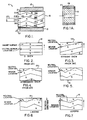
- Motor 11 includes a stator 13 having a central bore in which a permanent magnet rotor 15 is mounted for rotation.
- a Hall effect sensor 17 is disposed adjacent one end of the rotor to sense the relative rotational position of rotor 15.
- the stator and Hall effect sensor are conventional.
- Rotor 15 is not conventional. It is divided into two parts: a main rotor field section 19 and a sensor field section 21, both of which extend longitudinally along the rotor. Sensor field section 21 is substantially shorter than the main rotor field section and is disposed at one end of main rotor field section 19. A motor shaft 23, secured to rotor 15, is also shown in Fig. 1.
- the sensor field section is magnetized in circumferentially disposed parallel strips of alternating magnetic polarity including strips 21A, 21B, 21C and 21D, which strips are generally parallel to the longitudinal axis of the rotor. It should be appreciated that the boundaries between adjacent strips of the sensor field section are detected by the Hall effect sensor so that the rotational position of rotor 15 can be determined.
- Main rotor field section 19 also has longitudinally extending strips of alternating magnetic polarity, labelled 19A, 19B, 19C, and 19D.
- the main field section longitudinally extending strips are integral with the sensor field section strips.
- Each main field section strip is skewed in a predetermined pattern in which a first portion 25 runs generally at a first predetermined non-zero angle with respect to the longitudinal axis of the rotor, a second portion 27 runs generally at a second predetermined non-zero angle with respect to the longitudinal axis of the rotor, and a third portion 29 runs generally at the first predetermined non-zero angle with respect to the longitudinal axis of the rotor.
- the first and second predetermined non-zero angles are of opposite sign and generally equal in magnitude.
- This particular skewing arrangement has several advantages over conventional skewing patterns and over an unskewed rotor.
- the unskewed rotor, labelled 31, (Fig. 2) for example has the advantage that the neutral locations for the rotor correspond to the boundaries between adjacent strips of magnetization.
- This design is subject to cogging, however. It is also not a simple matter to incorporate leading or lagging switching if that is desired.
- the straight skew rotor labelled 33 (Fig. 3), solves the cogging problem, but at the expense of having the neutral location no longer correspond to the location at which the sensor detects a boundary.
- the system shown in Fig. 3 inherently has a lagging response, given the direction of rotation indicated by the arrow. If this amount of lag is not that desired, however, it can be fairly complicated to provide the required lag (or lead).
- the herringbone skew rotor labelled 35 (Fig. 4), has the same advantages and disadvantages discussed above in connection with the straight skew rotor.
- Rotor 15 (Fig. 5) of the present invention solves the cogging problem, and the difficulties associated with the rotors of Figs. 3 and 4. Because of the unique structure of the rotor skewing, the neutral locations of the rotor fall precisely on the boundaries between the sensor field section strips. As a result, no compensation for sensor position is required.
- Fig. 6 shows how the skew pattern of the present invention can be changed to provide for lag
- Fig. 7 illustrates the same thing for lead.
- Fig. 8 illustrates the boundary between adjacent strips for a rotor without lead or lag.
- the boundary between sensor field strips, labelled 41 lies on the neutral location 43.
- the neutral location is a line along which the average magnetization, measured over the main rotor field length, is zero.
- the maximum circumferential distances between the sensor field boundary 41 and the main rotor field boundary, labelled H1 and H2, are equal. Since the main rotor field boundary is symmetric with respect to the neutral location, this requirement is assured by having the sensor field boundary 41 line along the neutral location 43.
- Fig. 9 lead or lag is easily incorporated into rotor 15 by simply moving the position of the sensor field boundary as desired and shifting the curve representing the main rotor field boundary in the direction shown to match the new position of the sensor field boundary. For example, assuming rotation in the direction indicated by the arrow in Fig. 9, rotor 15 would have a leading response. The curve of Fig. 8 is shifted to the left to correspond to this new sensor field boundary position. Note that this shifting leaves the neutral location and boundary portion 27 unchanged. It simply takes part of portion 25 and adds it to the end of portion 29.
- the boundary between the two strips of the sensor field section corresponding to a predetermined pair of longitudinally extending strips of the main rotor field section is circumferentially offset from the neutral line associated with said predetermined pair of longitudinally extending strips to provide the desired lead or lag.
- any desired lead or lag is easily incorporated into the rotor without requiring any change in the position of the sensing device itself.
- Second portion 27 is always disposed between first portion 25 and third portion 29 with the second portion starting at one end of the first portion and ending at one end of the third portion.
- Second portion 27 constitutes half the main rotor field length, while portions 25 and 29 make up the other half.
- second portion 27 is longer than either of the first and third portions and is substantially equal to their sum.
- the circumferential extent of second portion 27, which is H1 plus H2 generally equals the skew angle of the rotor.
Landscapes
- Engineering & Computer Science (AREA)
- Power Engineering (AREA)
- Microelectronics & Electronic Packaging (AREA)
- Brushless Motors (AREA)
- Permanent Field Magnets Of Synchronous Machinery (AREA)
- Permanent Magnet Type Synchronous Machine (AREA)
Applications Claiming Priority (2)
| Application Number | Priority Date | Filing Date | Title |
|---|---|---|---|
| US07/575,366 US5034642A (en) | 1990-08-30 | 1990-08-30 | Permanent magnet rotor and motor |
| US575366 | 1990-08-30 |
Publications (3)
| Publication Number | Publication Date |
|---|---|
| EP0473534A2 EP0473534A2 (en) | 1992-03-04 |
| EP0473534A3 EP0473534A3 (en) | 1993-06-09 |
| EP0473534B1 true EP0473534B1 (en) | 1995-10-18 |
Family
ID=24300029
Family Applications (1)
| Application Number | Title | Priority Date | Filing Date |
|---|---|---|---|
| EP91630049A Expired - Lifetime EP0473534B1 (en) | 1990-08-30 | 1991-08-13 | Permanent magnet rotor and motor |
Country Status (7)
| Country | Link |
|---|---|
| US (1) | US5034642A (ko) |
| EP (1) | EP0473534B1 (ko) |
| JP (1) | JP3526879B2 (ko) |
| KR (1) | KR100256989B1 (ko) |
| BR (1) | BR9103527A (ko) |
| DE (1) | DE69113934T2 (ko) |
| ES (1) | ES2078491T3 (ko) |
Cited By (1)
| Publication number | Priority date | Publication date | Assignee | Title |
|---|---|---|---|---|
| EP2378627A1 (de) | 2010-04-13 | 2011-10-19 | ebm-papst Mulfingen GmbH & Co. KG | Elektromotor |
Families Citing this family (47)
| Publication number | Priority date | Publication date | Assignee | Title |
|---|---|---|---|---|
| JP2826156B2 (ja) * | 1990-03-15 | 1998-11-18 | イビデン株式会社 | スピンドルモータ |
| US5260618A (en) * | 1991-11-25 | 1993-11-09 | Seagate Technology, Inc. | Space optimization voice coil motor for disc drives |
| FR2685567B1 (fr) * | 1991-12-20 | 1997-06-06 | Valeo Systemes Dessuyage | Rotor de machine magneto-dynamique presentant au moins une zone aimantee et machine magneto-dynamique, comme un moteur sans collecteur, ainsi equipee. |
| DE69315366T2 (de) * | 1992-04-10 | 1998-03-19 | Mitsubishi Electric Corp | Drehbares Farbfilter für eine Farbbildanzeige |
| DE29601491U1 (de) * | 1996-01-29 | 1996-06-05 | Siemens Ag | Haushaltsgerät-Pumpenantrieb mit einem selbstanlaufenden Einphasen-Synchronmotor |
| US5982067A (en) * | 1996-05-20 | 1999-11-09 | General Motors Corporation | Brushless DC motor having reduced torque ripple for electric power steering |
| US6133663A (en) * | 1999-04-01 | 2000-10-17 | A. O. Smith Corporation | Brushless permanent magnet machine |
| JP3635209B2 (ja) * | 1999-04-06 | 2005-04-06 | ミネベア株式会社 | アクチュエータ |
| US6084322A (en) * | 1999-04-19 | 2000-07-04 | Rounds; Donald E. | Amplifying mechanical energy with magnetomotive force |
| JP2000312448A (ja) * | 1999-04-26 | 2000-11-07 | Seiko Instruments Inc | 電動機 |
| JP2001314050A (ja) * | 2000-04-27 | 2001-11-09 | Sony Corp | Acサーボ・モータ |
| US7245054B1 (en) | 2000-11-01 | 2007-07-17 | Emerson Electric Co. | Permanent magnet electric machine having reduced cogging torque |
| US6487769B2 (en) | 2000-11-30 | 2002-12-03 | Emerson Electric Co. | Method and apparatus for constructing a segmented stator |
| US6707209B2 (en) | 2000-12-04 | 2004-03-16 | Emerson Electric Co. | Reduced cogging torque permanent magnet electric machine with rotor having offset sections |
| US6597078B2 (en) | 2000-12-04 | 2003-07-22 | Emerson Electric Co. | Electric power steering system including a permanent magnet motor |
| JP2002199694A (ja) * | 2000-12-27 | 2002-07-12 | Yaskawa Electric Corp | リニアモータの界磁構造 |
| US6713922B2 (en) * | 2000-12-29 | 2004-03-30 | Otis Elevator Company | Integrally skewed permanent magnet for use in an electric machine |
| US7012350B2 (en) | 2001-01-04 | 2006-03-14 | Emerson Electric Co. | Segmented stator switched reluctance machine |
| US6700284B2 (en) | 2001-03-26 | 2004-03-02 | Emerson Electric Co. | Fan assembly including a segmented stator switched reluctance fan motor |
| US6584813B2 (en) | 2001-03-26 | 2003-07-01 | Emerson Electric Co. | Washing machine including a segmented stator switched reluctance motor |
| US6744166B2 (en) | 2001-01-04 | 2004-06-01 | Emerson Electric Co. | End cap assembly for a switched reluctance electric machine |
| US6897591B2 (en) | 2001-03-26 | 2005-05-24 | Emerson Electric Co. | Sensorless switched reluctance electric machine with segmented stator |
| JP4823425B2 (ja) * | 2001-01-15 | 2011-11-24 | ミネベア株式会社 | Dcモータ |
| US6906443B2 (en) * | 2003-04-21 | 2005-06-14 | Eaton Corporation | Brushless DC motor with stepped skewed rotor |
| JP4089527B2 (ja) * | 2003-06-27 | 2008-05-28 | 三菱電機株式会社 | 永久磁石式回転電機 |
| US6867525B2 (en) * | 2003-07-24 | 2005-03-15 | A.O. Smith Corporation | Brushless permanent magnet machine with axial modules of rotor magnetization skew and method of producing the same |
| US7247964B2 (en) * | 2003-07-24 | 2007-07-24 | A.O. Smith Corporation | Electrical machine with magnetized rotor |
| US6940198B2 (en) * | 2003-07-24 | 2005-09-06 | A. O. Smith Corporation | Brushless permanent magnet machine with reduced cogging and torque ripple and method of producing the same |
| JP2006074976A (ja) * | 2004-09-06 | 2006-03-16 | Daido Steel Co Ltd | 永久磁石型電動機 |
| KR100619735B1 (ko) * | 2004-09-07 | 2006-09-12 | 엘지전자 주식회사 | 셰이딩 코일형 단상 동기/유도 전동기 |
| DE102004054898A1 (de) * | 2004-11-12 | 2006-05-18 | Continental Teves Ag & Co. Ohg | Elektrische Maschine zur Wandlung von elektrischer Energie in mechanische Energie |
| DE102004056210A1 (de) * | 2004-11-22 | 2006-06-01 | Siemens Ag | Rotationslinearantrieb mit axialkraftfreiem Rotationsantrieb |
| JP4376863B2 (ja) * | 2005-12-22 | 2009-12-02 | シナノケンシ株式会社 | 永久磁石型回転機 |
| ATE514221T1 (de) * | 2006-04-24 | 2011-07-15 | Inventio Ag | Zugantrieb für einen aufzug |
| DE102006033718B4 (de) * | 2006-07-20 | 2017-10-19 | Siemens Aktiengesellschaft | Elektrische Maschine mit schräg verlaufenden Magnetpolgrenzen |
| JP5241184B2 (ja) * | 2007-09-14 | 2013-07-17 | キヤノン株式会社 | モータ |
| US8344569B2 (en) * | 2009-05-14 | 2013-01-01 | Vensys Energy Ag | Generator for wind power installations |
| EP2654181B1 (en) * | 2012-04-20 | 2016-03-23 | Siemens Aktiengesellschaft | Rotor arrangement and electromechanical transducer having non-parallel permanent magnets |
| JP5929561B2 (ja) | 2012-06-29 | 2016-06-08 | 株式会社ジェイテクト | 電動回転機およびその製造方法 |
| CN103580324B (zh) * | 2012-08-01 | 2017-09-01 | 德昌电机(深圳)有限公司 | 永磁转子及具有该转子的永磁马达 |
| DE102013009115A1 (de) * | 2012-09-14 | 2014-03-20 | Continental Automotive Gmbh | Rotor für eine permanenterregte elektrische Maschine sowie dessen Verwendung |
| DE102013206121A1 (de) | 2013-04-08 | 2014-10-09 | Wobben Properties Gmbh | Synchrongenerator-Polpaket |
| US20160233745A1 (en) * | 2015-02-09 | 2016-08-11 | Asia Vital Components Co., Ltd. | Motor magnetic component structure and fan motor device thereof |
| RU2633959C1 (ru) * | 2016-07-01 | 2017-10-20 | Акционерное общество "Новомет-Пермь" | Пакет ротора погружного электродвигателя |
| JP6902929B2 (ja) * | 2017-05-30 | 2021-07-14 | 株式会社ミツバ | ブラシレスモータ |
| CN113193705A (zh) * | 2021-04-30 | 2021-07-30 | 深圳市唯川科技有限公司 | 一种有感电机和园林工具 |
| FR3131125A1 (fr) | 2021-12-17 | 2023-06-23 | Moteurs Leroy-Somer | Machine électrique tournante à capteur magnétique |
Family Cites Families (8)
| Publication number | Priority date | Publication date | Assignee | Title |
|---|---|---|---|---|
| US4130769A (en) * | 1974-11-01 | 1978-12-19 | Canon Kabushiki Kaisha | Brushless DC motor |
| US4079274A (en) * | 1976-11-17 | 1978-03-14 | General Time Corporation | Damping of noise |
| JPS5617887U (ko) * | 1979-07-19 | 1981-02-17 | ||
| DE3438747A1 (de) * | 1984-10-23 | 1986-04-24 | Standard Elektrik Lorenz Ag, 7000 Stuttgart | Elektronisch kommutierter, kollektorloser gleichstrommotor |
| US4625392A (en) * | 1985-09-05 | 1986-12-02 | General Electric Company | Method of manufacturing a molded rotatable assembly for dynamoelectric machines |
| JPS63113476U (ko) * | 1987-01-14 | 1988-07-21 | ||
| JPH01206859A (ja) * | 1988-02-09 | 1989-08-21 | Fanuc Ltd | 同期電動機並びにそのロータに使用するマグネット形状 |
| JPH03117338A (ja) * | 1989-09-27 | 1991-05-20 | Fanuc Ltd | 同期電動機のロータ構造 |
-
1990
- 1990-08-30 US US07/575,366 patent/US5034642A/en not_active Expired - Lifetime
-
1991
- 1991-08-13 ES ES91630049T patent/ES2078491T3/es not_active Expired - Lifetime
- 1991-08-13 EP EP91630049A patent/EP0473534B1/en not_active Expired - Lifetime
- 1991-08-13 DE DE69113934T patent/DE69113934T2/de not_active Expired - Fee Related
- 1991-08-16 BR BR919103527A patent/BR9103527A/pt not_active IP Right Cessation
- 1991-08-28 KR KR1019910014907A patent/KR100256989B1/ko not_active IP Right Cessation
- 1991-08-30 JP JP24522791A patent/JP3526879B2/ja not_active Expired - Fee Related
Cited By (2)
| Publication number | Priority date | Publication date | Assignee | Title |
|---|---|---|---|---|
| EP2378627A1 (de) | 2010-04-13 | 2011-10-19 | ebm-papst Mulfingen GmbH & Co. KG | Elektromotor |
| US8664826B2 (en) | 2010-04-13 | 2014-03-04 | Ebm-Papst Mulfingen Gmbh & Co. Kg | Permanent magnet excited electric motor with reduced cogging torque |
Also Published As
| Publication number | Publication date |
|---|---|
| EP0473534A2 (en) | 1992-03-04 |
| JPH05176486A (ja) | 1993-07-13 |
| BR9103527A (pt) | 1992-05-12 |
| EP0473534A3 (en) | 1993-06-09 |
| DE69113934T2 (de) | 1996-03-21 |
| DE69113934D1 (de) | 1995-11-23 |
| KR100256989B1 (ko) | 2000-05-15 |
| US5034642A (en) | 1991-07-23 |
| ES2078491T3 (es) | 1995-12-16 |
| JP3526879B2 (ja) | 2004-05-17 |
| KR920005426A (ko) | 1992-03-28 |
Similar Documents
| Publication | Publication Date | Title |
|---|---|---|
| EP0473534B1 (en) | Permanent magnet rotor and motor | |
| EP0528750B1 (en) | Shifted pole single phase variable reluctance motor | |
| US4719378A (en) | Brushless motor having permanent magnet rotor and salient pole stator | |
| EP0375228B1 (en) | Electronically commutated motor and stationary assembly therefor with teeth faces having notches and having a skew between the slots and the permanent magnet field to reduce cogging | |
| US5723931A (en) | Multiple pole, multiple phase, permanent magnet motor and method for winding | |
| JP4092128B2 (ja) | 少なくともひとつの磁場検出器を有する電気機械 | |
| US7535146B2 (en) | Brushless synchronous machine with embedded permanent magnets and trapezoidal electromagnetic force | |
| US6919663B2 (en) | Internal rotor motor | |
| EP0455578B1 (en) | Hybrid single-phase variable reluctance motor | |
| US4286184A (en) | Electronic motor having a multi-pole external rotor | |
| KR100565220B1 (ko) | 자기저항 동기 전동기 | |
| EP0170452A1 (en) | Rotating electric motor | |
| US20120007465A1 (en) | Electric machine having multidirectional skew | |
| EP1093210A2 (en) | Electrical driving apparatus | |
| EP0226586B1 (en) | A synchronous servomotor | |
| KR900001094A (ko) | 유체이동장치 구동용 전자정류 전기모우터와 그러한 모우터를 구비한 헤어드라이어 | |
| US8853983B2 (en) | Rotary position encoding method and unit | |
| EP2466725B1 (en) | Synchronous motor with permanent magnets | |
| JP2018207554A (ja) | ブラシレスモータ | |
| JP3240006B2 (ja) | モータ | |
| JPH0556617A (ja) | 同期電動機のステータ | |
| JP3982075B2 (ja) | Acサーボモータ | |
| JPH07298596A (ja) | ブラシレスモータ | |
| JPH0759382A (ja) | ブラシレスdcモ−タ用磁気エンコ−ダ | |
| KR930011834B1 (ko) | 무정류자 직류전동기 |
Legal Events
| Date | Code | Title | Description |
|---|---|---|---|
| PUAI | Public reference made under article 153(3) epc to a published international application that has entered the european phase |
Free format text: ORIGINAL CODE: 0009012 |
|
| AK | Designated contracting states |
Kind code of ref document: A2 Designated state(s): DE ES FR GB IT SE |
|
| PUAL | Search report despatched |
Free format text: ORIGINAL CODE: 0009013 |
|
| AK | Designated contracting states |
Kind code of ref document: A3 Designated state(s): DE ES FR GB IT SE |
|
| 17P | Request for examination filed |
Effective date: 19930724 |
|
| 17Q | First examination report despatched |
Effective date: 19940426 |
|
| GRAA | (expected) grant |
Free format text: ORIGINAL CODE: 0009210 |
|
| AK | Designated contracting states |
Kind code of ref document: B1 Designated state(s): DE ES FR GB IT SE |
|
| ET | Fr: translation filed | ||
| REF | Corresponds to: |
Ref document number: 69113934 Country of ref document: DE Date of ref document: 19951123 |
|
| REG | Reference to a national code |
Ref country code: ES Ref legal event code: FG2A Ref document number: 2078491 Country of ref document: ES Kind code of ref document: T3 |
|
| ITF | It: translation for a ep patent filed |
Owner name: UFFICIO BREVETTI RICCARDI & C. |
|
| PLBE | No opposition filed within time limit |
Free format text: ORIGINAL CODE: 0009261 |
|
| STAA | Information on the status of an ep patent application or granted ep patent |
Free format text: STATUS: NO OPPOSITION FILED WITHIN TIME LIMIT |
|
| 26N | No opposition filed | ||
| REG | Reference to a national code |
Ref country code: GB Ref legal event code: IF02 |
|
| PGFP | Annual fee paid to national office [announced via postgrant information from national office to epo] |
Ref country code: FR Payment date: 20030715 Year of fee payment: 13 |
|
| PGFP | Annual fee paid to national office [announced via postgrant information from national office to epo] |
Ref country code: GB Payment date: 20030717 Year of fee payment: 13 Ref country code: DE Payment date: 20030717 Year of fee payment: 13 |
|
| PGFP | Annual fee paid to national office [announced via postgrant information from national office to epo] |
Ref country code: SE Payment date: 20030722 Year of fee payment: 13 |
|
| PGFP | Annual fee paid to national office [announced via postgrant information from national office to epo] |
Ref country code: ES Payment date: 20030811 Year of fee payment: 13 |
|
| PG25 | Lapsed in a contracting state [announced via postgrant information from national office to epo] |
Ref country code: GB Free format text: LAPSE BECAUSE OF NON-PAYMENT OF DUE FEES Effective date: 20040813 |
|
| PG25 | Lapsed in a contracting state [announced via postgrant information from national office to epo] |
Ref country code: SE Free format text: LAPSE BECAUSE OF NON-PAYMENT OF DUE FEES Effective date: 20040814 Ref country code: ES Free format text: LAPSE BECAUSE OF NON-PAYMENT OF DUE FEES Effective date: 20040814 |
|
| PG25 | Lapsed in a contracting state [announced via postgrant information from national office to epo] |
Ref country code: DE Free format text: LAPSE BECAUSE OF NON-PAYMENT OF DUE FEES Effective date: 20050301 |
|
| EUG | Se: european patent has lapsed | ||
| GBPC | Gb: european patent ceased through non-payment of renewal fee |
Effective date: 20040813 |
|
| PG25 | Lapsed in a contracting state [announced via postgrant information from national office to epo] |
Ref country code: FR Free format text: LAPSE BECAUSE OF NON-PAYMENT OF DUE FEES Effective date: 20050429 |
|
| REG | Reference to a national code |
Ref country code: FR Ref legal event code: ST |
|
| PG25 | Lapsed in a contracting state [announced via postgrant information from national office to epo] |
Ref country code: IT Free format text: LAPSE BECAUSE OF NON-PAYMENT OF DUE FEES;WARNING: LAPSES OF ITALIAN PATENTS WITH EFFECTIVE DATE BEFORE 2007 MAY HAVE OCCURRED AT ANY TIME BEFORE 2007. THE CORRECT EFFECTIVE DATE MAY BE DIFFERENT FROM THE ONE RECORDED. Effective date: 20050813 |
|
| REG | Reference to a national code |
Ref country code: ES Ref legal event code: FD2A Effective date: 20040814 |